
Related Manuals for Huck 201 Series


Summary of Contents for Huck 201 Series
- Page 1 NSTRUCTION ANUAL 2015 ODELS NEUDRAULIC NSTALLATION 07-15-2005 HK958...
-
Page 2: Eu Declaration Of Conformity
) = Aeq for 60 seconds where n = number of fasteners in eight hours. Test data to support the above information is on file at Huck International, Inc. Kingston, N.Y. Vibration measurements are frequency weighted in accordance with ISO 8041 (1990). -
Page 3: Table Of Contents
2015 Series Tooling Alcoa Fastening Systems ONTENTS EU D ......2 ECLARATION OF CONFORMITY . -
Page 4: Afety
13. Do not abuse tool by dropping or using it as a 2. Huck equipment must be maintained in a safe hammer. Never use hydraulic or air lines as a working condition at all times and inspected on a handle. -
Page 5: Escription
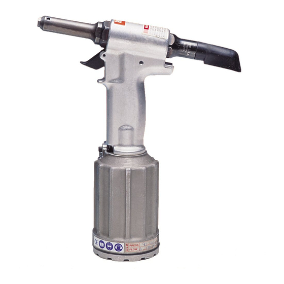
Weight of 2015B & 2015V: 5.2 lbs • Speed/Cycles: 30 per minute • Min. Capacity: 2670 lbs @ 90 psi • Air Consumption: 4.3 CFM Fasteners installed: Consult your Huck representative or available FASTENER SELECTION CHARTS. Hydraulic Fluid: Automatic Transmission Fluid, DEXRON Ill, or equivalent. - Page 6 2015 Series Tooling Alcoa Fastening Systems Fig. 1 2015 and 2015B Outline Dimensions...
- Page 7 2015 Series Tooling Alcoa Fastening Systems Fig. 1A 2015V Outline Dimensions...
-
Page 8: Principle Of Operation
2015 Series Tooling Alcoa Fastening Systems RINCIPLE OF PERATION When tool is connected to proper air supply, When fastener installation is completed, and air pressure holds throttle valve in the up position. upon trigger release, air pressure causes throttle Air pressure is directed to the top of piston keep- valve to return to its up position. -
Page 9: Reparation For Use
Connector has 1/4-18 female pipe Select correct nose assembly from the available threads to accept the hose fitting. Quick connect fit- SELECTION CHARTS or speak with your Huck tings and 1/4 inch inside diameter air hose are rec- representative. -
Page 10: Maintenance
Apply LOCKTITE* #271 Adhesive/sealant to Locknut, 505420. (LOCKTITE is available from Huck, in a tube, as A clean, well-lighted area should be available for servic- 503657.) Torque to 25-30 ft. lbs. -
Page 11: Disassembly
2015 Series Tooling Alcoa Fastening Systems ISASSEMBLY 11. Remove Retaining Ring from gland. Pull out Spacer WARNING: and Polyseal. Air hose must be disconnected before: • Removing or attaching nose assembly. • Cleaning tool and/or nose assembly. 12. Lift cylinder from handle/head. •... - Page 12 2015 Series Tooling Alcoa Fastening Systems ISASSEMBLY (continued) Figure 3 Special Disassembly Instructions for 2015B and 2015V 1. Remove Vacuum Tube from Cylinder. (2015V only) 2. Place handle/head securely in vise.Use 0100 TRUARC pliers, 502857, to remove retaining ring. Reach through window of pintail bottle.
-
Page 13: Assembly
2015 Series Tooling Alcoa Fastening Systems SSEMBLY See MAINTENANCE: GOOD SERVICE PRACTICE. dle and drive Pin through holes in handle and trig- Clean all components with mineral spirits, and inspect ger. for wear or damage. Replace as necessary. 12. Hold handle/head in vise with lower end pointing up. CAUTION: Always replace all seals, wipers and Turn cylinder bottom up, and position on handle by back-up rings on/in disassembled components. -
Page 14: Filling And Bleeding Procedure
2015 Series Tooling Alcoa Fastening Systems ILLING AND LEEDING ROCEDURE Equipment Required: Fig. 4.1 • Shop airline with 90 - 100 psi max. • Air regulator • Fill bottle, 120337, (supplied with tool). • Large flat blade screwdriver • Nose assembly or optional stall nut •... - Page 15 2015 Series Tooling Alcoa Fastening Systems ROCEDURE (continued) ILLING AND LEEDING Increase air pressure to specification. Install two 7. Stand tool upright on bench. While actuating the fasteners to check function and installation in a sin- trigger slowly (20-30 cycles), bend fill bottle at right gle stroke, or cycle tool with stall-nut fully threaded angles to tool.
-
Page 16: How To Measure Stroke
2015 Series Tooling Alcoa Fastening Systems OW TO EASURE TROKE To measure stroke of tool with stall-nut threaded onto piston: 1. Disconnect tool from airline and remove Fig. 4.3 nose from tool. 2. Reconnect tool to airline. Cycle tool and hold trigger depressed. -
Page 17: Assembly Drawings
2015 Series Tooling Alcoa Fastening Systems Figure 5 Note: Piston 125796 is not sold separately. 123757 It may be purchased as: Piston 122432 506653 Front Retaining Ring Gland Cap Assembly 125156, which includes the Gland Piston along with Polyseal 506160, 506654 Retaining Ring 506653, and Washer 506654. - Page 18 2015 Series Tooling Alcoa Fastening Systems Figure 6 Note: Piston 125796-1 is not sold separately. It may be purchased as: Piston Assembly 125156-1, which includes the Piston along with Polyseal 506160, Retaining Ring 506653, and Washer 506654. For other available assemblies, see Subassembly Part Numbers and Notes section of this manual.
-
Page 19: Sub - Assembly Parts
2015 Series Tooling Alcoa Fastening Systems Figure 7 For available assemblies, 506576 Plug & see Subassembly Part Numbers Gasket Assembly and Notes below. 100309 Bleed Plug 125116 Guard 505438 O-ring Swivel Bolt Subassembly Fill Plug and O-ring Subassembly UBASSEMBLY UMBERS AND OTES Some parts are available separately as well as in subassemblies. - Page 20 2015 Series Tooling Alcoa Fastening Systems Figure 8 500784 506565 O-ring Retaining Ring 501090 123906 Spacer 125118 Back-up Pivot Ring 506566 Polyseal Screw 501414 500786 O-ring QUAD-Ring 125139 Gland Housing 116134-1 Gland Assembly 111803-1 Piston Rod 123753-1 Air Piston 506493 Washer 111959-2 Cylinder Head 505420...
- Page 21 2015 Series Tooling Alcoa Fastening Systems Figure 10 Removing Piston and Front Gland...
- Page 22 2015 Series Tooling Alcoa Fastening Systems Figure 11 Installing Piston and Front Gland...
-
Page 23: Accessories
2015 Series Tooling Alcoa Fastening Systems CCESSORIES Pintail Collection Bag: Accessories for 2015VP: >Tailor made to fit the tool 125693 -06 Insert >Made from tough, lightweight material. 125694 Anvil Holder >Fits over the Pintail Deflector. >Velcro closure for secure fit /easy removal. Also availavle are various anvil insert kits as shown 125652 Pintail Collection Bag in Figure 13 below. -
Page 24: Roubleshooting
2015 Series Tooling Alcoa Fastening Systems ROUBLESHOOTING Always check out the simplest possible cause of a malfunction first. For example, an air hose not connected. Then proceed logically, eliminating each possible cause until the defective part is located. Where possible, sub- stitute known good parts for suspected bad parts. - Page 25 Huck or its sup- THERE ARE NO WARRANTIES WHICH EXTEND pliers.
- Page 26 The Future of Assembly Technology, The Future of Tooling to create any warranty, express, implied, or statutory; all warranties Technology, and Tools of Productivity are service marks of Huck are contained only in Huck’s written quotations, acknowledge- International. Huck provides technical assistance regarding the use ments, and/or purchase orders.
Need help?
Do you have a question about the 201 Series and is the answer not in the manual?
Questions and answers