Table of Contents
Advertisement
Quick Links
Harbor Breeze® is a registered trademark of LF,
LLC. All Rights Reserved.
ATTACH YOUR RECEIPT HERE
Serial Number
Questions, problems, missing parts? Before returning to your retailer, call our customer
service department at 1-800-643-0067, 8 a.m. - 6 p.m., EST, Monday - Thursday,
8 a.m. - 5 p.m., EST, Friday.
EB15423
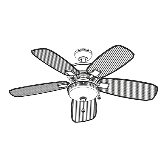
OYSTER COVE CEILING FAN
Purchase Date
1
ITEM #0451819
MODEL #00852
UL MODEL #OSC52
Español p. 23
Lowes.com/harborbreeze
Advertisement
Table of Contents

Subscribe to Our Youtube Channel
Related Manuals for LF Harbor Breeze OYSTER COVE


Summary of Contents for LF Harbor Breeze OYSTER COVE
- Page 1 ITEM #0451819 OYSTER COVE CEILING FAN MODEL #00852 UL MODEL #OSC52 Harbor Breeze® is a registered trademark of LF, Español p. 23 LLC. All Rights Reserved. ATTACH YOUR RECEIPT HERE Serial Number Purchase Date Questions, problems, missing parts? Before returning to your retailer, call our customer service department at 1-800-643-0067, 8 a.m.
-
Page 2: Table Of Contents
TABLE OF CONTENTS SAFETY INFORMATION READ AND SAVE THESE INSTRUCTIONS Safety Information....................... 3 Please read and understand this entire manual before attempting to assemble, operate, or install the product. Package Contents....................... 4 • When using an existing outlet box, be sure the box is securely attached to the building structure and can support the full weight of the fan, so as to avoid potential serious injury or death. -
Page 3: Package Contents
HARDWARE CONTENTS (shown actual size) PACKAGE CONTENTS Wire Connector Qty. 4 Fan Pull Chain Light Pull Chain Extension Extension Qty. 1 Qty. 1 (NOT TO SCALE) (NOT TO SCALE) Rubber Gasket Blade Screw PART DESCRIPTION QUANTITY Qty. 1 Qty. 16 (NOT TO SCALE) Mounting Bracket (preassembled to Canopy (B)) Canopy... -
Page 4: Initial Installation
INITIAL INSTALLATION INITIAL INSTALLATION 4. Install mounting bracket (A) to the outlet box (not 1. Determine mounting method. Outlet box included) by sliding mounting bracket (A) over two outlet A-Downrod Mount (standard or angled ceiling) box screws (not included). Securely tighten two outlet B-Closemount (standard ceiling only) box screws. -
Page 5: Closemount-Style Mounting
DOWNROD-STYLE MOUNTING CLOSEMOUNT-STYLE MOUNTING 3. Loosen preassembled set screws from the yoke on 1. Remove canopy cover (C) from bottom of canopy (B). motor housing assembly (H). Slip downrod (E) into yoke, aligning holes on both parts. Insert previously removed pin through holes on yoke and downrod (E), then insert previously removed clip into the pin until it snaps into place. -
Page 6: Wiring
CLOSEMOUNT-STYLE MOUNTING WIRING 4. Align mounting holes on canopy (B) with holes on 2. Twist wire ends together and screw wire connectors (AA) motor housing assembly (H) and fasten using three on in a clockwise direction. Tape wire connectors (AA) previously removed screws. - Page 7 FINAL INSTALLATION FINAL INSTALLATION 2. Remove fan from mounting bracket (A) hook. Align 5. Attach blade bracket (F) to motor housing assembly (H) locking slots of canopy (B) with two screws on with two blade bracket screws with washers. Securely Screws mounting bracket (A).
- Page 8 FINAL INSTALLATION FINAL INSTALLATION 8. Remove and save preassembled screws from switch 11. Add fan pull chain extension (BB) to corresponding housing (K). chain. If using fan WITHOUT light kit, continue to Step 9. Assembly is now complete. If using fan WITH light kit, proceed to Step 12. Hardware Used Screw Fan Pull Chain Extension...
- Page 9 FINAL INSTALLATION FINAL INSTALLATION 14. Insert the BLACK and WHITE wires from light kit 17. Attach switch housing (K) to switch housing cover (I). Hex nut assembly (J) through center hole in switch Align switch housing (K) holes with switch housing housing (K).
- Page 10 FINAL INSTALLATION FINAL INSTALLATION 20. Pass fan pull chain through chain guard on 23. Align holes in light frame (L) with holes on outer edge light kit assembly (J). of light kit assembly (J) and install three light frame screws (R) and securely tighten. Chain guard 21.
-
Page 11: Operating Instructions
OPERATION INSTRUCTIONS TROUBLESHOOTING 1. PULL CHAIN: PROBLEM POSSIBLE CAUSE CORRECTIVE ACTION • The fan pull chain is for motor speed control: High, Medium, Low and Off. Pull the chain once for Fan blades do not 1. Chain switch is “off”. 1. -
Page 12: Warranty
For replacement parts, call our customer service department at 1-800-643-0067, 8 a.m. - 6 p.m., EST, Monday - Thursday, 8 a.m. - 5 p.m., EST, Friday. PART DESCRIPTION PART# Blade bracket 104000-0315RW Blade 108003-304274 Glass 991300-0543FI Printed in China Harbor Breeze is a registered ® trademark of LF, LLC. All rights reserved. Lowes.com/harborbreeze Lowes.com/harborbreeze...
Need help?
Do you have a question about the Harbor Breeze OYSTER COVE and is the answer not in the manual?
Questions and answers
Where to call for replacement part for harbor breeze ceiling fan! Called Lowe’s they no longer have there replacement parts! Model #00852
Replacement parts for the LF Oyster Cove ceiling fan model #00852 can be obtained by calling the customer service department at 1-800-643-0067, Monday–Thursday from 8 a.m. to 6 p.m. EST, and Friday from 8 a.m. to 5 p.m. EST.
This answer is automatically generated