Table of Contents
Advertisement
Quick Links
HARBOR BREEZE and logo design are
trademarks or registered trademarks of
LF, LLC. All rights reserved.
ATTACH YOUR RECEIPT HERE
Serial Number
Questions, problems, missing parts? Before returning to your retailer, call our customer
service department at 888-251-1003, 8 a. m. -- 8 p.m., EST, Monday -- Sunday. You could
also contact us at partsplus@lowes.com
SS23240
Purchase Date
1
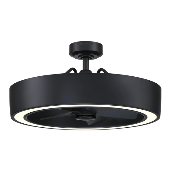
VANDERBROOK FAN
ITEM # 5249293
MODEL # HTE22027
Español p. 19
Advertisement
Table of Contents

Related Manuals for LF HARBOR BREEZE VANDERBROOK HTE22027


Summary of Contents for LF HARBOR BREEZE VANDERBROOK HTE22027
- Page 1 MODEL # HTE22027 Español p. 19 HARBOR BREEZE and logo design are trademarks or registered trademarks of LF, LLC. All rights reserved. ATTACH YOUR RECEIPT HERE Purchase Date Serial Number Questions, problems, missing parts? Before returning to your retailer, call our customer service department at 888-251-1003, 8 a.
-
Page 2: Table Of Contents
TABLE OF CONTENTS Package Contents....................... Hardware Contents......................Safety Information....................... Preparation ......................... Initial Installation Instructions ....................Standard/Angle-Mounting Instructions................. Wiring Instructions ......................Final Installation Instructions ....................Operating Instructions ......................Care and Maintenance ....................... Troubleshooting........................Limited Lifetime Warranty....................FCC Warning........................17 Replacement Part List ...................... -
Page 3: Package Contents
PACKAGE CONTENTS PART DESCRIPTION QUANTITY PART DESCRIPTION QUANTITY Clevis Pin (Preassembled on Downrod Assembly (B)) Hairpin Clip (Preassembled on Downrod Assembly (B)) Canopy Coupling (preassembled on Motor Assembly (G)) Canopy Cover Coupling Screw (preassembled on Coupling (L)) Mounting Bracket Screw (preassembled on Mounting Bracket (A)) Blade Motor Assembly... -
Page 4: Hardware Contents
HARDWARE CONTENTS (not shown actual size) Blade Screw Qty.15+1 extra SAFETY INFORMATION READ AND SAVE THESE INSTRUCTIONS Please read and understand this entire manual before attempting to assemble, operate or install the product. . All electrical connections must comply with local codes, ordinances or the National Electric Code (NEC). Contact your municipal building department to inquire about your local codes, permits and/or inspections. -
Page 5: Preparation
WARNING Chemical Burn Hazard. Keep batteries away from children. This remote contains a lithium button cell battery. If a new or used lithium button/coin cell battery is swallowed or enters the body, it can cause severe internal burns and can lead to death in as little as 2 hours. Always completely secure the battery compartment. If the battery compartment does not close securely, stop using the product, remove the batteries, and keep it away from children. -
Page 6: Initial Installation Instructions
INITIAL INSTALLATION INSTRUCTIONS Turn off circuit breakers and wall switch to the fan supply line leads. Turn Off Power Source DANGER: Failure to disconnect power supply prior to installation may result in serious injury or death. 2. Choose the desired mounting method: Standard mounting is best suited for ceilings 8 feet. -
Page 7: Standard/Angle-Mounting Instructions
INITIAL INSTALLATION INSTRUCTIONS 4. Loosen the two coupling screws (M) preassembled in coupling (L), but do not remove them. Remove the hairpin clip (K) and clevis pin (J) from the downrod assembly (B). Retain for later use. Note: Make sure to keep loose hardware separate to avoid confusion during installation. - Page 8 STANDARD/ANGLE-MOUNTING INSTRUCTIONS 3. Cut off excess fixture wires, leaving approximately 6 to 9 inches above the top of the downrod assembly (B). 6 to 9in Strip 1/2 inch of insulation from the end of each fixture wire. CAUTION: Ensure all screws are tight before moving onto the next step.
-
Page 9: Wiring Instructions
WIRING INSTRUCTIONS WARNING: To avoid possible electrical shock, be sure electricity is turned off at the main fuse box before hanging. WARNING: If you are not sure if the outlet box is grounded, contact a licensed electrician for advice, as it must be grounded for safe operation. WARNING: If house wires are different colors than referred to in the following steps, stop immediately. - Page 10 WIRING INSTRUCTIONS 2. Wrap electrical tape (not included) around each wire Outlet Box connector and make sure no bare wire or wire strands are visible after making connections. Then, turn wires upward and carefully push them into the outlet box; make sure the WHITE and GREEN connections are on GREEN one side and the BLACK connections are on the other...
-
Page 11: Final Installation Instructions
FINAL INSTALLATION INSTRUCTIONS 1. Loosen (but do not remove) the two preassembled mounting screws (N) on mounting bracket (A) that align with the slotted holes on canopy (C). Lift canopy (C) up so slotted holes engage loosened screw heads on mounting bracket (A), then twist canopy (C) clockwise, then tighten all screws securely. -
Page 12: Operating Instructions
FINAL INSTALLATION INSTRUCTIONS 4 . Attach the steel cap (H) to the motor shaft, and rotate it until it is in place. Note: Do not overtighten the steel cap (H). OPERATING INSTRUCTIONS 1. When the season changes, you may want to change the direction in which the fan spins. - Page 13 NOTE: ON DIM NOTE: Each transmitter of this remote control carries a unique ID code to facilitate communication between paired devices. The ID code is set by factory and is not user changeable. However, you will be required to perform an “ID code learning ” process manually under these circumstances: •...
-
Page 14: Care And Maintenance
OPERATING INSTRUCTIONS 5. The buttons on the remote control the fan speed and light as follows: Fan ON/OFF Brightness 25% Brightness 50% Brightness 75% Brightness 100% 9 Light Dimmer switch: a.) on “DIM”: with dimmer function. b.) on “ON” : without dimmer function NOTE: Factory set is on “DIM”... -
Page 15: Troubleshooting
TROUBLESHOOTING PROBLEM PROBABLE CAUSE CORRECTIVE ACTION 1. Set screws are loose. 1. Tighten all set screws. 2. Using non-approved speed control. 2. Some fan motors are sensitive to signals from solid- state varible speed controls. DO NOT USE a solid- state variable speed control. -
Page 16: Limited Lifetime Warranty
LIMITED LIFETIME WARRANTY The manufacturer warrants this fan to be free from defects in workmanship and material present at time of shipment from the factory for life (with limitations) from the date of purchase. This warranty applies only to the original purchaser. The manufacturer agrees to correct such defect at no charge or, at our option, replace the ceiling fan with a comparable or superior model. -
Page 17: Fcc Warning
FCC WARNING This device (including remote control and LED module) complies with Part 15 of the FCC Rules. Operation is subject to the following two conditions: (1) This device may not cause harmful interference, and (2) this device must accept any interference received, including interference that may cause undesired operation. -
Page 18: Replacement Part List
REPLACEMENT PART LIST For replacement parts, call our customer service department at 888-251-1003, 8 a.m. – 8 p.m., EST, Monday – Sunday. You could also contact us at partsplus@lowes.com. Part Description Part# Mounting Bracket A102-0084184 Downrod Assembly A103-0328019 Canopy A101-0583019 Canopy Cover A108-0013019 Coupling Cover...
Need help?
Do you have a question about the HARBOR BREEZE VANDERBROOK HTE22027 and is the answer not in the manual?
Questions and answers