Table of Contents
Advertisement
Harbor Breeze® is a registered trademark
of LF, LLC. All Rights Reserved.
Purchase Date
Questions, problems, missing parts? Before returning to your retailer, call our customer service
department at 1-800-643-0067, 8 a.m. - 8 p.m., EST, Monday - Sunday.
EB15397
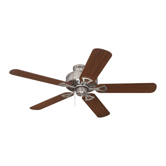
CLASSIC STYLE CEILING FAN
1
ITEM #0079837
0076888
MODEL # BDB52MBK5M
BDB52LW5M
Español p. 18
ATTACH YOUR RECEIPT HERE
LISTED
E192641
Advertisement
Table of Contents

Subscribe to Our Youtube Channel
Related Manuals for LF Harbor Breeze BDB52MBK5M


Summary of Contents for LF Harbor Breeze BDB52MBK5M
- Page 1 ITEM #0079837 0076888 CLASSIC STYLE CEILING FAN MODEL # BDB52MBK5M BDB52LW5M Harbor Breeze® is a registered trademark of LF, LLC. All Rights Reserved. Español p. 18 ATTACH YOUR RECEIPT HERE LISTED Purchase Date E192641 Questions, problems, missing parts? Before returning to your retailer, call our customer service department at 1-800-643-0067, 8 a.m.
-
Page 2: Table Of Contents
TABLE OF CONTENTS Safety Information ......................... 2 Package Contents ........................ 4 Hardware Contents ........................... 5 Preparation ........................... 5 Initial Installation ........................6 Downrod-Style Fan Mounting ....................7 Closemount-Style Fan Mounting ................... 9 Wiring ...........................11 Final Installation ........................12 Operating Instructions ......................14 Care and Maintenance ...................... - Page 3 SAFETY INFORMATION DANGER When using an existing outlet box, make sure the outlet box is securely attached to the building structure and can support the full weight of the fan. Failure to do this can result in serious injury or death.
-
Page 4: Package Contents
PACKAGE CONTENTS PART DESCRIPTION QUANTITY PART DESCRIPTION QUANTITY Downrod Motor Screw (preassembled) Canopy Lock Washer Mounting Bracket (preassembled) Motor Housing Canopy Mounting Screw Pull Chain Extension (preassembled) Blade Pin (preassembled) Blade Arm Clip (preassembled) IMPORTANT REMINDER: You must use the parts provided with this fan for proper installation and safety. -
Page 5: Hardware Contents
HARDWARE CONTENTS (shown actual size) Fiber Blade Blade Screw Wire Washer Connector Qty. 15 + 1 extra Qty. 15 Qty. 4 + 1 extra PREPARATION Before beginning assembly of product, make sure all parts are present. Compare parts with package contents list and hardware contents list. -
Page 6: Initial Installation
INITIAL INSTALLATION Turn off circuit breakers and wall switch to the fan supply line leads. DANGER: Failure to disconnect power supply prior to installation may result in serious injury or death. Determine mounting method to use. A. Downrod-style mount (standard or angled 19°... -
Page 7: Downrod-Style Fan Mounting
INITIAL INSTALLATION Secure mounting bracket (C) to outlet box (not STANDARD MOUNT ANGLE MOUNT included) using screws, spring washers and flat washers provided with the outlet box. *NOTE: It is very important you use the proper hardware when installing the mounting bracket (C) as this will support the fan. - Page 8 DOWNROD-STYLE FAN MOUNTING 2. Insert downrod (A) through canopy (B). Thread wires from motor housing (D) up through downrod (A). Slip downrod (A) into yoke, align holes and re-install pin (K) and clip (L). Tighten set screws in yoke and then tighten nuts on the set screws. Set Screw and Nut Depending on the length of downrod you use,...
-
Page 9: Closemount-Style Fan Mounting
DOWNROD-STYLE FAN MOUNTING If you decided to cut back the lead wires in Step 4, strip 1/2 in. of insulation from end of white wire. Twist stripped ends of each strand of wire within the insulation with pliers (not included). Repeat Step 5 for black, blue (if applicable) and green wires. - Page 10 CLOSEMOUNT-STYLE FAN MOUNTING Remove every other screw and lock washer from top of motor housing (D). Remove pin (K), clip (L) and preassembled set screws and nuts from yoke on motor housing (D). They are not needed for this installation type. Set Screw Yoke and Nut...
-
Page 11: Wiring
WIRING WARNING: To reduce the risk of fire, electrical shock, or personal injury, wire connectors provided with this fan are designed to accept only one 12-gauge house wire and two lead wires from the fan. If your house wire is larger than 12-gauge or there is more than one house wire to connect to the corresponding fan lead wires, consult an electrician for the proper size wire connectors to use. -
Page 12: Final Installation
WIRING IMPORTANT: Using a full range dimmer switch (not included) to control fan speed will cause a loud humming noise from fan. To reduce the risk of fire or electrical shock, do NOT use a full range dimmer switch to control fan speed. - Page 13 FINAL INSTALLATION 3. Locate motor screws (H) and lock washers (I) previously removed (Step 5, page 7). Insert two motor screws (H) along with lock washers (I) through one blade arm (G) to attach blade arm (G) to motor. Tighten motor screws (H) securely.
-
Page 14: Operating Instructions
OPERATING INSTRUCTIONS The pull chain has four positions to control fan speed. One pull is HIGH, two is MEDIUM, three is LOW and four turns the fan OFF. Use the fan reverse switch, located on the switch housing, to optimize your fan for seasonal performance. -
Page 15: Care And Maintenance
OPERATING INSTRUCTIONS 2C. IMPORTANT: Reverse switch must be set either completely UP or completely DOWN for fan to function. If the reverse switch is set in the middle position, fan will not operate. CARE AND MAINTENANCE At least twice each year, lower canopy (B) to check downrod (A) assembly, and then tighten all screws on the fan. -
Page 16: Limited Lifetime Warranty
TROUBLESHOOTING PROBLEM POSSIBLE CAUSE CORRECTIVE ACTION 1. Blades are loose. Excessive wobbling. 1. Check to be sure plastic locking mechanisms are secure. 2. Blade arms incorrectly attached. 2. Re-install blade arms. 3. Unbalanced blades. 3. Switch one blade with a blade 4. -
Page 17: Replacement Parts List
REPLACEMENT PARTS LIST For replacement parts, call our customer service department at 1-800-643-0067, 8 a.m. - 8 p.m., EST, Monday - Sunday. #0079837 #0076888 PART DESCRIPTION PART # PART # Downrod 0079837-A 0076888-A Canopy 0079837-B 0076888-B Mounting Bracket 0079837-C 0076888-C Blade 0079837-F 0076888-F...
Need help?
Do you have a question about the Harbor Breeze BDB52MBK5M and is the answer not in the manual?
Questions and answers