Advertisement
Available languages
Available languages
Quick Links
UTILITECH & logo design are trademarks or registered
trademarks of LF, LLC. All rights reserved.
Serial Number
Purchase Date
Thank you for purchasing this UTILITECH product.
Questions, problems or missing parts?
Before returning, contact us on:
866-994-4148, 8 a.m. - 8 p.m., EST, Monday - Sunday or ascs@lowes.com.
SG24774
MODEL # 7141-80-L
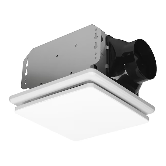
VENTILATION FAN WITH
ATTACH YOUR RECEIPT HERE
ITEM # 6270526
LED LIGHT
Español p. 13
06/2024
Advertisement

Related Manuals for LF Utilitech 7141-80-L


Summary of Contents for LF Utilitech 7141-80-L
- Page 1 ITEM # 6270526 MODEL # 7141-80-L VENTILATION FAN WITH UTILITECH & logo design are trademarks or registered LED LIGHT trademarks of LF, LLC. All rights reserved. Español p. 13 ATTACH YOUR RECEIPT HERE Serial Number Purchase Date Thank you for purchasing this UTILITECH product.
- Page 2 TABLE OF CONTENTS Product Specifications ........................2 Package Contents ..........................2 Hardware Included ..........................2 Safety Information ..........................3 Preparation ............................3 New Construction Installation ......................5 Existing Construction Installation......................7 Care and Cleaning..........................11 Troubleshooting ..........................12 Warranty ............................12 PRODUCT SPECIFICATIONS Airflow: 80 CFM LED light color (CCT): 4000K Cool White Sound output: 1.0 sone LED power consumption: 15 Watts 120 V, 60 Hz...
- Page 3 SAFETY INFORMATION Please read and understand this entire manual before attempting to assemble, operate or install the product. • Always disconnect the power supply prior to servicing the fan, WARNING: To reduce the risk of fire, electric shock, motor or junction box. or injury to persons, observe the following: •...
- Page 4 PREPARATION (Continued) Inspect duct work and wiring before proceeding with installation. Before installation, provide inspection and future maintenance access at a location that will not interfere with installation work. Installation may vary depending on how the previous ventilation fan was installed. Supplies necessary for the installation of your bath fan are not all included;...
- Page 5 NEW CONSTRUCTION INSTALLATION BEFORE INSTALLATION WARNING: RISK OF ELECTRIC SHOCK! Ensure the electricity to the wires you are working on is shut off. Either remove the fuse or turn off the circuit breaker before removing the existing bath fan or installing the new one.
- Page 6 NEW CONSTRUCTION INSTALLATION (Continued) 4. Remove the wiring box cover from the fan housing (A) with a Phillips screwdriver (not included). Remove the wiring knockout from the wiring box cover with a flathead screwdriver (not included). Wiring box cover Wiring box cover 5.
- Page 7 NEW CONSTRUCTION INSTALLATION (Continued) 8. Attach grille (B) by pinching the mounting springs and inserting them into the narrow rectangular slots in the fan housing (A). Turn on power source. Check the fan for any abnormal sounds or vibrations. Mounting springs Housing slots...
- Page 8 EXISTING CONSTRUCTION INSTALLATION INSTRUCTIONS (Continued) 3. If this fan is not replacing an old fan, be sure to cut a 7-3/4 in. x 7-1/2 in. opening for the fan housing. 4. Attach the duct connector (C) to the fan housing (A). NOTE: Remove the protective tape on the duct connector (C) flap.
- Page 9 EXISTING CONSTRUCTION INSTALLATION (Continued) 7. Pull the house wires through the hole in the wiring box cover. Quick Using the quick connectors, connect the house wiring from House wires connector the wall switch to the fan housing (A). 14 AWG is the smallest conductor that should be used for branch-circuit wiring.
- Page 10 EXISTING CONSTRUCTION INSTALLATION (Continued) 11. Plug the fan motor plug into the fan housing (A). Place the fan motor back into the fan housing (A), aligning the duct with the duct opening in the fan housing (A), and attach the fan motor to the housing using the three screws removed in step 5.
- Page 11 CARE AND CLEANING CAUTION: Before attempting to clean the fixture, disconnect the power to the fixture by turning the breaker off or removing the fuse from the fuse box. See safety information before proceeding. Routine maintenance should be done at least once a year. •...
- Page 12 CARE AND CLEANING (Continued) 5. Attach the grille (B) by pinching the mounting springs and inserting them into the narrow rectangular slots in the fan housing (A). Turn on power source. Test the unit. Mounting springs Housing slots TROUBLESHOOTING PROBLEM POSSIBLE CAUSE SOLUTION The CFM is too great.
- Page 13 ARTÍCULO # 6270526 MODELO # 7141-80-L VENTILADOR CON UTILITECH y el diseño del logotipo son marcas comerciales o marcas registradas de LF, LLC. LUZ LED Todos los derechos reservados. ADJUNTE SU RECIBO AQUÍ Número de serie Fecha de compra Gracias por comprar este producto UTILITECH.
- Page 14 TABLA DE CONTENIDO Especificaciones del producto ......................14 Contenidos del paquete........................14 Materiales incluidos ..........................14 Información de seguridad .........................15 Preparación ............................15 Instalación en construcciones nuevas ....................17 Instalación en construcciones existentes ..................19 Cuidado y limpieza ...........................23 Solución de problemas ........................24 Garantía............................24 ESPECIFICACIONES DEL PRODUCTO Flujo de aire: 2.26 m /min (80 CFM) Color de luz LED (CCT): 4000k blanco frío...
- Page 15 INFORMACIÓN DE SEGURIDAD Lea y comprenda este manual en su totalidad antes de intentar de ensamblar, operar o instalar el producto. • Siempre desconecte la fuente de alimentación antes de darle ADVERTENCIA: para reducir el riesgo de incendio, servicio al ventilador, motor o caja eléctrica. choque eléctrico o lesiones a las personas, respete lo siguiente: •...
- Page 16 PREPARACIÓN (Continuación) Inspeccione los conductos y el cableado antes de proceder con la instalación. Antes de la instalación, proporcione acceso para la inspección y el mantenimiento en un lugar que no interfiera con el trabajo de instalación. La instalacion puede variar dependiendo de cómo se instaló el ventilador anterior. Los suministros necesarios para la instalación de su ventilador de baño no están todos incluidos;...
- Page 17 INSTALACIÓN EN CONSTRUCCIONES NUEVAS PREVIO A LA INSTALACIÓN ADVERTENCIA: ¡RIESGO DE DESCARGA ELÉCTRICA! Asegúrese de cortar el suministro eléctrico en los cables con los que trabajará. Extraiga los fusibles o apague el cortacircuitos antes de quitar el ventilador de baño existente o instalar uno nuevo. 1.
- Page 18 INSTALACIÓN EN CONSTRUCCIONES NUEVAS (Continuación) 4. Retire la tapa de la caja de cableado de la carcasa del ventilador (A) con un destornillador de punta Phillips (no se incluyen). Quite el orifico ciego de cableado de la tapa de la caja de cableado con un destornillador de punta plana (no se incluyen).
- Page 19 INSTALACIÓN EN CONSTRUCCIONES NUEVAS (Continuación) 8. Fije la rejilla (B) apretando los resortes de montaje e insertándolos en las ranuras rectangulares estrechas en la carcasa del ventilador (A). Encienda la fuente de alimentación. Pruebe el ventilador en busca de sonido o vibración anormales. Resortes de montaje Ranuras...
- Page 20 INSTALACIÓN EN CONSTRUCCIONES EXISTENTES (Continuación) 3. Si este ventilador no reemplaza a uno viejo, asegúrese de cortar una abertura de 19.68 cm x 19.05 cm para la carcasa del ventilador. 4. Acople el conector del conducto (C) a la carcasa del ventilador (A).
- Page 21 INSTALACIÓN EN CONSTRUCCIONES EXISTENTES (Continuación) 5. Jale los cables de la casa a través de la tapa la cubierta de la caja de cableado. Cables de la casa Conector rápido Usando los conectores rápidos, conecte el cableado de la carcasa desde el interruptor de pared a la carcasa del ventilador (A).
- Page 22 INSTALACIÓN EN CONSTRUCCIONES EXISTENTES (Continuación) 11. Vuelva a enchufar el enchufe del motor del ventilador a la carcasa del ventilador (A). Vuelva a colocar el motor del ventilador en la carcasa del ventilador (A), alineando el conducto con la abertura del conducto en la carcasa del ventilador (A), y fíjelos con los tornillos que retiró...
- Page 23 CUIDADO Y LIMPIEZA PRECAUCIÓN: antes de limpiar el aparato, desconecte el suministro eléctrico hacia este apagando el cortacircuitos o extrayendo el fusible de la carcasa de fusibles. Consulte la información sobre seguridad antes de proceder. Se debe hacer mantenimiento de rutina al menos una vez al año. •...
- Page 24 CUIDADO Y LIMPIEZA (Continuación) 5. Coloque la rejilla (B) pellizcando los resortes de montaje y se insertan en las ranuras rectangulares estrechas en la carcasa del ventilador (A). Encienda la fuente de alimentación. Pruebe la unidad. Resortes de montaje Ranuras en la carcasa SOLUCIÓN DE PROBLEMAS...
Need help?
Do you have a question about the Utilitech 7141-80-L and is the answer not in the manual?
Questions and answers