Table of Contents
Advertisement
HARBOR BREEZE and logo design are trademarks or
registered trademarks of LF, LLC. All rights reserved.
ATTACH YOUR RECEIPT HERE
Purchase Date _________________________
Thank you for purchasing this HARBOR BREEZE product.
Questions, problems, or missing parts?
Before returning, contact us at:
888-251-1003, 8 a.m. - 8 p.m., EST, Monday - Sunday or at ascs@lowes.com.
SS24037
ITEM #5497045, 5497046, 5497047,5497048
MODEL #43349, 43350, 43367, 43368
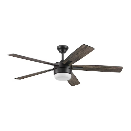
BOLTZ III CEILING FAN
1
Español p. 19
Advertisement
Table of Contents

Related Manuals for LF Harbor Breeze BOLTZ III 43349


Summary of Contents for LF Harbor Breeze BOLTZ III 43349
- Page 1 MODEL #43349, 43350, 43367, 43368 BOLTZ III CEILING FAN Español p. 19 HARBOR BREEZE and logo design are trademarks or registered trademarks of LF, LLC. All rights reserved. ATTACH YOUR RECEIPT HERE Purchase Date _________________________ Thank you for purchasing this HARBOR BREEZE product.
-
Page 2: Table Of Contents
TABLE OF CONTENTS Package Contents ..............3 Hardware Contents . -
Page 3: Package Contents
PACKAGE CONTENTS PART DESCRIPTION QUANTITY Downrod Downrod Pin (preassembled to Downrod [A]) Downrod Clip (preassembled to Downrod [A]) Mounting Bracket (preassembled to Canopy [E]) Canopy Canopy Cover (preassembled to Canopy [E]) Mounting Bracket Screw (preassembled to Mounting Bracket [D]) Yoke Cover Motor Assembly Set Screw (preassembled to Motor Assembly [I]) Fitter Plate (preassembled to Motor Assembly [I]) -
Page 4: Hardware Contents
HARDWARE CONTENTS (shown actual size) Wire Connector Lead Wire Push-in Qty. 1 Qty. 1 Connector + 1 extra Qty. 2 + 1 extra... -
Page 5: Safety Information
SAFETY INFORMATION Please read and understand this entire manual before attempting to assemble, operate or install the product. • Before you begin installing the fan, disconnect the power by removing fuses or turning off the circuit breakers. • Make sure all electrical connections comply with local codes, ordinances, the National Electrical Code and ANSI/NFPA 70-199. -
Page 6: Preparation
SAFETY INFORMATION CAUTION: Read all instructions and safety information before installing your new fan. Review the accompanying assembly diagrams. CAUTION: Be sure the outlet box is properly grounded or that a ground (green or bare) wire is present. CAUTION: Carefully check all screws, bolts and nuts on the fan motor assembly to ensure they are secured. -
Page 7: Initial Installation
INITIAL INSTALLATION 1. Turn off the circuit breakers and the wall switch to the fan supply line leads. DANGER: Failure to disconnect the power supply prior to installation may result in serious injury or death. 2. Determine the mounting method to use. Standard Mounting is best suited for ceilings 8 ft. - Page 8 INITIAL INSTALLATION 4. Loosen all four preassembled mounting bracket screws (G), then completely remove the two mounting bracket screws (G) from the round holes of canopy (E). Set aside for later use. Turn the canopy in a counterclockwise direction. Detach mounting bracket (D) from canopy (E).
- Page 9 INITIAL INSTALLATION 7. Insert the downrod (A) -- or a longer downrod (not included), if required -- through the canopy (E) and yoke cover (H). Feed the wires from the fan through the downrod (A). Depending on the length of downrod (A) you use, you may need to use the 36-inch lead wire (M) to accomodate a 36 or 48-inch downrod (sold separately).
-
Page 10: Wiring
WIRING WARNING: To reduce the risk of fire, electrical shock or personal injury, wire connectors provided with this fan are designed to accept only one 12-gauge house wire and two lead wires from the fan. If your house wire is larger than 12-gauge and there is more than one house wire to connect to the two fan lead wires, consult an electrician for the proper size wire connectors to use. -
Page 11: Final Installation
FINAL INSTALLATION 1. Align the canopy (E) over the loosened mounting bracket screws (G) preassembled on mounting bracket (D). Place the keyhole slot of the canopy (E) onto the mounting bracket screws (G) and rotate the canopy (E) clockwise. Secure the canopy (E) with the mounting bracket screws (G) previously removed (Step 4, page 8). - Page 12 FINAL INSTALLATION Remote contro from remote pack (S) comes equipped with a wall bracket. If you wish to install the wall bracket, remove the small plate to expose the screw holes. Insert wall brackets screws through holes and into wall, then cover with the previously removed small plate.
-
Page 13: Operating Instructions
OPERATING INSTRUCTIONS 1. To operate the fan using remote control, press and release the following buttons: Indicator LED Indicator - Indicates the three speeds of the fan. It should illuminate when any remote button is pressed. If Fan Power not, replace the 1.5V, AAA batteries. Fan Power button has three options: Sleep Timer ) - Turns the fan off or turns on fan at previously... - Page 14 OPERATING INSTRUCTIONS 3. Using a ceiling fan will allow you to raise your thermostat setting in summer and lower your thermostat setting in winter without feeling a difference in your Reverse comfort. Switch In warmer weather, push the reverse switch left to display a sun icon, which will result in downward airflow creating a wind chill effect (Fig.
-
Page 15: Care And Maintenance
CARE AND MAINTENANCE At least twice each year, lower the canopy to check the downrod assembly, and then tighten all screws on the fan. Clean the motor housing with only a soft brush or lint-free cloth to avoid scratching the finish. Clean the blades with a lint-free cloth. Total fixture wattage is 23 watts;... - Page 16 TROUBLESHOOTING PROBLEM POSSIBLE CAUSE CORRECTIVE ACTION The fan operates 1. The light kit wire plugs are not 1. Ensure the 6-pin connectors in the light correctly, but the connected properly. kit are connected properly. lights are not 2. Turn the power off and check all working.
-
Page 17: Limited Lifetime Warranty
LIMITED LIFETIME WARRANTY Set forth below, the manufacturer warrants the fan motor for this ceiling fan to be free from defects in workmanship and material for the life of the product. Also, subject to the limitations below, the manufacturer warrants all ceiling fan parts (“ceiling fan parts” excludes the motor and parts made in whole or in part with glass) to be free from defects in workmanship and material for a period of one year after the date of purchase by the original purchaser at retail. -
Page 18: Replacement Parts List
REPLACEMENT PARTS LIST For replacement parts, call the customer service department at 888-251-1003, 8 a.m. - 8 p.m., EST, Monday - Sunday. You could also contact us at ascs@lowes.com. PART DESCRIPTION #5497045 #5497046 #5497047 #5497048 Downrod 4L000013820 4L000007500 4L000017430 4L000015030 Mounting Bracket 4L000006350 4L000006410 4L000006350 4L000011050 Canopy...
Need help?
Do you have a question about the Harbor Breeze BOLTZ III 43349 and is the answer not in the manual?
Questions and answers
Why is my newly installed fan doing whatever it wants. Light goes dim. Fan changes speed or shuts off.