Table of Contents
Advertisement
HARBOR BREEZE® and logo design are trademarks
or registered trademarks of LF, LLC. All rights reserved.
ATTACH YOUR RECEIPT HERE
Serial Number
Questions, problems, missing parts? Before returning to your retailer, call our customer
service department at
contact us at partsplus@lowes.com.
SC22340
Purchase Date
888-251-1003, 8 a.m. - 8 p.m., EST, Monday - Sunday. You could also
1
ITEM #5613098
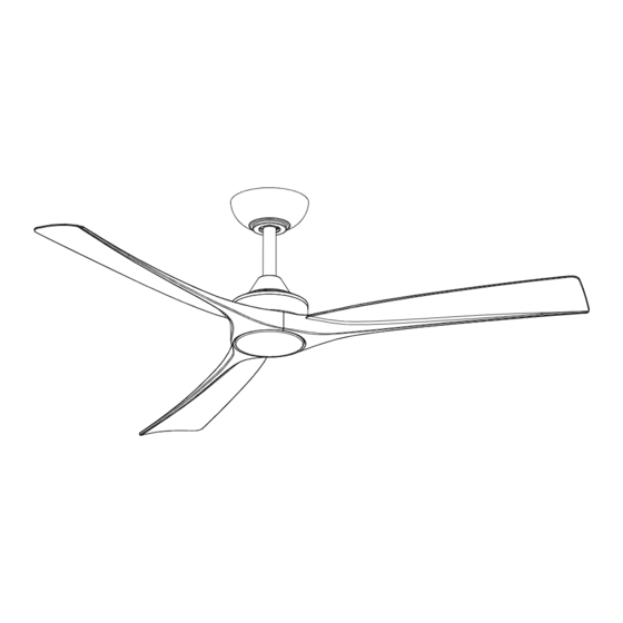
52" CALAVAR
CEILING FAN
MODEL #84401
Español p. 19
ATTACH YOUR RECEIPT HERE
Advertisement
Table of Contents

Related Manuals for LF Harbor Breeze CALAVAR 52


Summary of Contents for LF Harbor Breeze CALAVAR 52
- Page 1 52" CALAVAR CEILING FAN MODEL #84401 Español p. 19 HARBOR BREEZE® and logo design are trademarks or registered trademarks of LF, LLC. All rights reserved. ATTACH YOUR RECEIPT HERE ATTACH YOUR RECEIPT HERE Serial Number Purchase Date Questions, problems, missing parts? Before returning to your retailer, call our customer service department at 888-251-1003, 8 a.m.
-
Page 2: Table Of Contents
TABLE OF CONTENTS Safety Information ........................2 Package Contents ........................4 Hardware Contents ........................... 5 Preparation ........................... 5 Initial Installation ........................Assembly-Hanging The Fan ....................Assembly-Making The Electrical Connection ............... 8 Installing The Blades And Light Kit ..................Operating Instructions ...................... - Page 3 SAFETY INFORMATION WARNING WARNING To reduce the risk of fire, electrical shock or personal injury, mount fan to outlet box marked "ACCEPTABLE FOR FAN SUPPORT OF 35 LBS. OR LESS" and use mounting screws provided with the outlet box. Most outlet boxes commonly used for the support of lighting fixtures are not acceptable for fan support and may need to be replaced.
-
Page 4: Package Contents
PACKAGE CONTENTS PART DESCRIPTION PART DESCRIPTION QUANTITY QUANTITY Hanger Ball (preassembled) Blade Downrod (preassembled) 18 W LED Assembly Mounting Bracket Receiver Canopy Transmitter Canopy Cover Transmitter Holder Coupling Cover 12V Battery Fan Motor Assembly Extension power cord (18+24+24 inch) Light plate IMPORTANT REMINDER: You must use the parts provided with this fan for proper installation and safety. -
Page 5: Hardware Contents
HARDWARE CONTENTS (shown actual size) Balancing Blade Screw Remote Control Wire Nuts (Preassembled) Holder Mounting Qty. 3 Qty. 1 Screws Qty. 6 Qty. 2 + 1 extra PREPARATION Before beginning assembly of product, make sure all parts are present. Place motor on carpet or on foam to avoid damage to finish. - Page 6 INITIAL INSTALLATION 2. Determine mounting method to use. IMPORTANT: If using the angle mount, check to make sure the ceiling angle is not steeper than 18°. *Helpful Hint: Downrod-style mounting is best 18° max. suited for ceilings 8 ft. or higher. For taller ceilings you may want to use a longer downrod (not included).
-
Page 7: Assembly-Hanging The Fan
ASSEMBLY-HANGING THE FAN 1. Remove the hanger ball (A) from the downrod (B) Cross Pin by loosening the hanger ball set screw and removing the cross pin, then sliding the hanger Hanger Ball ball (A) off of the downrod (B). Set Screw Loosen the two set screws from the fan motor assembly coupling, Remove the hitch pin... -
Page 8: Assembly-Making The Electrical Connection
ASSEMBLY-MAKING THE ELECTRICAL CONNECTION WARNING: To reduce the risk of fire, electrical shock or personal injury, wire connectors provided with this fan are designed to accept only one 12-gauge house wire and two lead wires from the fan. If your house wire is larger than 12-gauge or there is more than one house wire to connect to the corresponding fan lead wires, consult an electrician for the proper size wire connectors to use. - Page 9 ASSEMBLY-MAKING THE ELECTRICAL CONNECTION (CONTINUED) 3. Making the electrical connections WARNING: To avoid possible electrical shock, ensure the electricity is turned off at the circuit breaker or main fuse box before wiring. WARNING: Check to see that all connections are tight, including the ground, and that no Outlet Box bare wire is visible at the wire nuts, except for the ground wire.
- Page 10 ASSEMBLY-MAKING THE ELECTRICAL CONNECTION (CONTINUED) Wrap electrical tape (not included) around each individual wire connector (CC) down to the wire. WARNING: Make sure no bare wire or wire strands are visible after making connections. Place GREEN and WHITE connections on opposite side of the outlet box from the BLACK and BLUE (if applicable) connections.
-
Page 11: Installing The Blades And Light Kit
INSTALLING THE BLADES AND LIGHT KIT Loosen the screws on the fan motor Remove the six blade screws (AA) from the fan motor assembly (G) . Keep the screws for subsequent steps. 2. Install the fan blades Pay attention to the arrow on the bottom of the fan motor assembly (G) . - Page 12 INSTALLING THE BLADES AND LIGHT KIT(CONTINUED) 4. Connect the wire While holding the 18W LED assembly (J) under your fan, firmly snap the wire connection plugs together. 5. Twist the 18W LED assembly tightly Attach the 18W LED assembly (J) to the light plate (H) by twisting tightly.
-
Page 13: Operating Instructions
OPERATING INSTRUCTIONS CAUTION: The remote control transmitter can be programmed to multiple receivers or fans. If this is not desired, turn wall switch off to any other programmable receiver or fan. FCC Compliance Statement: products subject to Part 15 CAUTION: Changes or modifications not expressly approved by the party responsible for compliance could void the user's authority to operate the equipment. - Page 14 OPERATING INSTRUCTIONS(CONTINUED) 2. Remote control operating instructions Remote Control only: Install an A23 12 volt battery (included). To prevent damage to transmitter remove the battery if not used for long periods of time. Your DC brushless motor is equipped with a self learning frequency function remote control.
- Page 15 OPERATING INSTRUCTIONS(CONTINUED) The learning frequency function and self calibration test will continue to retain the last set frequency and calibration set even when the AC power is shut off. If the frequency is changed, the self calibration test will occur again. 3a.
-
Page 16: Care And Maintenance
OPERATING INSTRUCTIONS(CONTINUED) 5. Attach the remote control holder to the wall with the two remote control holder (M) mounting screws (BB). Wall CARE AND MAINTENANCE DO NOT Do not use water when cleaning, Water could Check the support connections, brackets, and damage the motor, or the wood, or possibly blade attachments twice a year. -
Page 17: Troubleshooting
TROUBLESHOOTING WARNING: Ensure the power is off at the electrical panel box before you attempt any repairs. Refer to the section "Making the Electrical Connections" on page 9. PROBLEM SOLUTION Check main and branch circuit fuses or breakers. Check line wire connections to the fan and switch wire connections in the switch The fan will not housing. -
Page 18: Limited Lifetime Warranty
LIMITED LIFETIME WARRANTY The distributor warrants this fan to be free from defects in workmanship and materials present at time of shipment from the factory for Lifetime limited from the date of purchase. This warranty applies only to the original purchaser. The distributor agrees to correct any defect at no charge or, at our option, replace the ceiling fan with a comparable or superior model.
Need help?
Do you have a question about the Harbor Breeze CALAVAR 52 and is the answer not in the manual?
Questions and answers
i have missing parts how do i get them i'm missing light plate18 w led assembly canoply
To obtain missing parts for the Harbor Breeze CALAVAR 52, including the light plate, 18W LED assembly, and canopy, contact the customer service department at 888-251-1003 between 8 a.m. and 8 p.m. EST, Monday through Sunday. You can also email partsplus@lowes.com.
This answer is automatically generated