Table of Contents
Advertisement
HARBOR BREEZE and logo design are
trademarks or registered trademarks of
LF, LLC. All rights reserved.
Purchase Date
Questions, problems, missing parts? Before returning to your retailer, call our customer
service department at
also contact us at ascs@lowes.com.
SS23573
888-251-1003, 8 a.m. - 8 p.m., EST, Monday - Sunday. You could
1
ITEM #5497055
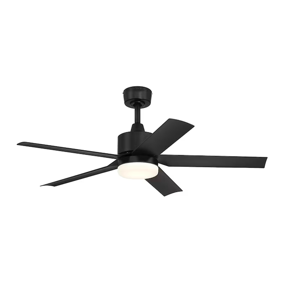
REIDSPORT LED
MODEL #RDS44MBK5LR
RDS44BNK5LR
Español p. 22
ATTACH YOUR RECEIPT HERE
ADJUNTE SU RECIBO AQUÍ
4009218
APPROVED FOR USE
IN DAMP LOCATIONS
5497056
Advertisement
Table of Contents

Subscribe to Our Youtube Channel
Related Manuals for LF HARBOR BREEZE REIDSPORT LED RDS44MBK5LR


Summary of Contents for LF HARBOR BREEZE REIDSPORT LED RDS44MBK5LR
- Page 1 REIDSPORT LED MODEL #RDS44MBK5LR RDS44BNK5LR HARBOR BREEZE and logo design are trademarks or registered trademarks of Español p. 22 LF, LLC. All rights reserved. ATTACH YOUR RECEIPT HERE ADJUNTE SU RECIBO AQUÍ 4009218 APPROVED FOR USE Purchase Date IN DAMP LOCATIONS...
-
Page 2: Table Of Contents
TABLE OF CONTENTS Safety Information .........................2 Package Contents ........................5 Hardware Contents .......................6 Preparation ..........................6 Initial Installation ........................6 Downrod-Style Fan Mounting ....................8 Closemount-Style Fan Mounting ..................10 Wiring ..........................11 Final Installation ........................14 Operating Instructions ......................17 Care and Maintenance .......................19 Troubleshooting ........................20 Limited Lifetime Warranty ....................21 Replacement Parts List ......................21 SAFETY INFORMATION CAUTION: Changes or modifications not approved by the party responsible for compliance could void... - Page 3 SAFETY INFORMATION READ AND SAVE THESE INSTRUCTIONS • Do not discard fan carton or foam inserts. Should this fan need to be returned to the factory for repairs, it must be shipped in its original packaging to ensure proper protection against damage that might exceed the initial cause for return.
- Page 4 SAFETY INFORMATION WARNING To reduce the risk of fire, electrical shock or personal injury, do not bend the blades when installing them, balancing the blades or cleaning the fan. Do not insert objects between the rotating fan blades. To reduce the risk of personal injury, use ONLY parts provided with this fan. The use of parts OTHER than those provided with this fan will void the warranty.
-
Page 5: Package Contents
PACKAGE CONTENTS PART DESCRIPTION PART DESCRIPTION QUANTITY QUANTITY Motor Plate Screw Downrod (preassembled) Mounting Bracket Fitter Plate Screw (preassembled) (preassembled) Canopy Canopy Mounting Screw (preassembled) (preassembled) Yoke Cover Remote Control Receiver Motor Housing Remote Pack Shade LED Light Kit IMPORTANT REMINDER: Fitter Plate You must use the parts Blade... -
Page 6: Hardware Contents
HARDWARE CONTENTS (shown actual size) Blade Screw/ Wire Lock Washer/ Connector Flat Washer Qty. 4 Qty. 10 + 1 extra PREPARATION Before beginning assembly of product, make sure all parts are present. Place motor on carpet or on foam to avoid damage to finish. Compare parts with package contents list and hardware contents list. If any part is missing or damaged, do not attempt to assemble the product. - Page 7 INITIAL INSTALLATION 2. Determine mounting method to use. A. Downrod mount (standard or angled ceiling). 19° max. B. Closemount (standard ceiling only). IMPORTANT: If using the angle mount, check to make sure the ceiling angle is not steeper than 19°. *Helpful Hint: Downrod-style mounting is best suited for ceilings 8 ft.
-
Page 8: Downrod-Style Fan Mounting
INITIAL INSTALLATION Secure mounting bracket (B) to outlet box (not included) using screws, spring washers and flat ANGLE STANDARD MOUNT washers provided with the outlet box. MOUNT *NOTE: It is very important you use the proper hardware when installing the mounting bracket (B) as this will support the fan. - Page 9 DOWNROD-STYLE FAN MOUNTING 3. Slip downrod (A) into yoke, align holes and re-install pin (J) and clip (K). Tighten downrod set screws and then tighten nut. Set Screw and Nut Depending on the length of downrod you use, you may need to cut the lead wires back to simplify the 8 in.
-
Page 10: Closemount-Style Fan Mounting
DOWNROD-STYLE FAN MOUNTING 6. Install hanging ball of downrod (A) into opening of mounting bracket (B). Align one of the slots in hanging ball with the tab in mounting bracket (B). DANGER: Failure to align one of the slots in hanging ball with the tab in mounting bracket (B) may result in serious injury or death. -
Page 11: Wiring
CLOSEMOUNT-STYLE FAN MOUNTING 3. Pull wires up through hole in the middle of the canopy (C) and attach canopy (C) to motor Screw housing (E) using the three screws/lock Lock washers previously removed. Washer Temporarily hang fan on the tab on the mounting bracket (B) using one of the non-slotted holes in the canopy (C). - Page 12 WIRING IMPORTANT: Make the necessary wiring Wire Connectors connections for remote control operation as detailed in Step 1b below. For each wire connection, use one of the wire connectors from the remote pack (P), making sure to screw wire connector on in a clockwise direction. Connect all GROUND (GREEN) wires from fan (on GROUND (GREEN OR BARE) WHITE SUPPLY WIRE...
- Page 13 WIRING Wrap electrical tape (not included) around each individual wire connector (BB) down to the wire. WARNING: Make sure no bare wire or wire strands are visible after making connections. Place GREEN and WHITE connections on opposite side of the outlet box from the BLACK and BLUE (if applicable) connections.
-
Page 14: Final Installation
FINAL INSTALLATION Lift canopy (C) to mounting bracket (B) aligning slotted holes in canopy (C) with loosened canopy mounting screws (N) in Downrod Closemount mounting bracket (B). Twist canopy (C) Option Option clockwise to lock. Re-insert the two canopy mounting screws (N) that were previously removed (Step 4, Page 7) and tighten all canopy mounting screws (N) securely. - Page 15 FINAL INSTALLATION 3. Partially loosen two motor plate screws (L) in motor plate on underside of motor housing (E) and remove the other motor plate screw (L). Align slotted holes in fitter plate (H) with loosened motor plate screws (L), allowing molex connections from motor housing (E) to come through hole in fitter plate (H).
- Page 16 FINAL INSTALLATION 6. Carefully arrange wiring within the fitter plate (H) to ensure wires do not get pinched when attaching the LED light kit (G). Align slotted holes in LED light kit (G) with loosened fitter plate screws (M) on posts on fitter plate (H). Twist LED light kit (G) to lock.
-
Page 17: Operating Instructions
OPERATING INSTRUCTIONS CAUTION: The remote control transmitter can be programmed to multiple receivers or fans. If this is not desired, turn wall switch off to any other programmable receiver or fan. FCC Compliance Notice for Remote Control and LED Light Kit CAUTION: Changes or modifications not approved by the party responsible for compliance could void the user's authority to operate the equipment. - Page 18 OPERATING INSTRUCTIONS 2. Restore electrical power. Within 30 seconds of powering fan, press and hold LEARN button on the LEARN back of remote control transmitter for 5 seconds (or button until light turns on) in order to synchronize remote with fan motor. Use the remote control transmitter to test the light and fan functions to confirm the learning process is complete.
-
Page 19: Care And Maintenance
OPERATING INSTRUCTIONS In warmer weather, setting the reverse switch in the LEFT position will result in downward airflow creating a wind chill effect. In cooler weather, setting the reverse switch in the RIGHT position will result in upward airflow that can help move stagnant, hot air off the ceiling area. -
Page 20: Troubleshooting
TROUBLESHOOTING WARNING: Before beginning work, shut off the power supply to avoid electrical shock. PROBLEM POSSIBLE CAUSE CORRECTIVE ACTION Fan does not move. 1. Reverse switch not engaged. 1. Push switch firmly either left or right. 2. Power is off or fuse is blown. 2. -
Page 21: Limited Lifetime Warranty
LIMITED LIFETIME WARRANTY Set forth below, the manufacture warrants the fan motor for this ceiling fan to be free from defects in workmanship and material for the life of the product. Also, subject to the limitations below, the manufacturer warrants all ceiling fan parts (“ceiling fan parts” excludes the motor and parts made in whole or in part with glass) to be free from defects in workmanship and material for a period of one year after the date of purchase by the original purchaser at retail.
Need help?
Do you have a question about the HARBOR BREEZE REIDSPORT LED RDS44MBK5LR and is the answer not in the manual?
Questions and answers