Table of Contents
Advertisement
Harbor Breeze® is a registered trademark
of LF, LLC. All Rights Reserved.
ATTACH YOUR RECEIPT HERE
Purchase Date _________________________
Questions, problems, missing parts? Before returning to your retailer, call our customer
service department at 1-800-643-0067, 8 a.m. - 6 p.m., EST, Monday - Thursday,
8 a.m. - 5 p.m., EST, Friday.
BM18037
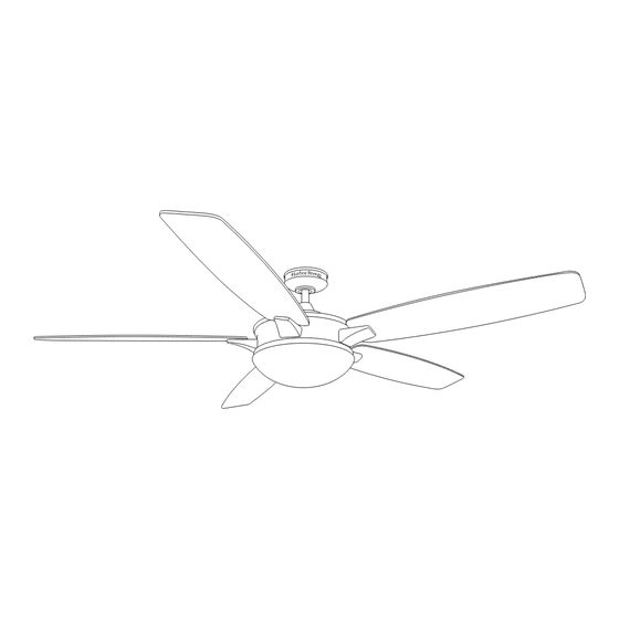
KINGSBURY CEILING FAN
1
ITEM #0184428
MODEL #40943
Spanish p. 22
Advertisement
Table of Contents

Subscribe to Our Youtube Channel
Related Manuals for LF Harbor Breeze KINGSBURY


Summary of Contents for LF Harbor Breeze KINGSBURY
- Page 1 KINGSBURY CEILING FAN MODEL #40943 Spanish p. 22 Harbor Breeze® is a registered trademark of LF, LLC. All Rights Reserved. ATTACH YOUR RECEIPT HERE Purchase Date _________________________ Questions, problems, missing parts? Before returning to your retailer, call our customer service department at 1-800-643-0067, 8 a.m. - 6 p.m., EST, Monday - Thursday, 8 a.m.
-
Page 2: Table Of Contents
TABLE OF CONTENTS Package Contents ..............3 Hardware Contents . -
Page 3: Package Contents
PACKAGE CONTENTS PART DESCRIPTION QUANTITY Downrod Downrod Pin (preassembled to Downrod [A]) Downrod Clip (preassembled to Downrod [A]) Mounting Bracket (preassembled to Canopy [E]) Canopy Canopy Cover (preassembled to Canopy [E]) Light Kit Motor Assembly Fitter Plate (preassembled to Motor Assembly [H]) Yoke Cover Blade Arm Blade... -
Page 4: Hardware Contents
HARDWARE CONTENTS (shown actual size) Wire Connector Blade Screw Blade Washer Motor Screw Qty. 3 Qty. 15 Qty. 15 Qty. 10 + 1 extra + 1 extra + 1 extra + 1 extra... -
Page 5: Safety Information
SAFETY INFORMATION Please read and understand this entire manual before attempting to assemble, operate or install the product. • Before you begin installing the fan, disconnect the power by removing fuses or turning off the circuit breakers. • Make sure that all electrical connections comply with local codes, ordinances, the National Electrical Code, and ANSI/NFPA 70-199. -
Page 6: Preparation
SAFETY INFORMATION CAUTION: Be sure the outlet box is properly grounded or that a ground (green or bare) wire is present. CAUTION: Carefully check all screws, bolts and nuts on the fan motor assembly to ensure they are secured. CAUTION: This equipment has been tested and found to comply with the limits for a Class B digital device, pursuant to Part 15 of the FCC Rules. -
Page 7: Initial Installation
INITIAL INSTALLATION 1. Turn off the circuit breakers and the wall switch to the fan supply line leads. DANGER: Failure to disconnect the power supply prior to installation may result in serious injury or death. 2. Determine the mounting method to use. Standard mounting is best suited for ceilings 8 ft. - Page 8 INITIAL INSTALLATION 4. Loosen all four preassembled mounting bracket screws (R), then completely remove the two mounting bracket screws (R) from the round holes of canopy (E). Set aside for later use. Detach mounting bracket (D) from canopy (E). 5. Attach mounting bracket (D) to outlet box (not included) using screws and washers provided with Standard or Closemount...
-
Page 9: Standard Or Angle Mounting Instructions
STANDARD OR ANGLE MOUNTING INSTRUCTIONS 1. Remove the downrod pin (B) and downrod clip (C) from the downrod (A). Then partially loosen the set screws (Q) in the yoke at the top of the motor housing (H). 2. Insert the downrod (A) through the canopy (E) and yoke cover (J). - Page 10 STANDARD OR ANGLE MOUNTING INSTRUCTIONS 4. Depending on the length of downrod you use, you may need to cut the lead wires back to simplify the wiring. If you decide to cut back the lead wires, it is suggested you do so in the following manner: 8 in.
-
Page 11: Closemount Instructions
CLOSEMOUNT INSTRUCTIONS 1. Remove the canopy cover (F) from the bottom of the canopy (E). Helpful Hint: The downrod (A), canopy cover (F), and yoke cover (J) are not used in this type of installation. 2. Remove three Phillips-head closemount screws (U) from the top of the motor assembly (H). -
Page 12: Wiring
WIRING WARNING: To reduce the risk of fire, electrical shock or personal injury, wire connectors provided with this fan are designed to accept only one 12-gauge house wire and two lead wires from the fan. If your house wire is larger than 12-gauge and/or there is more than one house wire to connect to the two fan lead wires, consult an electrician for the proper size wire connectors to use. -
Page 13: Final Installation
FINAL INSTALLATION Note: The downrod (A), canopy cover (F), and yoke cover (J) are not used in this type of installation. 1. Align the canopy (E) over the loose mounting bracket screws (R) preassembled on mounting bracket (D). Place the keyholes of the canopy (E) onto the mounting bracket screws (R) and rotate the canopy (E) clockwise. - Page 14 FINAL INSTALLATION 3. Partially insert three blade screws (BB), along with three blade washers (CC) through one blade (L) and into one blade arm (K). Tighten each blade screw (BB) with a Phillips screwdriver (not included), starting with the one in the middle. Repeat this step for the remaining blades (L) and blade arms (K).
- Page 15 FINAL INSTALLATION 6. Remove one of the three light pan screws (T) from the light pan (N) and loosen the other two screws. Connect the wire connectors (white to white and black to blue) from the motor assembly (H) to the light kit (G). Align the screw holes of the light kit (G) with the loosened light pan screws (T) and replace previously removed light pan screw (T).
- Page 16 FINAL INSTALLATION 9. Remove the battery cover from the back of the remote found in remote pack (L). Insert the battery from remote pack (L) into the remote; ensure polarity of battery matches the polarity indicated in the battery compartment -- positive (+) to positive (+) and negative (-) to negative (-).
-
Page 17: Operating Instructions
OPERATING INSTRUCTIONS 1. To operate the fan using remote control (P), press and release the following buttons: Speed Control - Controls fan speed 1 (low) - 6 (high). Fan On/Off - Turns fan off or turns fan on at most Speed recently selected speed. -
Page 18: Care And Maintenance
CARE AND MAINTENANCE At least twice each year, lower the canopy to check the downrod assembly, and then tighten all screws on the fan. Clean the motor housing with only a soft brush or lint-free cloth to avoid scratching the finish. Clean the blades with a lint-free cloth. Bulb Replacement: Use 40-watt max. - Page 19 TROUBLESHOOTING PROBLEM POSSIBLE CAUSE CORRECTIVE ACTION 1. The blades and/or blade are 1. Check and tighten all screws that hold loose. the fan blades to the blade arms and the blade arms to the motor. 2. The blades are unbalanced. 2.
-
Page 20: Limited Lifetime Warranty
LIMITED LIFETIME WARRANTY The manufacturer warrants this fan to be free from defects in workmanship and materials present at time of shipment from the factory for a lifetime from the date of purchase by the original purchaser. The retailer also warrants that all other fan parts, excluding any glass or plastic blades, to be free from defects in workmanship and material at the time of shipment from the factory for a period of one year after the date of purchase by the original purchaser. -
Page 21: Replacement Parts List
REPLACEMENT PARTS LIST For replacement parts, call the customer service department at 1-800-643-0067, 8 a.m. - 6 p.m., EST, Monday - Thursday, 8 a.m. - 5 p.m., EST, Friday. PART DESCRIPTION PART# Downrod 4L000008850 Mounting Bracket 4L000008860 Canopy 4L000004140 Canopy Cover 4L000004170 Light Kit 4L000006720...
Need help?
Do you have a question about the Harbor Breeze KINGSBURY and is the answer not in the manual?
Questions and answers