Advertisement
Table of Contents
- 1 Table of Contents
- 2 Package Contents
- 3 Hardware Contents
- 4 Safety Information
- 5 Preparation
- 6 Initial Installation Instructions
- 7 Standard/Angle-Mounting Instructions
- 8 Wiring Instructions
- 9 Final Installation Instructions
- 10 Operating Instructions
- 11 Care and Maintenance
- 12 Troubleshooting
- 13 Limited Lifetime Warranty
- 14 FCC Warning
- 15 Replacement Part List
- Download this manual
Harbor Breeze
®
is a registered trademark
of LF, LLC. All Rights Reserved.
ATTACH YOUR RECEIPT HERE
Serial Number
Questions, problems, missing parts? Before returning to your retailer, call our customer
service department at 1-800-643-0067, 8 a.m. - 6 p.m., EST, Monday - Thursday,
8 a.m. - 5 p.m., EST, Friday.
PH19239
Purchase Date
1
ITEM #0883772
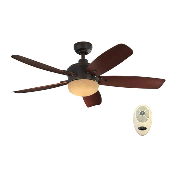
SARATOGA
CEILING FAN
MODEL #L1902
Español p. 19
Advertisement
Table of Contents

Related Manuals for LF Harbor Breeze L1902


Summary of Contents for LF Harbor Breeze L1902
- Page 1 CEILING FAN Harbor Breeze ® is a registered trademark MODEL #L1902 of LF, LLC. All Rights Reserved. Español p. 19 ATTACH YOUR RECEIPT HERE Purchase Date Serial Number Questions, problems, missing parts? Before returning to your retailer, call our customer service department at 1-800-643-0067, 8 a.m.
-
Page 2: Table Of Contents
TABLE OF CONTENTS Package Contents....................... Hardware Contents......................Safety Information....................... Preparation ......................... Initial Installation Instructions ....................Standard/Angle-Mounting Instructions................. Wiring Instructions ......................Final Installation Instructions ....................Operating Instructions ......................Care and Maintenance ....................... Troubleshooting........................Limited Lifetime Warranty....................FCC Warning........................17 Replacement Part List ...................... -
Page 3: Package Contents
PACKAGE CONTENTS PART DESCRIPTION QUANTITY PART DESCRIPTION QUANTITY Coupling (preassembled on Motor Housing (F)) Mounting Bracket Screw (preassembled on Mounting Bracket (A)) Canopy Clevis Pin (preassembled on Downrod Assembly (B)) Canopy Cover Hairpin Clip (preassembled on Downrod Assembly (B)) Coupling Screw (preassembled on Coupling (M)) Motor Housing Mounting Screw... -
Page 4: Hardware Contents
HARDWARE CONTENTS (not shown actual size) Blade Screw Blade Arm Screw Decorative Nut Qty.15+1 extra Qty.10+1 extra Qty.15 SAFETY INFORMATION READ AND SAVE THESE INSTRUCTIONS Please read and understand this entire manual before attempting to assemble, operate or install the product. . -
Page 5: Preparation
WARNING CAUTION PREPARATION Estimated Assembly Time:... -
Page 6: Initial Installation Instructions
INITIAL INSTALLATION INSTRUCTIONS Turn off circuit breakers and wall switch to the fan supply line leads. Turn Off Power Source DANGER: Failure to disconnect power supply prior to installation may result in serious injury or death. 2. Choose the desired mounting method: Standard mounting is best suited for ceilings 8 feet. -
Page 7: Standard/Angle-Mounting Instructions
INITIAL INSTALLATION INSTRUCTIONS 4. Loosen the two coupling screws(Q) preassembled in coupling (M), but do not remove them. Remove the hairpin clip (P) and clevis pin (O) from the downrod assembly (B). Retain for later use. Note: Make sure to keep loose hardware separate to avoid confusion during installation. - Page 8 STANDARD/ANGLE-MOUNTING INSTRUCTIONS 3. Cut off excess fixture wires, leaving approximately 6 to 9 inches above the top of the downrod assembly (B). Strip 1/2 inch of insulation from the end of each fixture 6 to 9 in. wire. CAUTION: Ensure all screws are tight before moving onto the next step.
-
Page 9: Wiring Instructions
WIRING INSTRUCTIONS WARNING: To avoid possible electrical shock, be sure electricity is turned off at the main fuse box before hanging. WARNING: If you are not sure if the outlet box is grounded, contact a licensed electrician for advice, as it must be grounded for safe operation. WARNING: If house wires are different colors than referred to in the following steps, stop immediately. -
Page 10: Final Installation Instructions
FINAL INSTALLATION INSTRUCTIONS 1. Loosen (but do not remove) the two preassembled mounting screws (N) on mounting bracket (A) that align with the slotted holes on canopy (C). Lift canopy (C) up so slotted holes engage loosened screw heads on mounting bracket (A), then twist canopy (C) clockwise, then tighten all screws securely. - Page 11 FINAL INSTALLATION INSTRUCTIONS 4. Insert blade assembly through slot on fan motor assembly (F) and align two screw holes in blade arm (G) with screw holes in fan motor assembly (F). Secure Slot with two blade arm screws (BB). Repeat for remaining blade assemblies.
- Page 12 FINAL INSTALLATION INSTRUCTIONS 7. Adjust the switch housing (I) until the screw heads are aligned with the keyholes, then re-insert mounting screw (R) previously removed on step 5. Tighten all mounting screws (R) securely. 8. Remove one of the screws (S) on switch housing (I), then loosen the other two.
-
Page 13: Operating Instructions
FINAL INSTALATION INSTRUCTIONS 10. Adjust the LED light kit (J ) until the screw heads are aligned with the keyholes, then re-insert mounting screw (S) previously removed on step 8. Tighten all mounting screws (S) securely. Screw 11. Secure the glass (K) to switch housing (I) by twisting in a clockwise direction. - Page 14 OPERATING INSTRUCTIONS 2. The remote unit has 16 different code combinations. To prevent possible interference from the other remote Battery Cover units, simply change the combination code in the remote by following the set up procedures listed below. Battery a.)Remove the remote control battery cover to expose the remote dip switches.
-
Page 15: Care And Maintenance
CARE AND MAINTENANCE Important: Shut off main power supply before beginning any maintenance. Do not use water or a damp cloth to clean the ceiling fan. . At least twice each year, tighten all screws and lower canopy to check mounting plate screws. . - Page 16 TROUBLESHOOTING PROBLEM PROBABLE CAUSE CORRECTIVE ACTION 6. Blade holders are loose. 6. Check to be sure the fan blade irons seat firmly and uniformly on the surface of the motor. If flanges are seated incorrectly, loosen the flange screws and retighten.
-
Page 17: Limited Lifetime Warranty
LIMITED LIFETIME WARRANTY The manufacturer warrants this fan to be free from defects in workmanship and material present at time of shipment from the factory for life (with limitations) from the date of purchase. This warranty applies only to the original purchaser. The manufacturer agrees to correct such defect at no charge or, at our option, replace the ceiling fan with a comparable or superior model. -
Page 18: Replacement Part List
REPLACEMENT PART LIST For replacement parts, call our customer service department at 1-800-643-0067, 8 a.m. - 6 p.m., EST, Monday - Thursday, 8 a.m. - 5 p.m., EST, Friday. Part Description Part# Mounting Bracket A102-0219070 Downrod Assembly A103-0414492 Canopy A101-0497492 Canopy Cover A108-0013492 Coupling Cover...
Need help?
Do you have a question about the Harbor Breeze L1902 and is the answer not in the manual?
Questions and answers