Advertisement
Quick Links
Advertisement

Related Manuals for gofanco EthSwitch24P-2


Summary of Contents for gofanco EthSwitch24P-2
- Page 1 24-Port Smart Video Ethernet Switch User's Guide P/N:EthSwitch24P-2 G4-0078A...
-
Page 2: Important Safety Notices
Thank you for purchasing from gofanco. Our products aim to meet all your connectivity needs wherever you go. For optimum performance and safety, please read the instructions carefully and keep this User's Guide for future reference. If you need more information about our products, please visit www.gofanco.com. - Page 3 Introduction The 24-Port Smart Video Ethernet Switch dedicated to video switching is designed to work with select gofanco IP HDMI extenders. Features • Optimized to work with gofanco IP HDMI Extenders to 1-to-1, 1-to-many, many-to-many configurations • Compatible with gofanco IP HDMI extenders, part#...
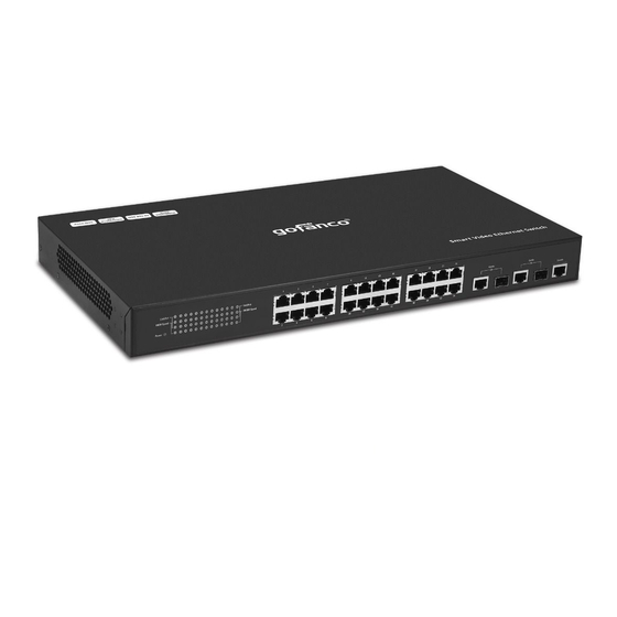
- Page 4 Product Layout Figure 1: Front Panel Layout Figure 2: Rear Panel Layout Power LED Power Indicator Indicators for network Speed and LEDs (x42) Link/Activity Connects to your TX and RX units RJ45 Ports (x24) using CAT cables Connects to your PC's network port for Combo RJ45/SFP Web GUI control.
-
Page 5: Hardware Installation
Hardware Installation Connect the power cord to the switch, then plug the other end into a reliable power outlet. The Speed, Link/Act LEDs will illuminate for 3-4 seconds then go off and the Power LED will be On. Connect the CAT cables, the Link/Act LED will be blinking and the Speed LED is On for normal operation. - Page 6 Application Diagram One-to- many connection Figure 3: One-to-many...
- Page 7 Many-to-many connection Figure 4: Many-to-many...
- Page 8 Web GUI Login The default IP address of the switch is 192.168.168.254. Username: admin, Password: admin. Connect your computer to the switch's Port 25 or Port 26 using a CAT or SFP Fiber Optic (LC) cable. Only port 25 or port 26 can access the switch's web GUI.
- Page 9 Vlan Presetting Port Settings Select Port Settings in the Vlan Presetting menu. Select either Input or Output depending on your hardware connection. When the port is set to Input, it should be connected to a transmitter unit. When the port is set to Output, it should be connected to a receiver unit.
- Page 10 Output Settings Select Preset Setting in the Vlan Presetting menu. The input ports are listed on the left side column. Select an Output port to display from an Input port. In the example below Port 2 will display video signal from Input Port 1, Port 4 will display video signal from Input Port 3, Port 6 will display video signal from Input Port 5, and Port 8 will display video signal from Input Port 7...
- Page 11 System Configuration User Management Use this to change the Switch's user name and password. Select User Management from the System Configuration menu. Enter your old and new personal information. Click Apply to save the changes. IP Basic Configuration Use this to change the Switch's IP address. Select IP Address Configuration from the IP Basic Configuration menu.
- Page 12 Upgrade Firmware Use this to update the Switch's firmware. Select File Upload from the System Configuration menu. Click Choose File, and enter firmware file. Click Click Upload. During the update process do not turn off the switch or interrupt the update process in any way.
- Page 13 Restart Switch Use this to restart the Switch. Select System Reset from the System Configuration menu. Click Reset. Click OK to restart the switch.
- Page 14 Blank Page...
- Page 15 Disclaimer The product name and brand name may be registered trademarks of related manufacturers. TM and ® may be omitted on the user's guide. The pictures on the user's guide are just for reference, and there may be some slight differences with the actual products.
- Page 16 Thank you for choosing gofanco www.gofanco.com...
Need help?
Do you have a question about the EthSwitch24P-2 and is the answer not in the manual?
Questions and answers