
Related Manuals for Peri RCS P


Summary of Contents for Peri RCS P
- Page 1 Rail Climbing System RCS P Climbing Protection Panel Instructions for Assembly and Use – Standard Configuration – Issue 01 | 2019...
- Page 2 Crossbar RCS 103 (concealed) Diagonal Strut RCS 212 Enclosure Beam Enclosure Working Platform Foldable Cover Climbing Shoe RCS Slab Shoe RCS Slab Anchor Template 61 RCS Climbing Device RCS 50 RCS P Climbing Protection Panel Instructions for Assembly and Use – Standard Configuration...
-
Page 3: Table Of Contents
Removing the Climbing Enclosure Assembly Dismantling the Climbing Enclosure C1 Pre-Assembly of Brackets General Components Preparation of the Climbing Rails Assembly of the Attachment Points Mounting the Climbing Rail Connector RCS P Climbing Protection Panel Instructions for Assembly and Use - Standard Configuration... -
Page 4: Overview
Consequences of non-compliance. ⇒ Avoidance measures. ⇒ Arrows Arrow representing an action Arrow representing a reaction of an action* Forces * if not identical to the action arrow. RCS P Climbing Protection Panel Instructions for Assembly and Use – Standard Configuration... -
Page 5: Introduction
– Lifting Beam RCS 9 t Product approvals: ƒ – Z-21.6-1766 PERI Screw-On Cone – Z-21.6-1767 PERI Climbing Cone Separate design information ƒ Design Tables 2015 – Formwork and Shoring ƒ RCS P Climbing Protection Panel Instructions for Assembly and Use – Standard Configuration... -
Page 6: Intended Use
Rail Climbing System LPS as a Climbing System. ture by means of Climbing Shoes and Climbing Protection Panel. The Climbing Protection Panel RCS P is Slab Shoes. The top Climbing Rail is a bracket-type framework construction offset and supports the enclosure... -
Page 7: Cleaning And Maintenance Instructions
- slipping hazard! Never clean powder-coated compo- Any repairs to PERI products are to be nents, e.g. elements and accessories, carried out by qualified PERI personnel with a steel brush or hard metal scrap- only. -
Page 8: Safety Instructions
Assembly and Use sup- required in these Instructions for As- the safety of the formwork system, the plied by PERI are available at all times sembly and Use, as well as all valid contractor must immediately and understood by the site personnel. - Page 9 ƒ safety shoes, ƒ safety gloves, ƒ safety glasses, ƒ is available and used as intended. RCS P Climbing Protection Panel Instructions for Assembly and Use – Standard Configuration...
-
Page 10: System-Specific
Repairs are only allowed to be car- ƒ of fall arrest equipment is deemed to condition are to be used. ried out by PERI qualified personnel. be inappropriate, personal protection In the case of overloading or recur- ƒ equipment (PPE) can be used if suita-... - Page 11 The access areas on the construction ures. site must be free of obstacles and trip- ping hazards, as well as being slip-re- sistant. RCS P Climbing Protection Panel Instructions for Assembly and Use – Standard Configuration...
-
Page 12: Storage And Transportation
When climbing with the hydraulic in place to secure those persons work- climbing device, specifications regard- Use PERI lifting accessories and slings ing at the falling edge, e.g. personal ing the arrangement of the hydraulic and only those load-bearing points pro- protective equipment against falling hoses are to be observed. - Page 13 RCS P Climbing Protection Panel Instructions for Assembly and Use – Standard Configuration...
-
Page 14: Component Overview And Tool List
Bolt ISO 4014 M24 x 130-8.8 109612 114113 Climbing Shoe RCS Hex. Nut ISO 7042 M24-8 105032 109468 Slab Shoe RCS 109567 Nut ISO 4032 M12-8 710330 RCS P Climbing Protection Panel Instructions for Assembly and Use – Standard Configuration... - Page 15 124777 Tightening torque Tool name For non-defined lubricated screw connections, Ratchet Wrench PERI recommends the following guide values as Extension for the Ratchet Wrench “hand-tightened“ tightening torque M Spirit Level These guide values are based on EN 15048 with Safety Factor 3 against breakage of a bolt with Cordless Screwdriver Strength Class 4.6.
-
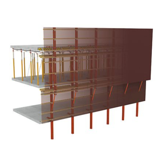
Page 16: A1 System Overview
Assembly of the climbing enclosure Fig. A1.01 varies depending on the storey height, projection of the slab formwork and type of anti-fall protection used. RCS P Climbing Protection Panel Instructions for Assembly and Use – Standard Configuration... - Page 17 Timber Fixation RCS 12/20 Enclosure Beam (timber) Enclosure (multi-layer plywood sheeting) Working platform decking Girder (timber) Foldable Cover Climbing Shoe RCS Slab Shoe RCS Anchoring Fig. A1.02 RCS P Climbing Protection Panel Instructions for Assembly and Use – Standard Configuration...
- Page 18 Bolt ISO 4014 M24 x 130-8.8 see Details of Support Nut ISO 4032 M12-8 and Working Platform 120 Heavy-Duty Spindle SLS 100/180 see Details of Foldable Cover Fig. A1.03 RCS P Climbing Protection Panel Instructions for Assembly and Use – Standard Configuration...
- Page 19 A1 System Overview Version 4 Details of Support and Working Platform 90 / 91 13.1 39 36 90 / 91 Fig. A1.05 Details of Foldable Cover Fig. A1.04 RCS P Climbing Protection Panel Instructions for Assembly and Use – Standard Configuration...
-
Page 20: A2 Climbing Device And Hydraulics
Contact PERI! 1* safety components. RCS P Climbing Protection Panel Instructions for Assembly and Use – Standard Configuration... - Page 21 63.9 Inflow to the piston head side of the cylinder with hydraulic quick coupler (nipple) 63.10 Rotary field control lamp 63.7 63.4 Fig. A2.03 63.1 63.8 63.9 63.10 63.2 63.3 Fig. A2.03a RCS P Climbing Protection Panel Instructions for Assembly and Use – Standard Configuration...
- Page 22 61.4 Hydraulic Quick Coupler (nipple) 61 / 62 Fig. A2.06 During transport, join the two coupling ends together to protect the hoses. 61.3 Fig. A2.07 61.4 1* safety components. RCS P Climbing Protection Panel Instructions for Assembly and Use – Standard Configuration...
-
Page 23: A3 Operating Status And Loads
150 kg/m² of more than 100 km/h is assumed, Working platform* 150 kg/m² additional safety measures on all Finishing platform* 75 kg/m² corner elements are required. *if mounted RCS P Climbing Protection Panel Instructions for Assembly and Use – Standard Configuration... -
Page 24: A4 Operating Sequence
Climbing enclosure is in position. Erect slab formwork with stopends. Close cover flaps. Install leading anchor with the aid of Concrete the columns. the Slab Anchor Template. RCS P Climbing Protection Panel Instructions for Assembly and Use – Standard Configuration... - Page 25 Strip slab formwork and back-prop. Rework slab. Open cover flaps. Assemble subsequent guardrails. Climb climbing enclosure hydraulically (as depicted above) or by crane. Dismantle bottom Slab Shoe. RCS P Climbing Protection Panel Instructions for Assembly and Use – Standard Configuration...
- Page 26 Climbing enclosure is in position. Erect slab formwork with stopends. Close cover flaps. Install leading anchor with the aid of Concrete the columns. the Slab Anchor Template. RCS P Climbing Protection Panel Instructions for Assembly and Use – Standard Configuration...
- Page 27 Open cover flaps. Rework slab. Climb climbing enclosure hydraulically Remove bottom slab formwork and (as depicted above) or by crane. back-prop. Dismantle bottom Slab Shoe. Assemble subsequent guardrails. RCS P Climbing Protection Panel Instructions for Assembly and Use – Standard Configuration...
-
Page 28: B1 Planning The Supporting Structure
Climbing Rails max. h 7.48 m 7.20 m 3.60 m 9.98 m 9.70 m 4.85 m RCS P Climbing Protection Panel Instructions for Assembly and Use – Standard Configuration... - Page 29 Enclosure Post RCS (1) ≥ h Calculation: Version 4 (Fig. B1.04) Climbing Rail RCS (2) with projecting protection panel. ≥ h + 28 cm. Fig. B1.04 Fig. B1.03 RCS P Climbing Protection Panel Instructions for Assembly and Use – Standard Configuration...
-
Page 30: Framework Assembly
Platform Beam and as a diagonal truss strut. In the arrangement shown, a Spacer ƒ must be moved in the Climbing Rail. See Section "Additional Spacers" on page 32. RCS P Climbing Protection Panel Instructions for Assembly and Use – Standard Configuration... - Page 31 No offset of the Spacers (A) in the ƒ Climbing Rail and Enclosure Post. With the arrangement of the ƒ Diagonal Struts shown, Spacers do not have to be removed. 70.8 Fig. B1.05 RCS P Climbing Protection Panel Instructions for Assembly and Use – Standard Configuration...
-
Page 32: Additional Spacers
50 cm. This ensures a definite bearing on the planned Slab Shoe without having to deactivate the other Slab Shoes. Fig. B1.06 Fig. B1.07 RCS P Climbing Protection Panel Instructions for Assembly and Use – Standard Configuration... -
Page 33: Additional Finishing Platforms
If only a short extension of Enclosure Post 1 is required, the finishing plat- form can be suspended by means of a Climbing Rail Extension 100 RCS (21). (Fig. B1.08) Fig. B1.08 RCS P Climbing Protection Panel Instructions for Assembly and Use – Standard Configuration... - Page 34 (6) (L = 3.48 m). Attach Climbing Rails with Climbing Rail Connectors RCS 33 (22) to Enclo- sure Post 1. (Fig. B1.09) 5 / 6 Fig. B1.09 RCS P Climbing Protection Panel Instructions for Assembly and Use – Standard Configuration...
-
Page 35: Reaction Forces
= q(z) x χ x c q(z) = peak velocity pressure = aerodynamic pressure coefficient = aerodynamic force coefficient = service life factor for temporary constructions χ RCS P Climbing Protection Panel Instructions for Assembly and Use – Standard Configuration... - Page 36 – The contractor is responsible for the correct transfer of the reaction forces into the building structure. RCS P Climbing Protection Panel Instructions for Assembly and Use – Standard Configuration...
-
Page 37: Suspension With The Slab Shoe
The Slab Anchor Template with the support plate rests on the stopend formwork. Fig. B1.13 The stop on the support plate creates an impression in the concrete. Fig. B1.14 RCS P Climbing Protection Panel Instructions for Assembly and Use – Standard Configuration... - Page 38 (Fig. B1.15) Components 47.1 Screw-On Cone-2 M24/DW 20 47.2 47.1 47.2 Threaded Anchor Plate DW 20 Approval No. Z-21.6-1766 or expert's report for the PERI Climbing Anchor. Fig. B1.15 Version 2: with Climbing Cone-2 M24/DW 15. (Fig. B1.17) Components 47.5 Climbing Cone-2 M24/DW 15 1* 47.6 Tie Rod DW 15 1* 2* or...
- Page 39 47.8 Spacer Tube Ø 22, LT = h - 185 mm 2* Approval No. Z-21.6-1767 or expert's report for the PERI Climb- ing Anchor. – With Tie Rod B15 (with circumferen- tial thread), the load-bearing capacity...
-
Page 40: Suspension With The Slab Stopend Shoe
Reducing Bushing Ø 30 - 25 Stopend Slab Anchor M24/20-128 Alternatively: 48.1 Climbing Cone-2 M24/DW 15 Tie Rod DW 15 or B15 Threaded Anchor Plate DW 15 Fig. B1.20 RCS P Climbing Protection Panel Instructions for Assembly and Use – Standard Configuration... -
Page 41: Horizontal Support
Fitting Pin Ø 21 mm Fitting Pin Ø 26 mm 120 Heavy-Duty Spindle SLS 100/180 121 Spindle Shoe SLS/RCS M24 45.2 Bolt ISO 4014 M24 x 70-10.9 Anchoring Fig. B1.22 RCS P Climbing Protection Panel Instructions for Assembly and Use – Standard Configuration... -
Page 42: B2 Planning The Units
2.5 t (8) ƒ planned to ensure that there is secure Girder (40) as compression brace access to all climbing units at all times. (Fig. B2.01) RCS P Climbing Protection Panel Instructions for Assembly and Use – Standard Configuration... - Page 43 With heavy climbing units where a ƒ load of more than 25 kN per attach- ment point must be lifted, attach the PERI Lifting Beam RCS 9t to a Spacer. α α (Fig. B2.01) – Follow Instructions for Use at all times! –...
-
Page 44: Planking
Components Enclosure Post Climbing Rail Crane Eye BR-2 2.5 t Working platform decking (planks) Toeboard 39.1 Angle Bracket 90° Girder (timber) Fig. B2.03 TSS-Torx 6 x 80 RCS P Climbing Protection Panel Instructions for Assembly and Use – Standard Configuration... -
Page 45: Girders
Max. width of influence (eB) of the Girder 0.50 m Working platform load according to Scaffold Group 2: Max. live load 150 kg/m² Max. cantilever d ≤ 0.5 · c Fig. B2.05 RCS P Climbing Protection Panel Instructions for Assembly and Use - Standard Configuration... -
Page 46: Protection Against Falling Objects
Cover RCS 70 x 70 Steel Scaffold Tube Ø 48.3 x 3.2 137 Scaffold Tube Connector Ø RCS 138 Flap Hinge LPS D48/M10 139 Flap Safety Plate LPS D=48 RCS RCS P Climbing Protection Panel Instructions for Assembly and Use – Standard Configuration... - Page 47 (18.1) or trapezoidal metal sheets (19). Components Enclosure Beam (timber) Enclosure (multi-layer plywood sheeting) Enclosure (trapezoidal metal sheeting) Protection Edge Fig. B2.09 RCS P Climbing Protection Panel Instructions for Assembly and Use - Standard Configuration...
- Page 48 – handrail boards – galvanised Steel Scaffold Tubes Ø 48.3 or Ø 60.3 – timbers with enclosure made of netting, tarpaulin, plywood or trape- zoidal metal sheeting Fig. B2.10 RCS P Climbing Protection Panel Instructions for Assembly and Use – Standard Configuration...
-
Page 49: Guardrails
Scaffold Tubes or supported to prevent any overloading. Components Steel Scaffold Tube Ø 48.3 x 3.2 Clamp A64 DIN 3570 Fig. B2.11 Hex. Nut ISO 4032 M12-8 Fig. B2.12 RCS P Climbing Protection Panel Instructions for Assembly and Use – Standard Configuration... - Page 50 Bolt ISO 4014 M24 x 130-8.8 Hex. Nut ISO 7042 M24-8 Hex. Nut ISO 4032 M12-8 Washer ISO 7093 200HV, A12 TSS-Torx 6 x 80 TSS-Torx 6 x 60 RCS P Climbing Protection Panel Instructions for Assembly and Use – Standard Configuration...
-
Page 51: Enclosure
Version 2 with trapezoidal sheeting Weight max. 15 kg/m² (Fig. B2.15 + B2.15a) The enclosure should completely enclose the working area. 90 / 91 19.1 Fig. B2.15 Fig. B2.15a RCS P Climbing Protection Panel Instructions for Assembly and Use - Standard Configuration... -
Page 52: B3 Corner Platforms
If necessary, measure and arrange edging reinforce- ment in the slab. Anchoring applicable for c1: Screw-On Cone, Cimbing Cone 3210 mm. RCS P Climbing Protection Panel Instructions for Assembly and Use - Standard Configuration... -
Page 53: External Corners
≥ 400 mm. (Fig. B3.02) At the corner of the building: a cross- wise arrangement of the Slab Shoe RCS (45) and Slab Shoe Corner RCS (46). (Fig. B3.01) Fig. B3.01 RCS P Climbing Protection Panel Instructions for Assembly and Use – Standard Configuration... - Page 54 (Fig. B3.03) Components Enclosure Beam (timber) Toeboard 1138 mm 39.1 Angle Bracket 90° Girder (timber) Slab Shoe RCS Fig. B3.03 Slab Shoe RCS Corner RCS P Climbing Protection Panel Instructions for Assembly and Use – Standard Configuration...
- Page 55 Fig. B3.04 14.1 Components Enclosure Beam (timber) 14.1 Bracing (multi-layer plywood sheeting) Toeboard 39.1 Angle Bracket 90° Girder (timber) Slab Shoe RCS Fig. B3.05 Slab Shoe RCS Corner RCS P Climbing Protection Panel Instructions for Assembly and Use – Standard Configuration...
- Page 56 Cone, Cimbing Cone 320 mm. (Fig. B3.06) 51 / 52 1138 mm Fig. B3.06 Components Stopend Slab Shoe RCS Stopend Slab Anchor M30/25- Stopend Slab Anchor M24/20- RCS P Climbing Protection Panel Instructions for Assembly and Use – Standard Configuration...
- Page 57 Standard Coupling NK 48/48 Guardrails L-Angle RCS Bolt ISO 4017 M12 x 140-8.8 Nut ISO 4032 M12-8 Washer ISO 7093 200HV, A12 Fig. B3.08 TSS-Torx 6 x 60 RCS P Climbing Protection Panel Instructions for Assembly and Use – Standard Configuration...
- Page 58 Ø 22 mm Take into consideration the technical Ø 30 mm documentation of the dowel that has been used! Fig. B3.08a Fig. B3.08c 230 mm Fig. B3.08b Fig. B3.08d RCS P Climbing Protection Panel Instructions for Assembly and Use – Standard Configuration...
-
Page 59: Internal Corners
Cover the gap between the mi- 50 mm tred enclosure elements. (Fig. B3.09) Components 39.1 Enclosure Beam (timber) Toeboard 39.1 Angle Bracket 90° Girder (timber) Fig. B3.09 RCS P Climbing Protection Panel Instructions for Assembly and Use - Standard Configuration... -
Page 60: Non Right-Angled Building Corners
Cover the gap between the mitred enclosure elements. (Fig. B3.10) Components Enclosure Beam (timber) Girder (timber) Slab Shoe RCS Slab Shoe RCS Corner RCS P Climbing Protection Panel Instructions for Assembly and Use – Standard Configuration... - Page 61 Depending on the assumed wind load, additional transverse bracing may be required. Components Enclosure Beam (timber) 14.1 Multi-layer plywood sheeting Girder (timber) Slab Shoe RCS Slab Shoe RCS Corner Fig. B3.11 RCS P Climbing Protection Panel Instructions for Assembly and Use – Standard Configuration...
-
Page 62: B4 Special Applications
Enclosure Beam (timber) be clearly dimensioned. Working platform decking Ensure covering for the gaps cannot Slab Shoe RCS move out of position. Fig. B4.01 Fig. B4.01a Fig. B4.01b RCS P Climbing Protection Panel Instructions for Assembly and Use – Standard Configuration... -
Page 63: Anchoring On Columns Or Walls
Adapt foldable covers to suit the build- ing columns. Close remaining gaps with cover mat and cover strip. Fig. B4.02 Top edge of slab 47.10 47.2 47.9 59.1 Fig. B4.02a Fig. B4.02b RCS P Climbing Protection Panel Instructions for Assembly and Use – Standard Configuration... -
Page 64: Anchoring On The Front Side Of The Slab
Bolt ISO 4017 M30 x 70-8.8 Reducing Bushing Ø 30 - 25 Stopend Slab Anchor M30/25- Stopend Slab Anchor M24/20- Bolt ISO 4014 M24 x 70-10.9 Slab Prop RCS P Climbing Protection Panel Instructions for Assembly and Use – Standard Configuration... - Page 65 (max. 30 mm), then the slab edge has to be supported sep- arately. PERI recommends a steel plate to be securely fixed to the head of a prop (89) and positioning it at the slab edge. Hole diameter in the plate 13 mm, hole arrangement depends on the type of slab prop used.
-
Page 66: C1 Pre-Assembly Of Brackets
Climbing Bolt in the Climbing Rail, see "Additional Spacers" on Page 32. Components Spacer M20-82 Spacer Tube Ø26.9×2.6 82 Bolt ISO 4014 M20 x 120-8.8 Nut ISO 7042 M20-8 RCS P Climbing Protection Panel Instructions for Assembly and Use - Standard Configuration... - Page 67 Spacers in the Climbing Rail. After mounting the additional Spacer, re-tighten all previously loos- ened bolts. Tightening torque min. 60 Nm. Have the nuts (3.3) been tightened? RCS P Climbing Protection Panel Instructions for Assembly and Use - Standard Configuration...
- Page 68 It may be necessary to release adjacent Spacers in the Climbing Rail. After mounting the additional Spacer, re-tighten all previously loosened bolts. Tightening torque min. 150 Nm. RCS P Climbing Protection Panel Instructions for Assembly and Use – Standard Configuration...
-
Page 69: Assembly Of The Attachment Points
2.5 t: max. 25 kN. For moving heavy climbing units, use Lifting Beam 9 t. Use a Spacer as an attachment point. Fig. C1.03a Follow Instructions for Use at all times! RCS P Climbing Protection Panel Instructions for Assembly and Use – Standard Configuration... - Page 70 Permissible load per Crane Eye BR-2 2.5 t: max. 25 kN. For moving heavy climbing units, use Lifting Beam 9 t. Follow Instructions for Use at all times! Fig. C1.04a RCS P Climbing Protection Panel Instructions for Assembly and Use - Standard Configuration...
-
Page 71: Mounting The Climbing Rail Connector
1.4) into the Climbing Rail Connector and connect with 2x fitting pins Ø 21 in holes Ø 21. Fig. C1.05a 4. Secure all fitting pins with cotter pins (26). RCS P Climbing Protection Panel Instructions for Assembly and Use – Standard Configuration... -
Page 72: Assembly Of The Bracket Framework
J The axial dimension of the Climb- ing Rails is fixed. J The Enclosure Beam also acts si- multaneously as anti-tilt protection for bracket units. (Fig. C1.06 + C1.06a) Fig. C1.06a RCS P Climbing Protection Panel Instructions for Assembly and Use – Standard Configuration... - Page 73 (Fig. C1.07 + C1.07a) Depending on the work organisation, pre-assembled working platforms can be mounted up to the outer Decking Transom. Fig. C1.07a RCS P Climbing Protection Panel Instructions for Assembly and Use – Standard Configuration...
- Page 74 4. Fold down bottom Diagonal Strut (12) and secure with bolt (94) and nut (95) to the Enclosure Post (1.2). (Fig. C1.08 + C1.08a) Fig. C1.08a RCS P Climbing Protection Panel Instructions for Assembly and Use – Standard Configuration...
- Page 75 For fixing, mount diagonal bracing if necessary. J The Bracket Framework Version 2 has now been mounted. (Fig. C1.09) Fig. C1.09 Fig. C1.09a RCS P Climbing Protection Panel Instructions for Assembly and Use – Standard Configuration...
-
Page 76: Overview Of The Bracket Framework
Bolt ISO 4014 M24 x 130-8.8 Hex. Nut ISO 7042 M24-8 94 + 95 94 + 95 94 + 95 Fig. C1.11a Fig. C1.11b (748) 998 Fig. C1.11 RCS P Climbing Protection Panel Instructions for Assembly and Use – Standard Configuration... - Page 77 1.3 / 1.4 748 / (998) Fig. C1.12 Version 4 Components Climbing Rail RCS 348 Climbing Rail RCS Climbing Rail Connector RCS 73 748 / 998 Fig. C1.13 RCS P Climbing Protection Panel Instructions for Assembly and Use – Standard Configuration...
-
Page 78: C2 Assembly Of The Working Platforms
(97) through the hole in the timber and Crossbar, and tighten with nut (96). For the bolt M12 x 240, the maximum clamping length is a = 220 mm. (Fig. C1.07) RCS P Climbing Protection Panel Instructions for Assembly and Use – Standard Configuration... -
Page 79: Mounting The Platform Decking And Toeboards
Requirements for decking and Toe- 39.1 boards, see Section "B2 Planning of the Units". Fig. C2.02 RCS P Climbing Protection Panel Instructions for Assembly and Use – Standard Configuration... -
Page 80: Foldable Cover
(150) with cam nuts into both Climbing Rails. The re- inforcing bar on the outer side must not project over the enclosure. (Fig. C2.03 + C2.03a) Fig. C2.03a RCS P Climbing Protection Panel Instructions for Assembly and Use – Standard Configuration... - Page 81 Flap Safety Plate (42) ap- proximately in the centre using 2 SPAX Screws TX 30 8x20. Foldable cover is now secured. (Fig. C2.04) Fig. C2.04 RCS P Climbing Protection Panel Instructions for Assembly and Use – Standard Configuration...
- Page 82 3. Secure the support (14.1) with screws 6 x 120 (111) at a distance of approx. 60 cm to the Enclosure Fig. C2.05 Beam (14). (Fig. C2.05) RCS P Climbing Protection Panel Instructions for Assembly and Use – Standard Configuration...
- Page 83 Secure each Fixation Bar to the en- closure using 4 screws 5 x 20 (109). The position is given in the pro- ject-specific planning documents. Fig. C2.06 41.1 Fig. C2.06a Fig. C2.07 RCS P Climbing Protection Panel Instructions for Assembly and Use – Standard Configuration...
-
Page 84: C3 Assembly Of The Enclosure
Drilled hole Bolt Ø 26 mm M24 x 130 (94) M24-8 (95) Climbing Rail Enclosure Post Ø 20 mm M20 x 120 (92) M20-8 (93) Table C3.01 RCS P Climbing Protection Panel Instructions for Assembly and Use – Standard Configuration... -
Page 85: Mounting The Enclosure Beam
140 (90) or M12 x 240 (91) through the holes of the Timber Fixation and Enclosure Beam. Secure bolt with washer (97) and nut (96). (Fig. C3.01) RCS P Climbing Protection Panel Instructions for Assembly and Use – Standard Configuration... - Page 86 Drilled hole Bolt Ø 26 mm M24 x 130 (94) M24-8 (95) Climbing Rail Enclosure Post Ø 20 mm M20 x 120 (92) M20-8 (93) Table C2.01 RCS P Climbing Protection Panel Instructions for Assembly and Use – Standard Configuration...
- Page 87 Ø 7 mm. Do not pre-drill the Enclo- sure Beam. 4. Align the multi-layer plywood sheet- ing and secure on the Enclosure Beam using Torx screws (99). (Fig. C3.05 + C3.05a) RCS P Climbing Protection Panel Instructions for Assembly and Use – Standard Configuration...
-
Page 88: Cover: Version 1
6 x 60 (99). (Fig. C3.06) 5. Pre-drill cover sheet (18b) and fix to Fig. C3.06a timbers (87 + 87a) using screws 6 x 60 (99). (Fig. C3.06a) RCS P Climbing Protection Panel Instructions for Assembly and Use – Standard Configuration... -
Page 89: Mounting The Trapezoidal Metal Sheeting
Enclosure Beam using connection means recommended by the trapezoidal sheeting manufacturer. 4. Cover the cavities between the timber and trapezoidal sheeting, e.g. with Elastomer cover strip. (Fig. C3.07 + C3.07a) RCS P Climbing Protection Panel Instructions for Assembly and Use – Standard Configuration... -
Page 90: Mounting The Protection Edges
Fig. C3.08a front side of the Enclosure Beam (14) with screws 6 x 60 (99). Use 2 screws per Enclosure Beam. (Fig. C3.08 - C3.08c) Fig. C3.08b RCS P Climbing Protection Panel Instructions for Assembly and Use – Standard Configuration... -
Page 91: Scaffold Tubes With Nets Or Tarpaulins
4. Mount Scaffold Tube Ø 48 mm (80) in the tube coupling. Tighten coupling nut with 50 Nm. (Fig. C3.09) Fig. C3.09 137.2 137.1 137.3 Fig. C3.09a RCS P Climbing Protection Panel Instructions for Assembly and Use – Standard Configuration... - Page 92 2. Ensure bottom edge of the safety nets reach to the building. 3. Ensure there is a sufficient overlap with other enclosure parts. 80.1 80.2 83.1 Fig. C3.09b RCS P Climbing Protection Panel Instructions for Assembly and Use – Standard Configuration...
- Page 93 RCS P Climbing Protection Panel Instructions for Assembly and Use – Standard Configuration...
-
Page 94: C4 Suspension On The Structure
5. Attach guide ropes to the climbing Fig. C4.01 enclosure. 6. Attach crane lifting gear to the bolt. 7. Align and lift the Climbing Unit. (Fig. C4.02) RCS P Climbing Protection Panel Instructions for Assembly and Use – Standard Configuration... -
Page 95: Assembly Of The Climbing Unit
= n x 50 cm. 5. Activate the climbing pawl of the top Climbing Shoe. See Section "Activat- ing and Deactivating the Climbing Pawl" on Page 122 (Fig. C4.03). Fig. C4.03 RCS P Climbing Protection Panel Instructions for Assembly and Use – Standard Configuration... - Page 96 Rail Guidance Shoe" on Page 110. 3. Remove the Guide-In Tool (126). 4. Place the climbing enclosure with Spacer (3) on the climbing pawl (44.1). (Fig. C4.04b) Fig. C4.04 RCS P Climbing Protection Panel Instructions for Assembly and Use – Standard Configuration...
- Page 97 Slab Shoe. (Fig. C4.05 + C4.05a) 10. Completely relieve crane and release crane lifting gear whilst standing in a safe position. 44.6 44.1 44.2 Fig. C4.05 Fig. C4.05a RCS P Climbing Protection Panel Instructions for Assembly and Use – Standard Configuration...
- Page 98 Fixation Bar to the enclosure using 4 screws 5 x 20 (109). 3. If necessary, carry out adjustments, e.g. in the area of the Climbing Shoes. (Fig. C4.06) RCS P Climbing Protection Panel Instructions for Assembly and Use – Standard Configuration...
- Page 99 Cover any remaining gaps with suitable means, e.g. Elastomer cover strips. Make sure that neither the climbing procedure nor the opening of the flaps is impaired in any way. Fig. C4.07 RCS P Climbing Protection Panel Instructions for Assembly and Use – Standard Configuration...
-
Page 100: Troubleshooting
– Floor height is approx. a multiple of the pawls of all Slab Shoes posi- 50 cm. tioned above. Position Climbing Unit with the planned Spacer on the pawl of the bottom Slab Shoe. RCS P Climbing Protection Panel Instructions for Assembly and Use – Standard Configuration... - Page 101 RCS P Climbing Protection Panel Instructions for Assembly and Use – Standard Configuration...
-
Page 102: D1 Suspension And Anchoring
Enclosure Post until it is in a hori- zontal position. 3. Tighten the bolted connection. (Tightening torque 120 Nm) 4. Tighten wing screws (54.1). (Fig. D1.01 + D1.02) 54.3 54.2 54.1 54.4 Fig. D1.02 RCS P Climbing Protection Panel Instructions for Assembly and Use – Standard Configuration... - Page 103 Drop the locking bar behind the mounting plate. The lock- ing bar (54.5) fixes the Slab Anchor Template in a vertical position. (Fig. D1.03b + D1.03) Fig. D1.03b RCS P Climbing Protection Panel Instructions for Assembly and Use – Standard Configuration...
- Page 104 + 150b) all the way up to the Climb- ing Cone (47.5) so that they touch it Fig. D1.04a on each side. Wire reinforcement bars to the slab reinforcement. (Fig. D1.04 + D1.04a) RCS P Climbing Protection Panel Instructions for Assembly and Use – Standard Configuration...
-
Page 105: Mounting The Stopend Slab Anchor
4. Bend over protruding nails immedi- ately after striking. 5. Loosen the advancing cap (51.1) by turning it counterclockwise and remove. J Anchoring point is now ready. RCS P Climbing Protection Panel Instructions for Assembly and Use – Standard Configuration... -
Page 106: Assembly Of The Suspension
Stopend Slab Shoe RCS Stopend Slab Anchor M30/25- Stopend Slab Anchor M24/20- Bolt ISO 4014 M24 x 70-10.9 Bolt ISO 4017 M30 x 70-8.8 151 PERI Anchor Bolt 14/20x130 RCS P Climbing Protection Panel Instructions for Assembly and Use – Standard Configuration... - Page 107 Slab Shoe: a = 600 mm, b = 100 mm, dx = 10 mm play Have all fixings been correctly Fig. D1.06 tightened? Fig. D1.06a RCS P Climbing Protection Panel Instructions for Assembly and Use – Standard Configuration...
- Page 108 (51/52) using bolt M30 x 70 (49) or bolt M24 (53) with the reducing bushing (50). 3. Remove guardrails. (Fig. D1.07) Have all fixings been correctly tightened? RCS P Climbing Protection Panel Instructions for Assembly and Use – Standard Configuration...
- Page 109 – Are all locking pins on the guide skids fully inserted and secured? – Are all locking pins of the Slab Shoes / Stopend Slab Shoes secured with Fig. D1.08a cotter pins? RCS P Climbing Protection Panel Instructions for Assembly and Use – Standard Configuration...
-
Page 110: Bracing The Corner Elements
Ø 21 x 120 (24) and cotter pin (26) whilst standing on the platform. 4. Connect Articulated Spanner (125) to the Bracing Shoe RCS DW15 (122) with the fitting pin. (Fig. D1.09b) Fig. D1.09 RCS P Climbing Protection Panel Instructions for Assembly and Use – Standard Configuration... - Page 111 Assembled or packaged on the plat- forms outside of the walkways. Secure bracing to prevent it falling to the ground. 230 mm Fig. D1.09c Ø 30 mm Fig, D1.09d Fig. D1.09e RCS P Climbing Protection Panel Instructions for Assembly and Use – Standard Configuration...
-
Page 112: Horizontal Support
3. Attach second Spindle Shoe (121b) to the Heavy-Duty Spindle (120) using fitting pin Ø 21 and cotter pin (26). (Fig. D1.10) Have all bolts been secured with cotter pins? RCS P Climbing Protection Panel Instructions for Assembly and Use – Standard Configuration... - Page 113 3. Fix Spindle Shoe (121b) in the hole Ø 26 of the Enclosure Post (1) using fitting pins Ø 21. (Fig. D1.10a) Fig. D1.10a Have all bolts been secured with cotter pins? RCS P Climbing Protection Panel Instructions for Assembly and Use – Standard Configuration...
- Page 114 Post using binding wire. (Fig. D1.11a) 24 + 26 48.1 Have all bolts been secured with cotter 25 + 27 pins? 24 + 26 Fig. D1.11a RCS P Climbing Protection Panel Instructions for Assembly and Use – Standard Configuration...
-
Page 115: Dismantling The Suspension
Slab Shoe. Supplement Toeboard after dismantling the Slab Shoe. Components Climbing Shoe RCS 44.1 Climbing Pawl Slab Shoe RCS 45.1 Locking Pin Bolt ISO 4014 M24 x 70-10.9 RCS P Climbing Protection Panel Instructions for Assembly and Use – Standard Configuration... - Page 116 5. Lift Slab Shoe RCS (45) and turn it inwards to a secure position. Fig. D1.12 6. Remove bolt M24 x 70. (Fig. D1.12b) Fig. D1.12a Fig. D1.12b RCS P Climbing Protection Panel Instructions for Assembly and Use – Standard Configuration...
-
Page 117: Removing The Anchoring
1. Release Screw-On Cone with socket wrench SW 36 and remove. 2. Close remaining hole with suitable KK Concrete Cone (47.9) and match- ing adhesive. (Fig. D1.13a) RCS P Climbing Protection Panel Instructions for Assembly and Use – Standard Configuration... - Page 118 1. Release Climbing Cone by means of Socket Wrench SW 36 and remove. 2. Close remaining hole with suitable KK Concrete Cone (47.9) and match- ing adhesive. (Fig. D1.13b) Fig. D1.13b RCS P Climbing Protection Panel Instructions for Assembly and Use – Standard Configuration...
- Page 119 Tie Rod DW 15 from below using a secured mobile scaf- fold. 4. Close remaining hole with suitable KK Concrete Cone (47.9) and match- ing adhesive. (Fig. D1.13c) RCS P Climbing Protection Panel Instructions for Assembly and Use – Standard Configuration...
-
Page 120: D2 Operating The Climbing Shoe
44.6 Opening the guiding skids facilitates in- serting the Climbing Rail during climb- ing and allows inserting the Climbing Rail during initial assembly. Fig. D2.03 Fig. D2.03a RCS P Climbing Protection Panel Instructions for Assembly and Use – Standard Configuration... - Page 121 Are both locking pins completely inserted and is the locking spring fixed in position? 44.2 44.2 Fig. D2.05 Fig. D2.05a 44.3 44.3 44.6 44.6 Fig. D2.06 Fig. D2.06a RCS P Climbing Protection Panel Instructions for Assembly and Use – Standard Configuration...
-
Page 122: Climbing Pawl
(Fig. D2.07 + D2.07a) In this position, no vertical forces from the Climbing Rail can be transferred via 44.5 this particular shoe. 44.4 Fig. D2.07a RCS P Climbing Protection Panel Instructions for Assembly and Use – Standard Configuration... - Page 123 50 cm, only activate the pawls on the Climbing Shoes that serve as the planned vertical support. Deactivate all other Climbing Shoes. 44.5 44.4 Fig. D2.08a RCS P Climbing Protection Panel Instructions for Assembly and Use – Standard Configuration...
-
Page 124: D3 Moving By Crane
Rail Guidance Shoes and may be necessary until they can be Climbing Rails while the climbing safely removed. enclosure is moving. RCS P Climbing Protection Panel Instructions for Assembly and Use – Standard Configuration... -
Page 125: Preparations
For operating the Climbing Shoes, see Section "Opening and Closing the Climbing Shoe" on Page 120 as well as Section "Activating and Deactivating the Climbing Pawl" on Page 122. Fig. D3.01 RCS P Climbing Protection Panel Instructions for Assembly and Use – Standard Configuration... -
Page 126: Moving Procedure
Slab Shoe (44b). 4. Activate pawl of the load-bearing Slab Shoe (44b). 5. Position Climbing Unit on the Spacer. Fig. D3.02 RCS P Climbing Protection Panel Instructions for Assembly and Use – Standard Configuration... -
Page 127: Troubleshooting
3. Dismantle trailing Slab Shoe, see Section "Dismantling the Suspen- sion" on page 115. 4. Remove anchoring that is no longer needed, see Section "Dismantling the Anchoring" on page 117. RCS P Climbing Protection Panel Instructions for Assembly and Use – Standard Configuration... -
Page 128: D4 Moving With The Climbing Device
– they do not get tangled with the climbing platforms. Up to 2 units can be climbed at the ƒ same time. RCS P Climbing Protection Panel Instructions for Assembly and Use – Standard Configuration... -
Page 129: Initial Operation Of The Climbing Hydraulics
Cylinder 3 Cylinder 4 Hose 10 m Hose 10 m Hose 20 m Hose 20 m A4, B4 A3, B3 A2, B2 A1, B1 Hydraulic pump Fig. D4.01 RCS P Climbing Protection Panel Instructions for Assembly and Use – Standard Configuration... -
Page 130: Moving Procedure
8. After the required protection height has been reached: – Stop the climbing procedure. – Position the Climbing Unit with Spacer on the middle Slab Shoes. Fig. D4.01 RCS P Climbing Protection Panel Instructions for Assembly and Use – Standard Configuration... -
Page 131: Self-Climbing Procedure
– Is the locking lever (60.6) fully engaged on the cylinder base? – No possibility of the hydraulic hoses becoming entangled? RCS P Climbing Protection Panel Instructions for Assembly and Use – Standard Configuration... - Page 132 Are all claws engaged in the Spacers? Fig. D4.03 If the Foldable Covers (41) collide with the hoses or hydraulic climbing device during opening: – Cut cover mat. RCS P Climbing Protection Panel Instructions for Assembly and Use – Standard Configuration...
- Page 133 – Load is carried by the climbing pawl (44.1) in the middle Slab Shoe (44b), – Claw is relieved of the Spacer. (Fig. D4.05) 44.1 Fig. D4.05 RCS P Climbing Protection Panel Instructions for Assembly and Use – Standard Configuration...
- Page 134 Climbing Unit is gradually climbed upwards in increments of 50cm. (Fig. D4.07) If the hydraulic hoses become taut or entangled, immediately stop the climbing procedure and eliminate the problem! Fig. D4.07 RCS P Climbing Protection Panel Instructions for Assembly and Use – Standard Configuration...
- Page 135 3. Close the guiding skids (44.2) of the top Climbing Shoe (44a). Deactivate the climbing pawls. 4. Remove Guide-in Tool. 5. Continue climbing procedure. (Fig. D4.08 + D4.08a) Fig. D4.08 44.2 Fig. D4.08a RCS P Climbing Protection Panel Instructions for Assembly and Use – Standard Configuration...
- Page 136 Climbing Shoes (44b) engage in the correct Spacers. (Fig. D4.09) Are the climbing pawls of all middle Climbing Shoes (44b) engaged? Fig. D4.09 RCS P Climbing Protection Panel Instructions for Assembly and Use – Standard Configuration...
-
Page 137: Finishing Tasks
Section "Dismantling the Suspen- sion" on page 115. 4. Remove anchoring that is no longer 60.6 needed, see Section "Dismantling the Anchoring" on page 117. Fig. D4.10a RCS P Climbing Protection Panel Instructions for Assembly and Use – Standard Configuration... -
Page 138: E Dismantling
Section "Assembly of Attachment Points" on page 69. 7. Attach guide ropes to the climbing enclosure. 8. Attach crane lifting gear to Crane Eye BR-2. (Fig. E.01) Fig. E.01 RCS P Climbing Protection Panel Instructions for Assembly and Use – Standard Configuration... - Page 139 6. Dismantle the remaining Slab Shoes (44b, 44c) and remove the anchoring. 7. Complete guardrails. (Fig. E.02) Fig. E.02 RCS P Climbing Protection Panel Instructions for Assembly and Use – Standard Configuration...
-
Page 140: Dismantling The Climbing Enclosure
1. Remove Enclosure Beams from the Enclosure Posts. 2. Remove Girders (40) from the Crossbars (10). 3. Remove Enclosure Posts (1) from both bracket units. (Fig. E.03 + E.04) Fig. E.04 RCS P Climbing Protection Panel Instructions for Assembly and Use – Standard Configuration... - Page 141 Fig. E.05 the next use due to displaced or additional Spacers. With rental equipment, PERI may in- ƒ voice the client for the costs incurred for the dismantling work. Non-reusable materials are to be ƒ...
- Page 142 RCS-P Item no. Weight kg Climbing Rails RCS 114166 78.200 Climbing Rail RCS 148 1480 109469 130.000 Climbing Rail RCS 248 2480 112102 156.000 Climbing Rail RCS 298 2980 109470 182.000 Climbing Rail RCS 348 3480 112141 209.000 Climbing Rail RCS 398 3980 109471 262.000...
- Page 143 RCS-P Item no. Weight kg 110569 16.700 Climbing Rail Hinge RCS Complete with For an articulated connection of the Climbing Rails 3 pc. 710894 Pin Ø 25 x 180, geomet. RCS and as pressure point on the RCS Climbing 4 pc. 018060 Cotter Pin 4/1, galv. Brackets.
- Page 144 RCS-P Item no. Weight kg 109743 6.370 Climbing Rail Connector RCS 33 Complete with For an articulated connection of Climbing Rails 3 pc. 710894 Pin Ø 25 x 180, geomet. RCS. 6 pc. 018060 Cotter Pin 4/1, galv. Ø25 123534 5.910 Brace Connector RCS DW 15/M20 Complete with...
- Page 145 RCS-P Item no. Weight kg 022230 0.033 Cotter Pin 5/1, galv. Ø5 Crossbar RCS 69 Complete with 111631 10.100 As horizontal bar or strut for assembly as Climbing 2 pc. 109612 Bolt ISO 4014 M24 x 130-8.8, galv. Protection Panel (platform width 1.00 m). 2 pc.
- Page 146 RCS-P Item no. Weight kg 110012 23.500 Diagonal Strut RCS 212 Complete with For bracing RCS Framework Brackets. 1 pc. 710894 Pin Ø 25 x 180, geomet. 1 pc. 018060 Cotter Pin 4/1, galv. 2 pc. 109612 Bolt ISO 4014 M24 x 130-8.8, galv. 1 pc.
- Page 147 RCS-P Item no. Weight kg 126430 4.460 Adapter VT 20 / RCS-P For mounting a horizontal positioned Girder VT 20 onto the Climbing Profile RCS. Accessories 024470 0.008 TSS-Torx 6 x 60, galv. 109612 0.600 Bolt ISO 4014 M24 x 130-8.8, galv. 105032 0.070 Nut ISO 7040 M24-8, galv.
- Page 148 RCS-P Item no. Weight kg Scaff. Tubes Steel 026415 3.550 Scaff. Tube Steel Ø 48.3 x 3.2, special length Cutting Cost Scaffold Tube 026417 0.000 026411 3.550 Scaff. Tube Steel Ø 48.3 x 3.2, l = 1.0 m 1000 026412 7.100 Scaff.
- Page 149 RCS-P Item no. Weight kg 111436 0.150 Hinge DIN 7957-200-ST, yellow galv. For mounting the cover flap at the climbing protection panel. Ø3,8 Accessories 111437 0.004 Spax Screw TX25, 5 x 20, yellow galv. 110642 0.006 Spax Screw TX25, 5 x 40, yellow galv. 114937 0.402 Fixation Bar RCS...
- Page 150 RCS-P Item no. Weight kg 109612 0.600 Bolt ISO 4014 M24 x 130-8.8, galv. SW 36 M 24 Nut ISO 7040 M24-8, galv. 105032 0.070 Self-locking. SW 36 TSS-Torxs, galv. 024470 0.008 TSS-Torx 6 x 60, galv. 024690 0.008 TSS-Torx 6 x 80, galv. For Torx Blade TX 30.
- Page 151 RCS-P Item no. Weight kg Lag Screws DIN 571 051640 0.014 Lag Screw DIN 571 6 x 80, galv. 024270 0.023 Lag Screw DIN 571 8 x 60, galv. F.H. Bolts DIN 603 051650 0.060 F.H. Bolt DIN 603 M6 x 180 MU, galv. 024140 0.033 F.H.
- Page 152 RCS-P Item no. Weight kg 113348 0.043 Washer ISO 7094 100 HV, A 12, galv. Lifting Beam 9 t Complete with 127320 158.000 For moving climbing units. 1 pc. 112865 Bolt 25 x 180 1 pc. 022230 Cotter Pin 5/1, galv. 1 pc.
- Page 153 RCS-P Item no. Weight kg 114317 3.210 Guide in Tool RCS For pulling up the Climbing Rail RCS in order to close the folding runners of the Climbing Shoe. 560 - 680 109468 19.800 Climbing Shoe RCS Complete with Guide and support for Climbing Rail RCS. With 2 pc.
- Page 154 RCS-P Item no. Weight kg 110375 30.800 Slab Shoe RCS Corner Complete with Anchor System M24. For mounting Climbing Shoe 1 pc. 715585 Pin Ø 25 x 240, SKS, galv. RCS to the corners of slab edges. 1 pc. 022230 Cotter Pin 5/1, galv. 115570 54.400 Slab Shoe Adjustable RCS 30...
- Page 155 RCS-P Item no. Weight kg 114947 12.600 Slab Anchor Template 61 RCS Complete with For positioning the Advancing Bolt M24 for the 1 pc. 115112 Wing-Bolt DIN 316 M12 x 25-GT, galv. Slab Shoe RCS. Fixed on the stopend formwork. 1 pc.
- Page 156 RCS-P Item no. Weight kg 115850 11.200 Slab Support Adapter RCS Complete with For attaching the Climbing Shoe RCS to a slab 1 pc. 111567 Fitting Pin Ø 26 x 120 support with horizontal Climbing Rail RCS. 1 pc. 715585 Pin Ø 25 x 240, SKS, galv. 2 pc.
- Page 157 Climbing Rail RCS. 1 pc. 022230 Cotter Pin 5/1, galv. Fixation with the Anchor Bolt 14/20 x 130 or the anchor system M24. Ø25,5 Accessories Anchor Bolt PERI 14/20 x 130 124777 0.210 Screw-On Cone-2 M24/DW 20, galv. Note 114158 1.030...
- Page 158 RCS-P Item no. Weight kg 031220 1.010 Climbing Cone-2 M24/DW 15, galv. Note Anchor System M24. Seperate design information on request. For anchoring climbing systems. SW 36 Accessories Threaded Anchor Plate DW 15 030840 0.515 030030 1.440 Tie Rod DW 15, spec. length 030740 1.550 Tie Rod B 15, spec.
- Page 159 RCS-P Item no. Weight kg 026430 0.334 Bolt ISO 4014 M24 x 70-10.9, glav. High-strength bolt for anchoring climbing systems. SW 36 Slab Stopend Shoe RCS Complete with 113232 10.500 For anchoring the Climbing Shoe RCS at the front 1 pc. 113247 Pin Ø 25 x 260, mont. end of the slab.
- Page 160 Stopend Slab Anchor M30/25-160 Note Tie System M24 or M30 for transferring clear ten- Permissible load: see PERI product information. sion forces into the slab with the use of Front Slab Shoe RCS. With Steckteller M24 (grey) and M30 (red).
- Page 161 RCS-P Item no. Weight kg 115378 1.080 Eye Nut RCS DW 15 As an articulated connection to the Climbing Rail RCS, Steel Waler SRU for bracing with DW 15. Ø26,5 DW 15 Accessories 104031 0.462 Fitting Pin Ø 21 x 120 Cotter Pin 4/1, galv.
- Page 162 Hydraulic Pump RCS 4-fold, 380 – 460 V Note Hydraulic pump for actuating the Climbing Device Follow Instructions for Use. RCS 50 and LPS 30. Use only original PERI Hydraulic Oil HV LP46. Accessories Hydraulic Oil ISO 11158 HVI46, 20 l 057376 18.300...
- Page 163 RCS-P Item no. Weight kg Hydraulic Twin Hoses RCS Complete with 110069 8.500 Hydraulic Twin Hose RCS, 10 m 2 pc. 128992 Pin ISO16028 DN10 R3/8IG 110070 15.300 Hydraulic Twin Hose RCS, 20 m 2 pc. 128993 Sleeve ISO16028 DN10 R3/8IG Two permanently connected hydraulic hoses for 4 pc.
- Page 164 RCS-P Item no. Weight kg 029610 5.300 Ratchet Wrench 1" Socket SW 19-1/2" 029620 0.075 Fits to Hex. Bolts M12 or Height Adjusting Unit SW 19. SW 19 057276 0.625 Socket SW 30-3/4" Fits to Hex. Bolts M20. SW 30 102785 0.452 Socket SW 36-3/4"...
- Page 165 RCS-P Item no. Weight kg Climbing Rail Profiles RCS 117585 24.300 Climbing Rail Profile RCS 98 Climbing Rail Profile RCS 148 116478 37.000 1480 116479 61.500 Climbing Rail Profile RCS 248 2480 116480 86.300 Climbing Rail Profile RCS 348 3480 Climbing Rail Profile RCS 398 113705 98.700...
- Page 166 RCS-P Item no. Weight kg 125632 0.050 Protect. Covers Climb. Device RCS Technical Data To protect unplugged quick couplings 1 set for 1 Climbing Device RCS 50 (2x bushing X-GE 12PSR-ED+ against dirt and damage. and 2x nipple each). Ø27,1 Ø23 110823 0.171...
- Page 167 RCS-P Item no. Weight kg Girder GT 24 075100 5.300 Girder GT 24, l = 0.90 m Girder GT 24, l = 1.20 m 075120 7.100 1214 075150 8.900 Girder GT 24, l = 1.50 m 1510 075180 10.600 Girder GT 24, l = 1.80 m 1806 Girder GT 24, l = 2.10 m 075210...
- Page 168 RCS-P Item no. Weight kg Girder VT 20K 074990 8.600 Girder VT 20K, l = 1.45 m 1447 Girder VT 20K, l = 2.15 m 074905 12.700 2152 074910 14.500 Girder VT 20K, l = 2.45 m 2452 074890 15.600 Girder VT 20K, l = 2.65 m 2652 Girder VT 20K, l = 2.90 m...
- Page 170 PERI (L.L.C.) TOO PERI Kazakhstan www.peri.ca www.peri.pt www.peri.ae www.peri.kz Mexico Algeria Azerbaijan Lebanon PERI Lebanon Sarl PERI Cimbras y Andamios, S.A. de C.V. S.A.R.L. PERI PERI Repesentative Office www.peri.com.mx www.peri.dz www.peri.com.tr lebanon@peri.de Panama Egypt Hong Kong Malaysia PERI Panama Inc.
- Page 171 PERI Australia Pty. Ltd. PERI Danmark A/S PERI S.r.l. PERI Sverige AB www.periaus.com.au www.peri.dk www.peri.it www.peri.se Estonia Lithuania Slovania PERI UAB PERI oplate i skele d.o.o PERI AS Europe www.peri.ee www.peri.lt www.peri.com.hr Albania Spain Luxembourg Slovakia PERI Kalıp ve İskeleleri PERI S.A.U.
- Page 172 Bridge Formwork Tunnel Formwork Shoring Systems Construction Scaffold Facade Scaffold Industrial Scaffold Access Protection Scaffold Safety Systems System-Independent Services Accessories PERI GmbH Formwork Scaffolding Engineering Rudolf-Diesel-Strasse 19 89264 Weissenhorn Germany Tel. +49 (0)7309.950-0 Fax +49 (0)7309.951-0 info @ peri.com www.peri.com...
Need help?
Do you have a question about the RCS P and is the answer not in the manual?
Questions and answers