
Related Manuals for Peri CB 240


Summary of Contents for Peri CB 240
- Page 1 CB 240 Climbing Formwork Instructions for Assembly and Use – Standard Configuration Edition 11 | 2014...
-
Page 2: Table Of Contents
Additional Technical Documentation Moving procedure Load Models Standard Work Flow C1 Planning and Work Preparation Static System A1 Assembly of the CB 240 Platform Platform Dimensioning Required Resources Platform Decking Assembly of CB 240 Brackets Handrails and Guardrails Girder Assembly... -
Page 3: Introduction
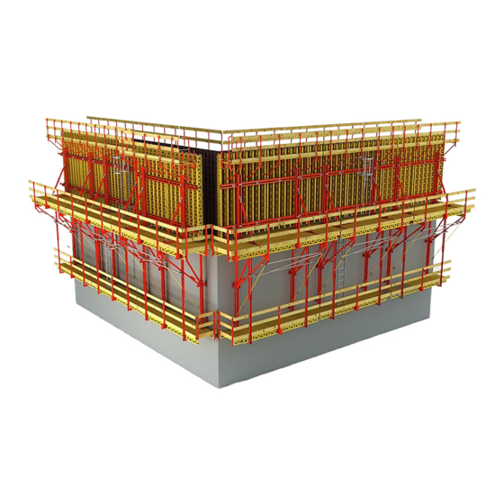
Introduction Overview, Main Components Concreting platform Climbing Formwork CB 240 with VARIO GT 24 Girder Wall Formwork – Concreting height 5.40 m. – Extended suspension of finishing platform. – Tension Anchor CB with DW 15 as wind bracing. – Intermediate platform on formwork. - Page 4 *Formwork height = concreting height + formwork projection (max. 5.40 m) Working platform 1 Working platform with Climbing Bracket CB 240 Finishing platform 2 Carriage CB 240 with Rack CB 240 3 Adjustable Brace CB 164-224 4 Strongback CB 270 or CB 380...
- Page 5 5.1 Screw-On Cone 2 M24/DW 20 5.6 Scaffold Mounting Ring M24, galv. 15,5 cm 5.7 Hex. Bolt M24 x 120 ISO 4014-10.9 Anchoring depth h = 15.5 cm (fix). * “Not re-usable” CB 240 Climbing Formwork Instructions for Assembly and Use – Standard Configuration...
-
Page 6: Key
The safety installations which have possibly not been shown in these de- tailed descriptions must nevertheless be available. Preceding working steps must be complied with. CB 240 Climbing Formwork Instructions for Assembly and Use – Standard Configuration... -
Page 7: Intended Use
VARIO and TRIO formwork sys- – max. formwork height: 5.40 m tems. The CB 240 climbing formwork system – a height-adjustable finishing platform is normally used as shoring in order to complete with access ladder which is support anchored wall formwork in ac- attached to posts. -
Page 8: General Safety Instructions
– Timber components: Strength Class Instructions for Assembly and Use provi- C24 for Solid Wood according to ded by PERI are available at all times for The contractor has to provide safe wor- EN 338. the users and that they are also fully un- king areas for site personnel which are –... -
Page 9: System-Specific Safety Instructions
Additional Technical Documentation – CB 240 Dimensioning Information – CB 240 Climbing scaffold type test – CB 240 and CB 160 Climbing System Brochures – Instructions for Use for the Crane Splice 24 – Instructions for Use: MAXIMO Lifting Hook –... -
Page 10: Load Models
Concreting platform 150 kg/m² Load Class 2 Working Position The area-related loads correspond to EN 12811. Working platform 200 kg/m² Load Class 3 300 kg/m Finishing platform 75 kg/m² Load Class 1 CB 240 Climbing Formwork Instructions for Assembly and Use – Standard Configuration... - Page 11 Load Models Concreting platform 150 kg/m² Load Class 2 Concreting Position The area-related loads correspond to EN 12811. Working platform 200 kg/m² Load Class 3 Finishing platform 75 kg/m² Load Class 1 CB 240 Climbing Formwork Instructions for Assembly and Use – Standard Configuration...
-
Page 12: Standard Work Flow
7 . Mount scaffold mounting rings. 16. Remove advancing bolts and retract 8. Attach platform unit. formwork. 9. Mount wind bracing if required. 17 . Mount scaffold mounting rings. CB 240 Climbing Formwork Instructions for Assembly and Use – Standard Configuration... - Page 13 21. If necessary, mount ladder. 26. Place formwork anchor. 31. Move climbing unit to next wall section. Continue with standard 27 . Pour wall section. cycle. 32. Dismantle the climbing unit. CB 240 Climbing Formwork Instructions for Assembly and Use – Standard Configuration...
-
Page 14: A1 Assembly Of The Cb 240 Platform
A1 Assembly of the CB 240 Platform Required Resources 82 mm 82 mm Equipment and Tools Hammer, wire pins, plumb line, 4 screw clamps with 300 mm clamping length, 2 stop bars circular saw, electric drill, HSS drill Ø 6 mm, Ø 8 mm, min. L = 180 mm 1,0 m 072180 Ratchet Wrench 1/2”... -
Page 15: Assembly Of Cb 240 Brackets
A1 Assembly of the CB 240 Platform Assembly of CB 240 Brackets Assembly 1. Check centre-to-centre spacing of brackets regarding the planned measurement, or measure spacing of climbing cones already cast in con- crete. 2. Adjust centre-to-centre spacing of bra- ckets to the support (0.2). -
Page 16: Girder Assembly
A1 Assembly of the CB 240 Platforms Girder Assembly When using PERI GT 24 girders, 13.2 strengthen them on both sides in the area of the brackets with plywood strips (13.2). (Fig. A1.09) Dimensions: thickness/width/height 13.1 27 x 120 x 300 mm. - Page 17 A1 Assembly of the CB 240 Platform Single Girder Position GT 24 Girder Timber – plywood or 3-ply board (13.2) – hex. wood screw 6 x 80 DIN 571 (13.3) 13.6 – timber 8/16 (13.6) 13.3 – GT 24 lattice girder (13.7) (Fig.
-
Page 18: Assembly Of Cb 240 Carriage
A1 Assembly of the CB 240 Platforms Assembly of CB 240 Carriage Assembly 1. Retract the wedge (2.2). 2. Insert rack (2.7) into the carriage (2.1). (Fig. A1.16) Fig. A1.16 3. Secure with wedge (2.2). (Fig. A1.17) 4. Remove lower-positioned bolts (2.4) and roller (2.3) from the carriage. - Page 19 A1 Assembly of the CB 240 Platforms Assembly of CB 240 Carriage Assembly 6. Position carriage (2.1) on the bracket (1.1). (Fig. A1.19) The mounting for the Strongback is facing the formwork side. Fig. A1.19 7 . Push roller (2.3) on bolt (2.4). On the guardrail side, insert and secure...
-
Page 20: Assembly Of Decking For The Working Platform
A1 Assembly of the CB 240 Platforms Assembly of Decking for the Working Platform Assembly 1. Cut planking at right angles, L = 2.326 m. 2. At platform ends, fix each plank flush to the girders (13.1). (Fig. A1.23) Planking is flush with bracket front edge on the wall side. - Page 21 A1 Assembly of the CB 240 Platforms Assembly of Decking for Working Platform Assembly Dimensions – cut out for securing bolt 1.5. Other Dimensions: – plank width min. 10 cm. – guide apertures on both sides of the carriage: 10 – 15 mm. (Fig. A1.26)
-
Page 22: Assembly Of Guardrails
A1 Assembly of the CB 240 Platforms Assembly of Guardrails Guardrail Post CB 1. Loosen bolt (1.6), SW 24, and take out guardrail post (1.2). (Fig. A1.27) 2. Insert Guardrail Post into the holder. The Crane Eye (1.4) is pointing in the direction of the platform. - Page 23 A1 Assembly of the CB 240 Platforms Assembly of Guardrails 12.1 12.3 13.1 End Guardrail Posts For longer cantilevers, it is necessary to additionally support the guardrail boards with one or more End Guardrail Posts. 1. Mark the outside edge of the End Guardrail Post (12.3) on the guardrail...
-
Page 24: A2 Other Assembly Work
(12.6) and round head bolts M8 x 100 DIN 603 (12.5). 12.5 – Round head bolts M8 x 125 (12.7) are to be used for the guardrail boards. 12.4 12.8 Fig. A2.02a Fig. A2.02b CB 240 Climbing Formwork Instructions for Assembly and Use – Standard Configuration... -
Page 25: Assembly Of Foldable Hatch
The cover (14.2) opens towards the wall side. (Fig. A2.05) – Attach hatch frame to the planking (approx. 20 x TORX 6 x 40). (Fig. A2.06) Fig. A2.06 CB 240 Climbing Formwork Instructions for Assembly and Use – Standard Configuration... -
Page 26: Assembly Of Finishing Platform
A2 Other Assembly Work Assembly of Finishing Platform Assembly of Platform Beams 13.1 When using PERI GT 24 Girders, strengthen them on both sides in the area of the brackets with plywood Fig. A2.07 strips (13.2). (Fig. A2.08) 14 mm 13.5... -
Page 27: Assembly Of Finishing Tasks
(Fig. A2.10) 14 mm 1,17 m Fig. A2.10 Finishing Tasks 1. Mark the platform according to planning instructions e.g. with colour spray. 2. Preparations for transportation and storage. CB 240 Climbing Formwork Instructions for Assembly and Use – Standard Configuration... -
Page 28: B1 Work On The Construction Site
– twisted tie rods, Fig. B1.02 Fig. B1.03 – blocked threads, – deformed cone cups, – rough or scratched cone surfaces, – missing dowel pin in the climbing cone. CB 240 Climbing Formwork Instructions for Assembly and Use – Standard Configuration... - Page 29 ≥ 18,5 cm Fig. B1.04 Fig. B1.05 Anchoring depth h h = 155 mm = h - 80 mm = h - 185 mm = h - 80 mm CB 240 Climbing Formwork Instructions for Assembly and Use – Standard Configuration...
- Page 30 – alignment according to specifications, – turn over wire nails. Checking the Leading Anchor and rein- 5.11 forcement measures can be done at the same time. 5.12 Fig. B1.08 CB 240 Climbing Formwork Instructions for Assembly and Use – Standard Configuration...
- Page 31 – anchoring depth h, – alignment according to specifications. Checking the Leading Anchor and rein- forcement measures can be done at the 5.10 same time. 5.13 Fig. B1.12 CB 240 Climbing Formwork Instructions for Assembly and Use – Standard Configuration...
- Page 32 Anchor Positioning Stud M24 (5.12) and box outs are pulled out of the plywood or at least loosened. 4. Retract carriage (2). (Fig. B1.15) Fig. B1.15 CB 240 Climbing Formwork Instructions for Assembly and Use – Standard Configuration...
- Page 33 Climbing Cone (5.1/5.3) and secure using bolt M24 x 120 ISO 4014-10.9 (5.7). (Fig. B1.17) 4. Firmly tighten bolt by hand using socket wrench SW 36. (Fig. B1.18) Fig. B1.17 Fig. B1.18 CB 240 Climbing Formwork Instructions for Assembly and Use – Standard Configuration...
-
Page 34: Mounting The Platform Unit
B1 Work on the Construction Site Mounting the CB 240 climbing unit to the first wall section – Use appropriate 4-sling lifting gear! – Crane sling angle max. 30°! – Do not exceed the crane capacity! Carriage Position with finishing platform X = 430 mm. - Page 35 B1 Work on the Construction Site Mounting the CB 240 climbing unit to the first wall section Mounting 8. Raise platform and pivot over the scaf- fold mounting rings. (Fig. B1.22) 9. Bring platform into position and simul- taneously lower without tilting.
-
Page 36: Mounting The Finishing Platform
B1 Work on the Construction Site Mounting of the CB 240 Finishing Platform Preparation Connecting to the Brackets 1. Remove tacked on planking parts from Connections are done using Bolts both sides of the platform beam. M16 x 130 ISO 4014-8.8, nuts and spring 2. - Page 37 B1 Work on the Construction Site Mounting of the CB 240 Finishing Platform Fixing points for the Platform Posts 225 and Guardrail Posts CB 190 or 370. Firstly, only loosely tighten the bolt (9.6) for an articulated connection. Concreting height 1.50 – 3.10 m.
- Page 38 B1 Work on the Construction Site Mounting of the CB 240 Finishing Platform Finishing Tasks If the safety cage is not used on the ladder, then the guardrails on the fi- nishing platform are to be mounted up to the top or a safety net is to be installed! 12.1...
-
Page 39: Assembly Of Wind Bracing
Connector Wall (6.3) can also be used instead of the bracing shoe. (Fig. B1.35a) Bolt M24 tightened? Safety catch locked into the hook of the Tension Belt? Fig. B1.35 Fig. B1.35a CB 240 Climbing Formwork Instructions for Assembly and Use – Standard Configuration... - Page 40 L = √ (H – 22.5) L = √ (H – 16.4) + 232.6 – 44 + 233.6 – 44 Concreting height in cm Tie rod length in cm CB 240 Climbing Formwork Instructions for Assembly and Use – Standard Configuration...
-
Page 41: Removal Of Climbing Cones
3. Unscrew cone by hand. (Fig. B1.43) For architectural concrete or gas/water Fig. B1.42 Fig. B1.43 impermeability of the wall, the cone hole can be closed with PERI Sealing Cones KK. See PERI Tie Technology or contact your PERI sales engineer. (Fig. B1.44) Fig. -
Page 42: Ladder Assembly
Attach End Ladder 180/2 in second rung. Alternatively, the Sliding Hatch Cover (Item no. 051430) can be used. The cut-out in the planking must be adapted accordingly. Details are availa- ble on request. CB 240 Climbing Formwork Instructions for Assembly and Use – Standard Configuration... - Page 43 (4x) on the clamping plate (15.8), posi- tion clamping plate on the ladder lon- gitudinal members, and tighten bolts. (Fig. B1.52) 15.7 15.8 SW 19 Fig. B1.52 Fig. B1.51c CB 240 Climbing Formwork Instructions for Assembly and Use – Standard Configuration...
-
Page 44: B2 Assembly Of The Formwork Elements
C1, Installation of Com- pression Brace. (Fig. B2.04) Alternatively, the Lifting Beam RCS 10 t (Item no. 112986) can be used for the moving procedure. 4.10 Fig. B2.04 CB 240 Climbing Formwork Instructions for Assembly and Use – Standard Configuration... - Page 45 VARIO GT 24 Element Assembly of VARIO GT 24 Formwork Element on CB 240 Bracket 1. Retract Carriage CB 240 (2) and secure with wedge (2.2). (Fig. B2.05) 2. Fix Adjustable Brace 164-224 (3.1) to Carriage using bolts and cotter pins (3.2).
- Page 46 When laying the formwork down, the guardrail (10.5) on the concreting plat- form (10.2) must be removed (by con- tractor) in order to avoid any damage caused by the lifting gear. Fig. B2.10 CB 240 Climbing Formwork Instructions for Assembly and Use – Standard Configuration...
- Page 47 Strongback does not collide with the Scaffold Bracket GB 80 or decking. If necessary, reposition Scaffold Bracket and form recess in the decking. Fig. B2.11 Fig. B2.12 CB 240 Climbing Formwork Instructions for Assembly and Use – Standard Configuration...
-
Page 48: Trio Element
C1, Installation of Com- pression Brace. (Fig. B2.16) 4.10 Alternatively, the Lifting Beam RCS 10 t (Item no. 112986) can be used for the moving procedure. Fig. B2.16 CB 240 Climbing Formwork Instructions for Assembly and Use – Standard Configuration... - Page 49 B2 Assembly of the Formwork Elements TRIO Element Mounting of TRIO Elements on CB 240 Brackets 1. Retract Carriage (2) and secure with 10.3 wedge (2.2). 2. Fix Adjustable Brace 164-224 (3.1) to Carriage using bolts and cotter pins (3.2). Spindle out to the approximate length and attach to ladder cage to prevent tipping over.
- Page 50 When laying the formwork down, the guardrail (10.5) on the concreting plat- form (10.2) must be removed (by custo- mer) in order to avoid any damage caused by the lifting gear. Fig. B2.20 CB 240 Climbing Formwork Instructions for Assembly and Use – Standard Configuration...
- Page 51 TRIO Scaffold Bracket TRG 80 or de- cking. If necessary, reposition Scaffold Bracket and form recess in the decking. Fig. B2.21 Fig. B2.22 Check the clearance of the top height adjustment, ≥ 5 mm. CB 240 Climbing Formwork Instructions for Assembly and Use – Standard Configuration...
-
Page 52: B3 Formwork Utilisation
Carriage is then secured. (Fig. B3.03) If the formwork must be pressed against the previous concreting section when securing with the wedge, the ratchet lever SW 19 is to be used. Fig. B3.03 CB 240 Climbing Formwork Instructions for Assembly and Use – Standard Configuration... -
Page 53: Formwork Alignment
(Fig. B3.05) Fig. B3.05 If the formwork does not move, loose- ning of the Waler Fixation (4.4) will make the adjustment easier. CB 240 Climbing Formwork Instructions for Assembly and Use – Standard Configuration... -
Page 54: Inclination Adjustment
Fig. B3.07 2. Move the element into the correct position by hand or by using a piece of timber as a lever. 3. Tighten the Waler Fixation. (Fig. B3.07) CB 240 Climbing Formwork Instructions for Assembly and Use – Standard Configuration... -
Page 55: B4 Crane-Assisted Climbing
– Is the lifting angle correct? – Have loose objects been removed? – Moving without Lifting Beam: is a compression brace between the Strongbacks? Fig. B4.01 Fig. B4.02 CB 240 Climbing Formwork Instructions for Assembly and Use – Standard Configuration... - Page 56 2. Lift securing bolts (1.5) and pivot under the scaffold mounting ring (5.6) and secure with cotter pin. (Fig. B4.07) 3. Remove crane hook and close concre- ting platform decking. Fig. B4.06 Fig. B4.07 CB 240 Climbing Formwork Instructions for Assembly and Use – Standard Configuration...
-
Page 57: Moving Procedure
– If the mounting procedure is not possible, the bracket spacing must be corrected through the re-assembly of the platform. Fig. B4.08 CB 240 Climbing Formwork Instructions for Assembly and Use – Standard Configuration... -
Page 58: C1 Planning And Work Preparation
– If loading several platform levels, only one level can be fully loaded – all other platform levels only up to 50%. – Storm conditions: reduced load of p = 133 kg/m² on the working platform for material left behind. CB 240 Climbing Formwork Instructions for Assembly and Use – Standard Configuration... -
Page 59: Platform Dimensioning
CB 240 design information and are to Verification of the guardrails for the be linearly interpolated for the formwork working platform and finishing platform... -
Page 60: Platform Decking
– marking in accordance with the plans – dimensions – weight of the unit with formwork – weight of the unit without formwork – maximum formwork height – permissible loads Fig. C1.02 CB 240 Climbing Formwork Instructions for Assembly and Use – Standard Configuration... - Page 61 2 x Girder GT 24 2.26 5.98 2 x Timber 8 x 16 or Timber 1.86 3.72 16 x 16* *Minimum requirements: Soft Wood Strength Class C24 according to DIN 338 CB 240 Climbing Formwork Instructions for Assembly and Use – Standard Configuration...
- Page 62 13 cm 13 cm 10 cm 57 cm 10 cm Platform length L Fig. C1.03.1 Layout of Finishing Platform 20 cm 20 cm Platform length L Fig. C1.03.2 CB 240 Climbing Formwork Instructions for Assembly and Use – Standard Configuration...
-
Page 63: Handrails And Guardrails
An enclosure with nets is permissible if the solidity is a max. 50%, and if the netting is previously removed for storms with wind speeds over 125 km/h (q = 0.75 kN/m²). Otherwise a separate static analysis is required. CB 240 Climbing Formwork Instructions for Assembly and Use – Standard Configuration... -
Page 64: Connecting Vario Gt 24 Formwork
The top height adjusting units are only mountable on walers in standard spacings from 1.78 m to 3.26 m from the lowest- positioned waler. (Fig. C1.07 .2) Fig. C1.07 .1 Fig. C1.07 .2 CB 240 Climbing Formwork Instructions for Assembly and Use – Standard Configuration... - Page 65 (Fig. C1.09.1 + C1.09.2) The edge distance of the anchoring (5) and the positional height of the form- work (10) remain unchanged. 13.1 13.1 Fig. C1.09.2 Fig. C1.09.1 CB 240 Climbing Formwork Instructions for Assembly and Use – Standard Configuration...
-
Page 66: Connecting Trio Formwork
Centre line of bra- Centre line of bra- cket cket 36,2 cm 12,5 cm 23,7 cm 25 cm 6,3 cm 6,3 cm 6,3 cm 6,3 cm Fig. C1.11.1 Fig. C1.11.2 CB 240 Climbing Formwork Instructions for Assembly and Use – Standard Configuration... - Page 67 Element TR 270 x 240 in a horizontal position. The Connector TRIO-CB is to be bolted to the vertical struts. (Fig. C1.13.1 – C1. 13.3) Fig. C1.13.1 Fig. C1.13.2 Fig. C1.13.3 CB 240 Climbing Formwork Instructions for Assembly and Use – Standard Configuration...
-
Page 68: Moving The Units
Lifting Beam RCS 10 t, Item no. 112986. Follow Instructions for Use. (Fig. C1.16) Ausgabe 01 | 2013 Fig. C1.16 CB 240 Climbing Formwork Instructions for Assembly and Use – Standard Configuration... -
Page 69: Drawings And Plans
(see Table 2, Section B4) – possible special measures in case of irregular concreting heights – details of modifications – material requirements (parts list) – weight of the climbing unit CB 240 Climbing Formwork Instructions for Assembly and Use – Standard Configuration... -
Page 70: Use On Circular Structures
Special measures have to be undertaken if scaffold tube units are installed. Static proof is to be carried out separa- Fig. C1.18 tely. Arc rise of the building curvature Anchor spacing CB 240 Climbing Formwork Instructions for Assembly and Use – Standard Configuration... -
Page 71: Corner Platforms
In the verification process with the help of the application diagrams, the girder cantilever is to be taken into considera- tion. ≥ 60 Cantilever Bracket spacing Fig. C1.19a Fig. C1.19b CB 240 Climbing Formwork Instructions for Assembly and Use – Standard Configuration... -
Page 72: Components
051020 33.900 Carriage CB 240 Complete with For assembly on the Climbing Bracket CB 240. 1 pc. 710944 Key Wedge, FW Can be installed in 2 positions: for decking support 1 pc. 710859 Axel Ø 25 x 184 with GT 24 girder or timber 8 x 16. - Page 73 0.957 Crane Eye CB 240-2 0.7 t Complete with For assembly on the Climbing Bracket CB 240 1 pc. 128335 Bolt ISO 4015 M16 x 110 when used as working scaffold. 1 pc. 126248 Castle Nut M16 DIN 935-8, galv.
- Page 74 CB 240 Climbing Formwork Item no. Weight kg 051030 5.320 Height Adjusting Unit CB, SCS Complete with For height adjustment of VARIO GT 24 panels on 1 pc. 715936 Pin Ø 25 x 180, incl. dowel pin Ø 6 the Strongbacks CB and SCS.
- Page 75 CB 240 Climbing Formwork Item no. Weight kg 110059 2.840 Waler Fixation U100 – U120 For fixing VARIO GT 24 panels to Strongbacks CB, SCS and Steel Waler SRU. Ø16 80 - 145 Height Adjusting Unit-2 CB/SCS/RCS Complete with 129689 6.750...
- Page 76 CB 240 Climbing Formwork Item no. Weight kg 127641 30.300 Braket Waler CB 240 2295 127650 3.640 Brace Connector CB 127659 4.020 Clamp Adapter MX/TR-SRU 115378 1.080 Eye Nut RCS DW 15 As an articulated connection to the Climbing Rail RCS, Steel Waler SRU for bracing with DW 15.
- Page 77 CB 240 Climbing Formwork Item no. Weight kg Tie Rod DW 15 Note 030005 0.720 Tie Rod DW 15, l = 0.50 m Non-weldable! Take official approval into conside- 030490 1.730 Tie Rod DW 15, l = 1.20 m ration! Technical Data Permissible tension force 90 kN.
- Page 78 CB 240 Climbing Formwork Item no. Weight kg 051200 44.400 Platform Post CB 225 Complete with For assembling finishing platforms. For concreting 2 pc. 710232 Bolt ISO 4014 M16 x 130-8.8, galv. heights up to 3.60 m. In combination with Post 2 pc.
- Page 79 CB 240 Climbing Formwork Item no. Weight kg 051190 17.400 Handrail Post CB 200 Complete with For assembling guardrails on finishing platforms. 2 pc. 710232 Bolt ISO 4014 M16 x 130-8.8, galv. Basic extension for Handrail Post CB 190 and 370.
- Page 80 CB 240 Climbing Formwork Item no. Weight kg Scaffold Tubes Steel Ø 48 026415 3.550 Scaff. Tube Steel Ø 48.3 x 3.2, special length Cutting Cost Scaffold Tube 026417 0.000 026411 3.550 Scaff. Tube Steel Ø 48.3 x 3.2, l = 1.0 m...
- Page 81 CB 240 Climbing Formwork Item no. Weight kg 051160 0.894 Guardrail Connector CB For assembling scaffold tubes on handrail posts. Ø48 SW 19 Accessories F.H. Bolt DIN 603 M8 x 70 MU, galv. 126228 0.030 051610 6.940 Side Guardrail Post CB For assembly of an end guardrail.
- Page 82 For the extention of guardrail post CB by 50 cm. 1 pc. 710222 Bolt ISO 4014 M16 x 80-8.8, galv. 1 pc. 070890 Nut ISO 7042 M16-8, galv. Ø17 Ø10 End Guardrail Frame 55 065066 15.100 Clampable end guardrail for all PERI scaffold platforms and climbing systems.
- Page 83 CB 240 Climbing Formwork Item no. Weight kg 051640 0.014 Lag Screw DIN 571 6 x 80, galv. SW 10 F.H. Bolt DIN 603 M6 x 180 MU, galv. 051650 0.060 With nut. SW 10 F.H. Bolts DIN 603 M8 710240 0.050...
- Page 84 CB 240 Climbing Formwork Item no. Weight kg 114158 1.030 Screw-On Cone-2 M24/DW 20, galv. Note Anchor system M24. Separate design information on request. For anchoring climbing systems. SW 36 Accessories Threaded Anchor Plate DW 20 030860 0.792 030860 0.792...
- Page 85 CB 240 Climbing Formwork Item no. Weight kg Tie Rod DW 15 Note 030030 1.440 Tie Rod DW 15, spec. length Non-weldable! Take official approval into 030050 0.000 Cutting Cost Tie Rod DW 15, B 15 consideration! Technical Data Permissible tension force 90 kN.
- Page 86 CB 240 Climbing Formwork Item no. Weight kg 029270 0.331 Advancing Bolt M24, galv. For fixing the M24 anchor system if the plywood formlining is drilled through. M 24 SW 19 Accessories Anchor Positioning Plate M24, galv. 029280 0.196 029280 0.196...
- Page 87 CB 240 Climbing Formwork Item no. Weight kg 107007 3.410 Tension Anchor Connector CB Complete with To prevent tipping over due to wind loads with Tie 1 pc. 710219 Bolt ISO 4014 M16 x 100-8.8, galv. Rod DW 15. 1 pc. 070890 Nut ISO 7042 M16-8, galv.
- Page 88 CB 240 Climbing Formwork Item no. Weight kg 051260 3.300 Tension Belt Connector CB Complete with To prevent tipping over due to wind loads with 1 pc. 710219 Bolt ISO 4014 M16 x 100-8.8, galv. tension belt. 1 pc. 070890 Nut ISO 7042 M16-8, galv.
- Page 89 CB 240 Climbing Formwork Item no. Weight kg 116752 5.050 Wall Bracing Shoe CB M24 Complete with To prevent tipping over due to wind loads with 2 pc. 104031 Fitting Pin Ø 21 x 120 Tension Belt or Tie Rod DW 15 and to stabilise the 2 pc.
- Page 90 Item no. Weight kg 031480 2.460 Socket Wrench SW 36, chrome-plated For various purposes. Allen Key SW 14, long 027212 0.445 Fits to PERI Anchor Positioning Studs and Allen Key Bolts M16. SW 14 072180 0.560 Ratchet Wrench 1/2" 029620 0.075 Socket SW 19-1/2"...
- Page 91 CB 240 Climbing Formwork Item no. Weight kg Arch. Anchor Sleeves M24 Note 126793 3.190 Arch. Anchor Sleeve M24-150/2, D = 25 Seperate design information on request. 126795 3.490 Arch. Anchor Sleeve M24-150/2, D = 30 L = 120 / 170...
- Page 92 CB 240 Climbing Formwork Item no. Weight kg 125512 0.966 Arch. Leading Cone M24/DW 26 Steel Note Leading cone for single- or double-sided architec- Steel version. tural anchorings CB. Seperate design information on request. Creates a recess for Arch. Mounting Cone M24 and concrete cone DK 58/52.
- Page 93 CB 240 Climbing Formwork Item no. Weight kg 057138 0.665 Hex. Bolt ISO 4014 M24 x 160-8.8, galv. M 24 SW 36 DK Concrete Cone DW 15-58/30 Note 031642 0.152 For closing anchor points with DK Sealing Cone Delivery unit 50 pieces.
- Page 94 CB 240 Climbing Formwork Item no. Weight kg 113127 5.400 Glue for Concrete Cones-3, 5,4-kg-Set Note For bonding PERI concrete cones. See Safety Data sheet! Consisting of: 6 x Component A, 6 x Component B 2 x Stirring Container, 3 x Stirring Staff 065027 0.359...
- Page 95 CB 240 Climbing Formwork Item no. Weight kg 031480 2.460 Socket Wrench SW 36, chrome-plated For various purposes. DK Tong for Concrete Cone 58 031644 0.588 For holding DK, SK or KK Concrete Cones with corresponding diameter during installation. Concrete Cone Gauge 101995 1.020...
- Page 96 1140 051410 11.700 Ladder 180/6, galv. Complete with As access for PERI formwork systems. 4 pc. 710224 Bolt ISO 4017 M12 x 40-8.8, galv. 4 pc. 710381 Nut ISO 7042 M12-8, galv. 5 x 298 = 1490 SW 19...
- Page 97 Item no. Weight kg 051420 12.800 Ladder 220/6, galv. Complete with As access for PERI formwork systems. 4 pc. 710224 Bolt ISO 4017 M12 x 40-8.8, galv. 4 pc. 710381 Nut ISO 7042 M12-8, galv. 3 x 298 = SW 19...
- Page 98 4 pc. 710266 Bolt ISO 4017 M12 x 25-8.8, galv. 051450 25.200 Ladder Safety Cage 150, galv. 4 pc. 701763 Clamping Plate Fl 25 x 10 x 90 Ladder safety cage for PERI access ladders. SW 19 Ladder Connector VARIO, adjustable Complete with 111165 6.080...
- Page 99 CB 240 Climbing Formwork Item no. Weight kg Girders GT 24 075100 5.300 Girder GT 24, l = 0.90 m Girder GT 24, l = 1.20 m 075120 7.100 1214 075150 8.900 Girder GT 24, l = 1.50 m 1510 075180 10.600...
- Page 100 PERI (L.L.C.) TOO PERI Kazakhstan www.peri.ca www.peri.pt www.perime.com www.peri.kz Mexico Algeria Azerbaijan Lebanon PERI Lebanon Sarl PERI Cimbras y Andamios, S.A. de C.V. S.A.R.L. PERI PERI Repesentative Office www.peri.com.mx www.peri.dz www.peri.com.tr lebanon@peri.de Panama Botswana Hong Kong Malaysia PERI Panama Inc.
- Page 101 PERI Australia Pty. Limited PERI Danmark A/S PERI S.r.l. www.peri.co.nz www.peri.dk www.peri.it www.peri.se Estonia Lithuania Slovania PERI AS PERI UAB PERI oplate i skele d.o.o Europe www.peri.ee www.peri.lt www.peri.com.hr Luxembourg Slovakia Albania Spain PERI Kalıp ve İskeleleri PERI S.A.U. N.V. PERI S.A.
- Page 102 Tunnel Formwork Shoring Systems Construction Scaffold Facade Scaffold Industrial Scaffold Access Protection Scaffold Safety Systems System-Independent Accessories Services PERI GmbH Formwork Scaffolding Engineering Rudolf-Diesel-Strasse 19 89264 Weissenhorn Germany Tel. +49 (0)7309.950 - 0 Fax +49 (0)7309.951- 0 info @ peri.com www.peri.com...
Need help?
Do you have a question about the CB 240 and is the answer not in the manual?
Questions and answers