
Related Manuals for Velocitek Prostart


Summary of Contents for Velocitek Prostart
- Page 1 Made by Velocitek in San Mateo, California Firmware Version v2.0 Revision Date July 21, 2020...
-
Page 2: Table Of Contents
Contents INTRODUCTION FEATURES INSTALLATION BATTERIES ATTERY LIFE ECHARGING THE ATTERY BUTTONS ICONS MODES TART IMER ISTANCE TART LINE PACING GUIDES PEED AGNETIC EADING OURSE ROUND NGLE RAPH OPERATION OWER N AND... - Page 3 GPS S CQUIRE A IGNAL SING THE ACKLIGHT AXIMUM PEEDS AND ON THE ILLER ET THE TART SE THE IMER CONFIGURATION ONFIGURING YOUR TART ETTING OMPASS ECLINATION AND FFSET ETTING IRECTION UTPUT AND OMPASS AMPING AGNETIC ECLINATION HREE RESOURCES FOR FINDING YOUR OCAL AGNETIC ECLINATION...
- Page 4 MAINTENANCE WARRANTY CONTACT COMPLIANCE FCC C OMPLIANCE TATEMENT ANADIAN OMPLIANCE TATEMENT UROPEAN OMMUNITY OMPLIANCE TATEMENT INDEX...
-
Page 5: Introduction
Introduction Introduction The new ProStart is the distillation of more than a decade of experience and customer feedback building stand-alone, GPS-based, distance-to-line starting aids. It’s all about time and distance. Now, the best distance-to-line tool ever just got better. The new ProStart has the same great user experience you know and love and now features crystal-clear optics, zero-latency navigation, and multicolor backlight. -
Page 6: Features
Features Features Only essential features used by professional sailors are included in the product. High-contrast LCD bonded to Gorilla® Glass anti-reflective / anti-glare lens 4 Hz screen update rate (4 times per second) Red and white LED backlight ... -
Page 7: Installation
Installation Installation The ProStart comes with a cradle that interlocks with it. Install the cradle permanently on your boat. Press the tab on the cradle to unlock the ProStart from it. The ProStart Cradle works with M4 Metric flat head countersunk machine screws. Alternatively, you can use Imperial No. - Page 8 1.0m away from steel, iron, other ferromagnetic metals and permanent magnets. If you only intend to use the GPS features of the ProStart, the cradle can be installed anywhere on the boat with a view of the sky.
-
Page 9: Batteries
When the battery is exhausted, connect the ProStart to a USB port or a phone charger using the supplied cable. From low battery the ProStart takes approximately 11 hours to charge completely using a 5 volt, 1 amp wall adapter (iPhone or similar) or 55 hours to charge completely via a USB port on a computer. -
Page 10: Buttons
Timer Start/Sync There are a total of eight buttons on the ProStart as illustrated above. The buttons will be referred to in capitalized blue text throughout this document as follows, PWR, MODE, MAX, RESET, +1, PIN, GUN. -
Page 11: Icons
Start Mode: time & distance Race Mode: speed & heading The ProStart has two modes: Start Mode and Race Mode. Each mode provides you with the essential information at different stages of the race, before and after the gun. The mode indicator can be found at the upper left hand corner of the LCD screen. -
Page 12: Start Mode
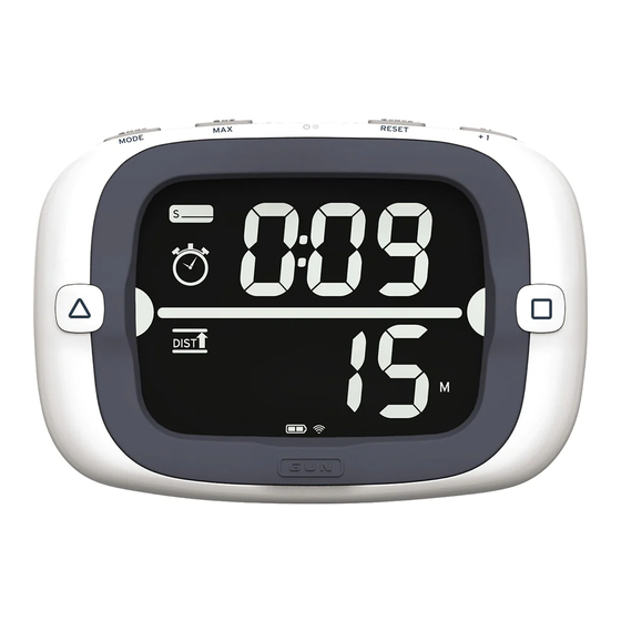
Modes Start Mode Start Mode Timer Indicator Timer Display Line is Set Indicator Line End Distance- Indicator to-line Display Indicator Distance Start mode combines a timer and perpendicular distance to line display to provide the information necessary for a perfect start at the gun. The semi-circles next to the buttons indicate if the respective ends are set. -
Page 13: Race Mode
Modes The early / late bar graph provides a graphical representation for your estimated location at the gun based on your current position, speed, Course Over Ground, and the time remaining in the countdown. The bar graph extends above the illustrated line if the calculated future location is over the line and below the illustrated line if your future location is under the line. -
Page 14: Magnetic Heading
ProStart. The ProStart displays COG only when your speed is greater than 0.5 knots. If your speed is less than 0.5 knots the ProStart will display ‘- - -’ for COG regardless of which direction you are moving. -
Page 15: Heel Angle Bar Graph
When COG is selected as the direction output, the heel angle feature is disabled. Heel angle is also recorded in the ProStart’s data storage. Heel to starboard is shown as positive degrees. Heel to port is shown as negative degrees. -
Page 16: Operation
The operation of the ProStart relies on low-power radio signals from GPS satellites that orbit the earth at an altitude of approximately 20,000 km. As a result, the ProStart must be outdoors with a clear view of the sky to function properly. Stay away from tall buildings and forests when acquiring a signal off the... -
Page 17: Using The Backlight
If your ProStart has a low battery, the backlight will automatically turn off to reduce power consumption and extend the runtime of your ProStart. Show Off Your Maximum Speeds Everyone likes to know how fast you went. The ProStart max speed recall pulls your best speeds up with the click of a button. Hold... -
Page 18: Keep Your Hand On The Tiller
Operation To reset the maximum speeds, press RESET while holding MAX. Keep Your Hand on the Tiller when timer expires when RC, PIN, GUN, RESET, is pressed Modes switch automatically to minimize the need for your input. The mode switches from Start to Race mode when the timer expires. -
Page 19: Set The Start Line
LCD at the respective ends. Pin Set Line Square To Once the start line is set, the ProStart will display a line between the semi-circles to indicate that the line is set. The direction to which the start line is square will flash three times (°... -
Page 20: Use The Timer
Operation Use the Timer +1 min Timer Reset Change the reset time by pressing to scroll through the minutes. The timer can be set to 1:00 ~ 15:00. Start the timer by pressing GUN. RESET Timer Start Timer Timer Counting Down +1 min Add one minute to the timer without stopping the timer by pressing +1. -
Page 21: Configuration
Configuration Configuration The ProStart has four user configurable settings: Magnetic Declination Bow offset Heading / COG Compass damping Configuring your ProStart Adjusting magnetic declination, bow offset, magnetic heading / COG, and damping is done using the line and PIN) buttons. -
Page 22: Setting Compass Declination And Bow Offset
Configuration Setting Compass Declination and Bow Offset Once you have entered user setup by holding RESET for 3 seconds, your first menu is Magnetic Declination. To set the bow offset you must first go through the declination menu then press to get to the bow offset menu as illustrated below: Hold... -
Page 23: Setting Direction Output And Compass Damping
Configuration Setting Direction Output and Compass Damping To select direction output (Heading or COG) you must go through the declination menu and bow offset menu, pressing the button each time to progress to the next menu. To set damping, you must go through the declination, offset menus, and Heading / COG selection pressing the button each time to change menus. -
Page 24: Magnetic Declination
Setting the bow offset is optional. Bow offset is the distance in meters from where the ProStart is mounted to the bow of your boat. In start mode the offset is used to calculate the distance between the tip of your bow and the start line. - Page 25 Configuration The ProStart has three levels of damping 0 (no damping), 1 (low), and 2 (high). The factory default setting is 0 or no damping. To change the damping enter ‘User Setup’, navigate to the damping setting menu and then press the line set buttons to adjust the damping up or down.
-
Page 26: Understanding 'Distance To Line
Understanding ‘Distance to Line’ Once you have set (pinged) both ends of the starting line the ProStart connects these two points in a straight line of infinite length. The ProStart calculates distance to line as its perpendicular distance to the infinite start line. -
Page 27: Setting The Ends
Understanding ‘Distance to Line’ Setting the Ends The start line ends can be set anywhere along the start line. We recommend sighting both the pin and the race committee ends from outside the line. Another method is to get close to the ends just inside the line and set them. -
Page 28: Understanding 'Line Square To
In order for the ‘Line Square To’ output to work with your magnetic compass, you need to have your local magnetic declination entered into the ProStart. See the Configuration section on page 20 for instructions on entering your local magnetic declination into the ProStart. -
Page 29: Data Storage
The ProStart can store up to 1000 hours of data. Download data The ProStart works like a USB thumb drive. Plug your ProStart into a computer to see your tracks organized by date. Go to chartedsails.com to replay and share your tracks. - Page 30 Once the cap is open wipe away any loose water droplets. If you ever see signs that water is leaking inside the enclosure please contact Velocitek Support immediately at (866)-498-6737 or support@velocitek.com to arrange to have your device...
- Page 31 Velocitek assumes no liability for any accident, injury, death, loss, or other claim related to or resulting from the use of this product. In no event shall Velocitek be liable for incidental or consequential damages relating to or resulting from the use of this product or any of its parts.
- Page 32 Contact Contact Mail: Velocitek, Inc. 126 N B Street San Mateo, CA 94401 Fax: +1-650-618-2679 Phone: Calls will be answered 9AM ~ 6PM, US Eastern Time (UTC-4 Summer, UTC-5 Winter) US and Canada: +1-866-498-6737 International: +1-650-592-4519 Email: support@velocitek.com Website: http://www.velocitek.com Support: http://www.velocitek.com/support...
- Page 33 Compliance Compliance FCC Compliance Statement This device complies with Part 15 of the FCC Rules. Operation is subject to the following two conditions: (1) This device may not cause harmful interference, and (2) this device must accept any interference received, including interference that may cause undesired operation. NOTE: This equipment has been tested and found to comply with the limits for a Class B digital device, pursuant to Part 15 of the FCC Rules.
- Page 34 Index Index Acquire a GPS Signal, 15 Line Square To, 27 Backlight, 16 Magnetic Declination, 23 Batteries, 8 Magnetic Heading, 12 Bow Offset, 21, 23 Maintenance, 29 Buttons, 9 Maximum Speeds, 16 Modes, 10 Compass Damping, 22, 23 Compass Declination, 21 Pinging, 25 Compliance, 32 pitch, 28...
Need help?
Do you have a question about the Prostart and is the answer not in the manual?
Questions and answers
how do i enlarge screen to speed only in large display