Table of Contents
Advertisement
Advertisement
Table of Contents

Related Manuals for Velocitek SC-1


Summary of Contents for Velocitek SC-1
- Page 1 SC-1 Reference Manual Firmware Version 2.4F (Full Functionality)
-
Page 2: Table Of Contents
ACTICAL OMPASS VMG M IMER TART ROXIMITY OGGER WHEN YOU GET HOME GPS D OFTWARE NSTALLATION EQUIRED TO OWNLOAD ATA FROM EVICE NSTALLING ONTROL ENTER NSTALLING RIVERS FOR ELOCITEK EVICE SING ONTROL ENTER SC-1 GPS D TORAGE GPS D OWNLOADING... - Page 3 GPS D AVING GPS D LEARING PDATING NFORMATION PDATING EVICE ETTINGS PDATING IRMWARE GPS A AUNCHING CTION EPLAY FROM ONTROL ENTER MAINTENANCE CONTACT INDEX...
-
Page 4: Introduction
SC-1 Features Introduction SC-1 Features The SC-1 is a powerful sail training tool designed to provide you with the feedback you need to sail faster. The SC-1 has the following features: Speed, compass, tactical compass, start line proximity updated at 2 times a second ... -
Page 5: On The Water
Device Overview Displays The following diagram shows the SC-1's two main display areas: The upper and lower displays can both be used to display speed, heading, tactical heading, VMG, start line proximity or timer information. The information shown on each display is made clear by a mode indicator immediately to the left of the numerical display area. -
Page 6: Buttons
Device Overview Buttons The SC-1 is controlled by four different capacitive touch sensors. These touch sensors detect the presence of your thumbs when they are placed on top of the regions shown in the following diagram: The captions on the above diagram indicate how the different touch sensors will be referred to in the... -
Page 7: Battery Life Indicator
Device Overview Battery Life Indicator The battery life indicator is located in the top left corner of the SC-1. As the energy in the device's batteries is consumed, the battery life indicator will undergo the following progression to show you how much run time you have left: When the indicator is fully illuminated you have approximately 20 hours of battery life remaining. -
Page 8: Getting Started
These markings are circled in red on the following photograph: The SC-1 will work with rechargeable nickel metal hydride (NiMH) batteries or standard disposable AA batteries. Disposable batteries will provide approximately 10 hours of life while rechargeable NiMH batteries will last for 20 hours or longer. -
Page 9: Lock Feature
Getting Started Lock Feature The Velocitek SC-1 uses touch sensors to accept user input. Splashing water can trigger the touch sensors. To prevent the device from being inadvertently controlled by splashing water the user can enable lock features. When the device is locked, buttons are non-functional. There are two lock features: ... -
Page 10: Unlocking Procedure
Getting Started Unlocking Procedure Cover the plus button with your thumb. When you hear a beep, move your thumb to the minus button. When you hear another beep, move your thumb back to the plus button. A long beep indicates that you have successfully unlocked the device. -
Page 11: Turning Power On
Getting Started Turning Power On Use the following procedure to turn on the SC-1: Use your thumbs to cover both the Mode and Minus buttons. You will see a countdown starting from 3 on the lower display. If you do not see the countdown appear, remove and reapply your right thumb. -
Page 12: Turning Power Off
Getting Started Turning Power Off When you first insert batteries into the SC-1 it will automatically turn on. To turn it off, use the following procedure: Make sure the buttons are unlocked. Use your thumbs to cover both the Mode and Minus buttons. -
Page 13: Signal Acquisition
The following illustration depicts the GPS signal acquisition process: When the SC-1 is first turned on, both the upper and lower display will show "- - -". The lower display will also blink on and off. -
Page 14: Operating Modes
Operating Modes Operating Modes The Velocitek SC-1 has six different modes: Speedometer Mode Compass Mode Tactical Compass Mode VMG Mode Timer Mode Start Line Mode Any two modes can be displayed simultaneously, one on the upper display and one on the lower displays. -
Page 15: Lower Display Mode Selection
Operating Modes Lower Display Mode Selection Make sure the buttons are unlocked. Put your thumb over the mode button. You will hear a beep and see the mode indicator on the lower display change. Repeat this procedure to cycle through all the modes on the lower display. -
Page 16: Upper Display Mode Selection
Operating Modes Upper Display Mode Selection Make sure the buttons are unlocked. Set the mode on the lower display to be the same as what you want on the upper display. In the case of the illustration, this is VMG mode. Put your thumb over the Up button. -
Page 17: Speedometer Mode
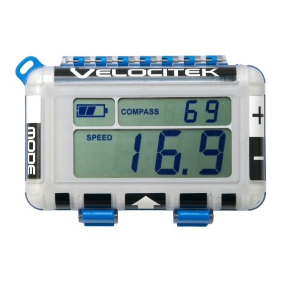
Operating Modes Speedometer Mode In Speedometer mode the display will show your current speed updated at 2Hz (twice a second). The speed can be displayed in knots, miles/hour, kilometers/hour or meter/second by editing the device settings. The following image shows both the upper and lower displays in speedometer mode, showing a speed of 16.9 knots. - Page 18 Operating Modes Resetting Maximum Speeds Use the following procedure to reset the maximum and best 10 second average speeds recorded on the SC-1 to zero: Make sure the buttons are unlocked. Cover both the plus and the minus buttons with your thumb. You will see a countdown from 3 to 0 on the lower display.
-
Page 19: Compass Mode
A major benefit of the SC-1 over a conventional magnetic compass is that it will give you accurate heading information, regardless of the orientation in which it is mounted on your boat. SC-1's compass reading depends only on the direction you are moving, not the direction the device is pointing. - Page 20 On the other hand, low damping will help you to quickly identify the effect of gusts and wind shifts. The damping on the SC-1 can be set to 10 different settings, "d0" “d1” “d2” “d3” “d4” “d5” “d10” “d30” “d60” and "d90".
- Page 21 Operating Modes The procedure for adjusting the damping level on the SC-1 is illustrated below: Make sure the buttons are unlocked. Put the lower display into Compass mode and put your thumb over the Plus button to increase the damping level or over the Minus button to decrease the damping level.
-
Page 22: Tactical Compass Mode
Operating Modes Tactical Compass Mode When the SC-1 is in Tactical Compass mode, it displays your heading relative the wind direction stored on the SC-1. When it is correctly configured, the tactical compass will show you the same numbers at equivalent angles on both tacks. - Page 23 Operating Modes Defining the Wind Direction in Tactical Compass Mode The reference wind direction stored on the SC-1 is used as a basis for calculating heading to wind in tactical compass mode as well as VMG in VMG mode. The wind direction can be defined in tactical compass mode by sailing upwind and tacking several times while making adjustments to the indicated heading to wind until the same number is seen on both tacks.
- Page 24 Operating Modes Guess your heading relative to the wind and adjust the indicated heading to wind on your SC-1 to that value. 45° is a good starting point for many boats. Tack and sail close-hauled on the new tack. Adjust your indicated heading to wind to the same value used in step 3.
- Page 25 Using the Tactical Compass to Identify Wind Shifts The following sequence shows how you would use the SC-1 to identify a lift while sailing upwind on port tack. The boat in the example sails at 40° to the wind when trimmed using telltales.
-
Page 26: Vmg Mode
Operating Modes VMG Mode In VMG Mode the SC-1 shows your Velocity Made Good based on a wind direction you have defined. The display is updated at 2Hz (twice a second). The SC-1 calculates your VMG upwind and downwind using the method illustrated below: Whether you are sailing upwind or downwind, the SC-1 breaks your boat's velocity into two perpendicular components. - Page 27 Operating Modes Defining the Wind Direction in VMG Mode Use the following procedure to program in the direction of the wind so that the SC-1 can calculate your VMG: Set the upper display to Compass mode and the lower display to VMG mode. Bear-off to a dead run so you are moving straight downwind.
- Page 28 Please Note: Increasing the display damping before beginning this procedure will help you get a steady reading on the upper display. Tuning the Programmed Wind Direction in VMG Mode Use the following guidelines to adjust the wind direction programmed on the SC-1 when you are sailing upwind: ...
-
Page 29: Timer Mode
0:03, 0:02, 0:01, 0:00, 4:59, 4:58... If the rollover is disabled the countdown will reset to 5:00 at 0:00. The following diagram shows the SC-1 with both the upper and lower displays in timer mode indicating one minute and 36 seconds remaining before the start. Note that there is no mode indicator for timer mode on the upper display. - Page 30 Operating Modes Starting the Timer Use the following procedure to start the countdown: Make sure the buttons are unlocked. Put your thumb over the minus button. The device will beep and the countdown will begin. If the lock feature is enabled the buttons will lock immediately.
- Page 31 Operating Modes Resetting the Timer Make sure the buttons are unlocked. Put your thumb over the plus button. Hold the plus button for 2 seconds. You will hear a long beep and the timer will reset to the highest sync point you set up in device settings.
- Page 32 Operating Modes Synchronizing the Timer Use the following procedure to synchronize the timer in response to a signal from the race committee: Make sure the buttons are unlocked. Put your thumb over the minus button. The timer will jump down to the next lowest sync point you have set in device settings. The timer will continue counting normally and the buttons will be automatically locked.
- Page 33 Operating Modes Incrementing Minutes The timer minutes can be incremented without affecting the timer seconds. Make sure the buttons are unlocked. Put your thumb over the plus button. The timer will jump up a minute.
-
Page 34: Start Line Proximity Mode
SC-1 is actually mounted can be set in the device settings. The device settings also allow you... - Page 35 When you are more than 1000 meters (or boat lengths) away from the start line the display will switch to displaying "FAr". The following diagram shows the SC-1 with both the top and bottom displays in Start Line Mode indicating that the tip of your bow is 26 meters (or boat lengths) behind the start line.
- Page 36 Operating Modes Setting Committee Boat End Use the following procedure to set the committee boat reference point: Unlock the buttons Press the Minus button Hold for 3, 2, 1 Release on 0 The device will beep and "-C-" will be displayed to confirm that you have set the committee boat reference point.
- Page 37 Operating Modes Setting Pin End Use the following procedure to set the pin reference point: Make sure the buttons are unlocked. Press the Minus button Hold for 3, 2, 1 Release on 0 The device will beep and "-P-" will be displayed to confirm that you have set the pin reference point.
-
Page 38: Data Logger Mode
Data Logger Mode By turning off all modes, you can use the SC-1 strictly as a data logger. In this mode, the device displays "OFF" in the lower display at all times. This mode allows you to log GPS tracks during races while... -
Page 39: When You Get Home
Software Installation Required to Download GPS Data from Your Device When You Get Home This section describes how to install Control Center, change device settings on the SC-1 and download GPS data from the SC-1. Software Installation Required to Download GPS Data from Your Device The following items will be installed on your PC by the Velocitek installer: ... - Page 40 Installing Control Center Click Next.
- Page 41 Installing Control Center Once the setup is complete you will get the following message. Click Finish.
- Page 42 Installing Control Center The rest of the installation will be guided by the Install Shield Wizard. If you do not have Java 2 or .Net Framework 3.0, the wizard will proceed to install them. Click Install. Otherwise the wizard will proceed with installing Control Center.
- Page 43 Installing Control Center Select I accept, click Next.
- Page 44 Installing Control Center Select Typical, click Next.
- Page 45 Installing Control Center Once Java installation is complete you will get the following message. Click Finish. If you get the following message, do not restart computer to proceed with rest of the installation. Click No.
- Page 46 Installing Control Center 10 The wizard will continue with the installation of .Net Framework 3.0.
- Page 47 Installing Control Center 11 Once .Net Framework 3.0 is installed, the wizard will proceed with the installation of Control Center. Click Next.
- Page 48 Installing Control Center 12 Enter User Name and Company Name. Click Next.
- Page 49 Installing Control Center 13 Select Typical, click Next.
- Page 50 Installing Control Center 14 Click Next. 15 Click Continue Anyway.
- Page 51 Installing Control Center 16 Once Control Center is finished installing you will get the following message. Click Finish.
- Page 52 Installing Control Center 17 If prompted, restart your computer. Select Yes, click Next.
-
Page 53: Installing Drivers For Your Velocitek Device
Control Center to communicate with your GPS device through a USB link. Use the following procedure to install the drivers for your Velocitek GPS device: Open your device's waterproof case and connect your GPS device to your computer using the included USB cable. - Page 54 Installing Drivers for Your Velocitek Device Once the device has been connected to your PC, the following window will appear. Select the No, not this time option and click on Next.
- Page 55 Installing Drivers for Your Velocitek Device Select Install the software automatically and click on Next. 4 Select Continue Anyway.
- Page 56 Click Finish and you will be taken back to a screen that looks like what you saw in step 3. Repeat steps 3 through 5 to complete the driver installation. Congratulations! You are now ready to start downloading GPS data from your Velocitek device.
-
Page 57: Using Control Center
Time The SC-1 has room for 17, 35 or 70 hours worth of GPS trackpoints at recording rates of 1Hz (once every second), 1/2Hz (once every 2 seconds), and 1/4Hz (once every 4 seconds) respectively. When the SC1's memory becomes full, the oldest trackpoints on the device are automatically deleted to free up space for... -
Page 58: Downloading Gps Data
Using Control Center Downloading GPS Data Use the following procedure to download GPS data from your SC-1: Run Control Center. Connect your SC-1 to your PC with the included cable... - Page 59 Using Control Center Your GPS tracks are automatically broken up into segments whenever The SC-1 is turned off and on again USB cable is disconnected The start and end dates and times for each track segment are shown in the track segment window using the system time zone of the PC.
- Page 60 Using Control Center Click on the Download button to begin transferring the GPS data from your SC-1 to your computer. This process can take as long as 30 seconds for every hour of GPS data stored on the device. If the...
- Page 61 Using Control Center Once the data transfer is complete, you will see an automatically generated file name appear at the bottom of the Control Center window. In the example shown this file name is 080508_083450. The file names are automatically generated. The file names are created with the following format: yearmonthday_hourminutesecond.
- Page 62 .kml, this is the format used by Google Earth. The .kml format contains only a list of positions. .vcc, this is Velocitek's proprietary format. It can only be viewed in a text editor such as Notepad. The .vcc file format contains a list of times, positions, speeds, and headings. The speeds and headings in a .vcc file were determined in real time directly from measurements of...
- Page 63 Using Control Center Saving GPS Data as a .vcc File Download the GPS data you want the file to contain. Select File->Save...
- Page 64 Using Control Center Give the file a different name from the automatically generated one if you wish. Click on the Save button to complete the process.
- Page 65 Using Control Center Saving GPS Data as a .kml or .gpx File Download the GPS data you want the file to contain. Select File->Export and then choose the format you want. In the screenshot, the .kml format was selected.
- Page 66 Using Control Center Name the file and click on the Save button to complete the process.
- Page 67 Using Control Center Converting a .vcc File into a .gpx or .kml File Select File->Open and then choose the .vcc file you want to convert.
- Page 68 Using Control Center Select File->Export and then choose the format you want to convert it to.
- Page 69 Using Control Center Change the name of the converted file (optional) and click the Save button to complete the process.
- Page 70 SC-1 will contain a record of your last several days of sailing. Since old data is automatically deleted, you may never need to clear GPS data from the SC-1's memory. If for any reason you do want to delete GPS data, select Setup->Erase All Track Segments.
-
Page 71: U Pdating U Ser I Nformation
Using Control Center Updating User Information You can store information about yourself and your boat in the SC-1. The information will be displayed in Control Center when your device is connected to a computer. It will also be attached to .vcc files created with data from your device. - Page 72 0 for compass declination. Default compass declination is 0 degrees. When using a magnetic compass in conjunction with the SC-1, setting the compass declination to the local declination is useful since both instruments will be referenced to magnetic north.
- Page 73 Using Control Center Logging Rate Logging rate is the rate at which the SC1 records data. User can select from 1Hz (once every second), 1/2Hz (once every 2 seconds), and 1/4Hz (once every 4 seconds). The default logging rate is 1/2Hz Speed Display In Speed can be displayed in 4 different units of measurement, knots, miles/hour, kilometers/hour and meters/second.
- Page 74 Default boat length is 1 meter. Device Offset from Bow Device offset from bow is the distance in meters from where the SC-1 is mounted to the bow of your boat. In start line mode the offset is used to calculate the distance between the tip of your bow and the start line.
-
Page 75: U Pdating F Irmware
Firmware is the miniature computer program that runs on the GPS device's microprocessor to control how it operates. From time to time Velocitek releases new versions of its GPS device firmware. These updates are designed to either improve your device's performance or to tailor its functionality towards a specialized application. - Page 76 Using Control Center Choose the firmware .hex file you want to install and click Open. Wait for the firmware file to be uploaded to your GPS device. This will take approximately 10 minutes. Progress will be indicated by a horizontal bar graph at the bottom of the Control Center window.
-
Page 77: L Aunching Gps A Ction R Eplay From C Ontrol C Enter
Using Control Center Launching GPS Action Replay from Control Center Download GPS data or open *.vcc files in Control Center. Click Play with GPS Action Replay. -
Page 78: Maintenance
To ensure your SC-1's enclosure remains watertight and the electronics are not destroyed by corrosion, please take the following precautions: Store your SC-1 with the latches undone and the enclosure partially open. This leaves the gasket decompressed and allows it to expand. This ensures that it will fit tightly when the enclosure is latched and fully closed. -
Page 79: Contact
Contact Contact Mail: Velocitek, LLC 271 B Kahiko St. Paia, HI 96779 Fax: +1-650-618-2679 Phone: Calls will be answered 9AM ~ 6PM, Hawaiian Standard Time (GMT-10) US and Canada: +1-800-693-1610 International: +1-650-362-0499 Email: support@velocitek.com Website: http://www.velocitek.com Forum: http://www.velocitek.com/forums/ Support: http://www.velocitek.com/support... -
Page 80: Index
Index Index Modes Enable ..............70 Battery Life ................4 Beep Enabled ..............70 Operating Modes .............. 11 Boat Length ..............71 Buttons ................3 Recalling Maximum Speeds ..........14 Resetting Maximum Speeds ..........15 Clearing GPS Data .............. 67 Compass Declination ............ - Page 81 Index Wind Direction in Tactical Compass Mode ......20 Wind Direction in VMG Mode ........... 24...
Need help?
Do you have a question about the SC-1 and is the answer not in the manual?
Questions and answers