
Related Manuals for Acroprint ATR360


Summary of Contents for Acroprint ATR360
- Page 1 ATR360 Top Loading Time Recorder With Fingerprint & Proximity Badge User Verification User Manual...
- Page 2 Lithium Battery Caution: The circuit board on this terminal is populated with a lithium battery to protect data or programs stored in the Random Access Memory (RAM). Do not, under any circumstances, attempt to replace the lithium battery in the terminal. Failure to comply may void your warranty.
-
Page 3: Table Of Contents
Table of Contents Before You Start! ......................1 What’s In the Box........................1 Time Recorder Mode Settings ....................2 Clock Overview ......................3 Top View ..........................3 Front View..........................3 Rear View ..........................4 Initial Setup........................5 Setting Year ..........................5 Setting Month/Date ........................5 Setting Time..........................5 Setting Day Advance Time.......................5 Setting Pay Period ........................5 Setting Clock Display Format ....................5... - Page 4 Maintenance ........................ 22 Replacing the Ribbon Cassette .....................22 Replacing the Circuit Board Batteries ..................23 Installing the Operational Battery Pack..................24 Cleaning the ATR360 ......................25 Cleaning the Fingerprint Sensor ....................25 Appendix........................26 Connecting External Signal Devices (Bells & Horns).............26 Wall Mounting Instructions.....................27 Fingerprint Privacy .........................27...
-
Page 5: Before You Start
Acroprint Customer Service at (800) 334-7190. 2) Connect the ATR360 power adapter and plug it into a wall outlet to turn the clock on. If this is the first time you’ve turned the clock on, open the Ribbon Access Door with the key and, using a ball point pen, press the Reset button. -
Page 6: Time Recorder Mode Settings
Time Recorder Mode Settings Default Mode Setting Values Value Year 2000 – 2099 Year of Mfg Date 1-12 Mo, 1-31 Date 01, 01 Time 1-23 Hr, 0-59 Min 12 : 00 End of Day Change Time 1-23 Hr, 0-59 Min 00 : 00 Set Card Format 00: first row blank... -
Page 7: Clock Overview
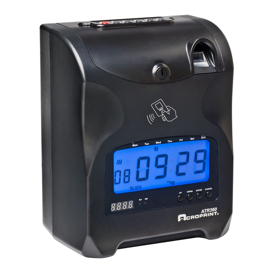
Clock Overview Top View Front View Battery Status Indicator: A fully charged Battery will have (5) bars. DST Icon: displays when exiting programming mode when DST is turned on. Each blink of the colon is one sec. -
Page 8: Rear View
Rear View... -
Page 9: Initial Setup
Initial Setup Setting Year 1. Remove top cover a. Locate buttons at the top of the clock labeled P4, P5 and P6 i. P4 changes values down ii. P5 changes values up iii. P6 is used to save and select modes 2. -
Page 10: Setting Start And End Of Dst
Setting Start and End of DST 27. The mode indicator “08” will be flashing, press P5 to switch to mode “09” 28. The mode indicator “09” will be flashing, press P6 to select 29. Press P4 or P5 to select the correct month (US-March) 30. -
Page 11: Fingerprint Settings Table
Fingerprint Settings Table A list of the fingerprint settings is shown below: Setting Description Add.U Add User: Add Fingerprint and/or Proximity badge users to the clock. Change/delete existing Fingerprint templates or Proximity badge numbers. dEL.U Delete Users: Remove a user or remove Fingerprint templates and/or Proximity badges from the clock. -
Page 12: Correct Finger Positioning On The Sensor
Correct Finger Positioning on the Sensor Place finger flat on the sensor surface Place finger in the center of the sensor surface Incorrect Finger Positioning: Tips for Improving the Success of Fingerprint Reads Finger Print Setup 1. Remove top cover 2. -
Page 13: Add User
Add User 5. Press enter a. Users must be assigned a number user number. You may add up to 150 users and 5 administrators 6. To assign the user a number use the up and down buttons to change each digit. Start with first digit. -
Page 14: Important! Setting The Real-Time Clock (Rtc)
Any time you change the system clock you must also synchronize the RTC! The ATR360 can maintain accuracy to within ±3 sec/wk of the RTC. It is recommended that you synchronize the RTC with the system time (clock display) at least once a year. -
Page 15: Editing Shift Intervals
Editing Shift Intervals 1. Open clock lid. Press "FP Setup" button 2. Press "down" until the LED display shows "InO.S". Press "Enter". "PE.1” will be displayed. Press "up/down" if you want to edit a different shift. Press "Enter" to select the shift to edit. Edit the Start of Shift time (hrs : min). Press and hold "Enter"... -
Page 16: Set Ink Color Change Time
Set Ink Color Change Time Remove top cover Locate the program switch to the left of the finger print reader. Move the switch to the down position, you are now in setup mode Press P1. P1,P4,P5,P6 will now be flashing If this is the initial setup you must begin with 01 Press P6 to save Press P4 or P5 to select the correct hour... -
Page 17: Set Column Change Time Setup
Set Column Change Time Setup Remove top cover Locate the program switch to the left of the finger print reader. Move the switch to the down position, you are now in setup mode Press P3 P3, P4, P5, P6 will now be flashing If this is the initial setup you must begin with 01 Press P6 to save Press P4 or P5 to select the correct hour for the first time slot... -
Page 18: Using The Time Clock
Using the Time Clock Using the Time Card to Clock In 1. When clocking in P1, P3 or P5 must be selected 2. Insert the time card with the current week facing you and the card in the upright position 3. -
Page 19: Features And Specifications
Features and Specifications Clock Features User Authentication Method Fingerprint or Proximity Badge Display Language English Operation Mode Stand-alone (No PC Interface) Proximity Card Reader Operational Battery Backup Optional Auto Card Feeder Printing Method 9-Pin Dot Matrix Eliminates Buddy Punching Two Color Printing Perpetual Calendar Auto Fix Positioning Power Failure Printing... -
Page 20: Miscellaneous
The optional Operational Battery Pack (58-0114-000) is a 12 cell NiMH (Nickel Metal Hydride) battery pack that recharges when the ATR360 is plugged in. In the event of a power failure the clock will instantly switch to battery power without any interruption in service. The operational battery pack allows for full operation of the clock with punching using the fingerprint reader or Prox badge. - Page 21 Note: Actual battery life depends on many factors such as battery age, temperature, discharge history, etc., and can vary greatly depending on these factors. The ATR360 should be plugged in for 12 hours to fully charge the battery pack. For more information see “Installing the Operational Battery Pack” in the Appendix.
-
Page 22: Fingerprint Reading Issues
Clean the fingerprint sensor (see cleaning the fingerprints fingerprint sensor. Using a fingerprint overlay on the sensor will often significantly improve fingerprint reads (call Acroprint for availability). Clock has trouble reading Move clock out of direct or bright sunlight. fingerprints on sunny days... -
Page 23: Troubleshooting
Flip card over and re-insert Clock beeps (monthly card) and rejects time card Use card approved for the Incompatible time card ATR360 Ribbon cassette not properly Remove and re-insert ribbon seated cassette correctly Print too light The print ribbon is dried out... - Page 24 Replace the coin cell on the losing time motherboard needs to be replaced motherboard Display Off, Clock has Defective Motherboard Contact Local Dealer or Acroprint Power for repair. Defective LCD Display Display is in AM/PM The clock display format and print...
-
Page 25: Frequently Asked Questions
5. Q: Why is the light for the fingerprint reader not working? A: Make sure the fingerprint switch is set to “FP ON”. If this doesn’t correct the problem contact your local dealer or Acroprint for repair. Q: Can I turn the fingerprint reader off and just use prox badges? A: No. -
Page 26: Maintenance
15. Q: I can’t get my clock to print for any employees. It just keeps giving an “err” message. A: Make sure the display time is synchronized to the RTC time. For more info on troubleshooting or general “how to” info go to: http://support.acroprint.com Maintenance Replacing the Ribbon Cassette 1. -
Page 27: Replacing The Circuit Board Batteries
Replacing the Circuit Board Batteries The ATR360 is equipped with (2) CR2032 3v Lithium Coin Cell batteries: one battery is on the Main board and the other is on the Display board. The batteries should last approximately 1.5 to 2 years under normal operating conditions. Do not attempt to replace these batteries as it will void your warranty. -
Page 28: Installing The Operational Battery Pack
If the door won’t close check to make sure the wires aren’t under the battery. Plug in the power supply once the battery door is secure. The ATR360 should be plugged in for 12 hours to fully charge the battery pack. -
Page 29: Cleaning The Atr360
Cleaning the ATR360 Do not use cleaning products that contain alcohol or other strong chemicals as they could discolor or crack the terminal housing. Use a soft damp cloth to remove dirt. Wipe dry. Cleaning the Fingerprint Sensor Caution: Do not use any cleaners on the sensor or it could be damaged. -
Page 30: Appendix
Gently pull on the wires to make sure they are firmly secured in the terminal block. In order to use a bell or horn a relay is required. Please call Acroprint or your Dealer to order the relay (PN 01-0230-000). -
Page 31: Wall Mounting Instructions
Wall Mounting Instructions The ATR360 can be placed on a table or desk and it can also be mounted to a wall. A mounting template is included with the documents for the ATR360. If you misplace the template you can download it at: http://support.acroprint.com... -
Page 32: Supplies, Parts & Accessories
4-1/4" Bell, 120vAC 50/60Hz 64-0105-000 8” Bell, 120vAC 50/60Hz 75-0185-000 US Power Plug (for 56-0135-000) 75-0185-001 Euro Power Plug (for 56-0135-000) 75-0185-002 UK Power Plug (for 56-0135-000) An updated list of accessories with pricing can be found on the web at: www.acroprint.com... - Page 33 For your reference, fill out the information below and keep it in a safe place. Model Number _______________________________________________ Serial Number ________________________________________________ Date Purchased ______________________________________________ Purchased From ______________________________________________ Location ____________________________________________________ Telephone Number ____________________________________________...
- Page 34 06-0400-000 Rev. H...
Need help?
Do you have a question about the ATR360 and is the answer not in the manual?
Questions and answers