
Related Manuals for Baroness LM531


Summary of Contents for Baroness LM531
- Page 1 5-Unit Reel Mower Owner's Operating Manual Serial No. LM531:10041- "Required reading" Read this manual before using the machine. Original Instructions Ver.1.6...
- Page 2 LM531 Regulations California Proposition 65 California Spark Arrester (For California, USA) (For California, USA) Warning WARNING: Operation of this equipment may create Operating, servicing and maintaining sparks that can start fires around dry a passenger vehicle or off-road vegetation. vehicle can expose you to chemicals A spark arrester may be required.
- Page 3 LM531 Greeting Thank you for purchasing the Baroness product. QR Code This manual describes the proper handling, adjustment, and inspection of your product. A QR code label is affixed on the machine. We hope you will use the product safely, and take advantage of its best performance.
- Page 4 The operator is responsible for operating the product properly and safely. Maintenance service for this machine should be performed by a mechanic with expertise. If you have any questions concerning maintenance or genuine parts, please contact a Baroness dealer or Kyoeisha.
- Page 5 When replacing parts, be sure to use genuine Baroness parts or parts designated by Kyoeisha. Note that the Baroness product warranty may not apply to defects caused by the use of parts from other companies. Prior to use, carefully read the following manuals to thoroughly understand the contents for safe and correct operation.
- Page 6 LM531 Introduction...
-
Page 7: Table Of Contents
LM531 Contents Safety .............. Page 1-1 Lubrication ............. Page 6-6 Adjustment and Replacement ......Page 6-8 Safe Operating Practices .......Page 1-2 Storage ............Page 6-18 Disposal ............Page 2-1 Repair ..............Page 7-1 Recycle and Waste Disposal ......Page 2-2 Precautions for Repair ........Page 7-2 Product Overview .......... - Page 8 LM531 Contents...
-
Page 9: Safety
LM531 Safety Safe Operating Practices ...... Page 1-2 Training ..........Page 1-2 Preparation ..........Page 1-2 Operation ..........Page 1-3 Maintenance .......... Page 1-4 Storage ..........Page 1-5 Page 1-1... -
Page 10: Safe Operating Practices
LM531 Safety Failure to adequately follow these safety Never allow children or people unfamiliar precautions may cause an accident resulting in with these instructions to use or service the injury or death. machine. Local regulations may restrict the age of the... -
Page 11: Operation
LM531 Safety Add fuel before starting the engine. Never operate while people, especially Never remove the cap of the fuel tank or children, or pets are nearby. add fuel while the engine is running or Only operate in good light, keeping away when the engine is hot. -
Page 12: Maintenance
LM531 Safety Before removing the grass catcher. Allow the engine/muffler to cool before checking/maintenance. Before making height or depth adjustment unless adjustment can be made from the To reduce the fire hazard, keep hot parts operator's position. such as the engine and silencer/muffler, battery compartment and fuel storage area Before clearing blockages. -
Page 13: Storage
LM531 Safety When checking the hydraulic circuit for Swallowing engine coolant can cause injury pinhole leaks or oil leakage from nozzles, do or death; keep out of reach from children and not use your hands. pets. Use items such as paper or corrugated cardboard to find leakage points. - Page 14 LM531 Safety Page 1-6 Safe Operating Practices...
-
Page 15: Disposal
LM531 Disposal Recycle and Waste Disposal ....Page 2-2 About Recycle ........Page 2-2 About Waste Disposal ......Page 2-2 Page 2-1... -
Page 16: Recycle And Waste Disposal
LM531 Disposal Recycle and Waste Disposal About Recycle Recycling battery etc. is recommended for environmental conservation and economical use of resources. It may be required by local laws. About Waste Disposal Make sure that waste generated when servicing or repairing the machine is disposed of in accordance with local regulations. -
Page 17: Product Overview
LM531 Product Overview Specifications ........Page 3-2 Specifications .........Page 3-2 Mower Units ...........Page 3-3 Sound Pressure Level ......Page 3-3 Sound Power Level ....... Page 3-3 Vibration Level ........Page 3-3 Carbon Dioxide (CO2) Emissions ..Page 3-3 Names of Each Section ......Page 3-4 Regulation Decals ........Page 3-5... -
Page 18: Specifications
LM531 Product Overview Specifications Specifications Model LM531 Name 5-Unit Reel Mower Mower unit type 22 in Total length 303 cm 119.29 in During 296 cm 116.54 in operation Total width Dimensions During 220 cm 86.61 in transport ROPS 196 cm 77.17 in... -
Page 19: Mower Units
LM531 Product Overview The factory default maximum engine rpm is 3,100 rpm. Mower Units Baroness mower unit that can fit this machine is the model marked with a circle in the "Attachable unit" column. LM531 Baroness mower unit Model Attachable unit... -
Page 20: Names Of Each Section
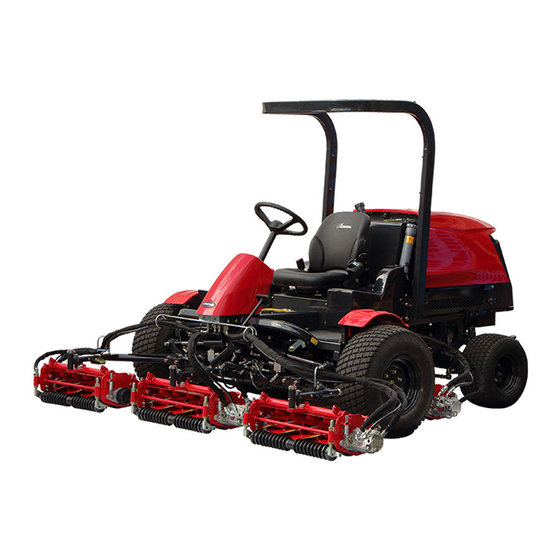
LM531 Product Overview Names of Each Section Steering wheel Seat Throttle lever Mower unit up/down lever Reel rotation switch Light switch Stop valve Mower lock lever (Latch) Reel reverse switch Reel rotation/stop switching lever Traveling pedal Brake pedal Parking brake lock lever... -
Page 21: Regulation Decals
LM531 Product Overview Description of Regulation Decals Regulation Decals Serial Number Plate Positions of Regulation Decals The serial number plate indicates the model and serial number of the machine. 4ogipb-001 Serial Number Plate_001 Specification Decal H,I,J (For EU/UK) The Specification decal indicates the model and weight, etc. - Page 22 LM531 Product Overview Noise Emission Decal ROPS Compliance Decal (For EU/UK) The ROPS compliance decal indicates the The noise emission decal indicates the sound manufacturer, model, etc., in accordance with power level determined by measuring International Standard ISO 21299:2009. identical machines in accordance with the procedure specified in the regulations of EU or UK.
- Page 23 LM531 Product Overview Recycle Decal Indicating Diesel Fuel Decal Recycle Decal illustrates Recycle Mark in (for USA) accordance with local regulation. It indicates the fuel to be used. (For Europe) Use low sulfur or ultra-low sulfur diesel fuel (sulfur-free diesel fuel).
- Page 24 LM531 Product Overview Spark Arrester Warning Decal (For the State of California, USA) Spark arrester warning decal describes the warning messages as required by California Public Resources Code. bfaymx-001 Spark Arrester Warning Decal_001 Page 3-8 Regulation Decals...
-
Page 25: Safety Signs And Instruction Signs
Positions of Safety Decals and Instruction Decals_002 Part numbers for decals that need to be replaced are listed in the parts catalog. Order them from a Baroness dealer or Kyoeisha. Positions of Safety Decals and Instruction Decals quwxcl-214... - Page 26 LM531 Product Overview Decal for operation 2 Hydraulic oil icon Diesel fuel icon Fire prohibited decal Decal on reading owner's operating manual (#10001-10075) Caution to rotating object decal Caution to hot parts decal Caution for spouting coolant decal DO NOT STEP caution decal...
-
Page 27: Description Of Safety Decals And Instruction Decals
LM531 Product Overview Description of Safety Decals and Instruction Decals Caution Rollover - Do not work on slopes of 15 Decal for Operation 2 degrees or more. Decal for operation 2 When you descend a slope, lower the mower LM2400-0918Z0 units and then drive at low speed. - Page 28 LM531 Product Overview Hydraulic Oil Icon Fire Prohibited Decal K4209000980 K4205001940 Hydraulic oil icon Decal, fire prohibited Read the Owner's Operating Manual. Warning Keep away from fire. i77xz6-001 Hydraulic Oil Icon_001 Diesel Fuel Icon r653fo-001 K4209001000 Fire Prohibited Decal_001 Diesel fuel icon Decal on Reading Owner's Operating Manual Use diesel fuel.
- Page 29 LM531 Product Overview Caution to Rotating Object Decal Caution for Spouting Coolant Decal K4205001530 K4205001970 Decal, caution to rotating object Decal, caution for spouting coolant Warning Caution Watch for rotating parts - Keep your hands Caution for spouting coolant - Do not open away from the belts while the engine is while hot.
- Page 30 LM531 Product Overview Caution for Mower Lock Decal K4205001900 Decal, caution for mower lock Lock the mower units when traveling or storing with the mower units #4 and 5 raised. K 4 2 0 5 0 0 1 9 0 0...
-
Page 31: Operation Decals
LM531 Product Overview Operation Decals Positions of Operation Decals 6n6oux-193 Positions of Operation Decals_004 O F F 6n6oux-192 Positions of Operation Decals_005 6n6oux-089 Positions of Operation Decals_001 6n6oux-194 Positions of Operation Decals_006 Mower unit up/down decal Key switch decal Reel rotation mark... -
Page 32: Description Of Operation Decals
LM531 Product Overview Description of Operation Decals Reel Rotation Mark Mower Unit Up/Down Decal Reel rotation mark It illustrates Rotation/Stop of the reel cutter Decal, mower unit up/down (cutting cylinder). This indicates the Up/Down positions of the mower unit. 6ntnq3-001... - Page 33 LM531 Product Overview Traveling/Working Selector Mark Stop Valve Operation Decal Traveling/working selector mark K4203001290 It illustrates the positions where mower units Stop valve operation decal #4 and #5 stop when they are raised. It illustrates Stop/Open of the stop valve.
- Page 34 LM531 Product Overview Brake Mark BACKWARD Decal K4209001200 K4203001440 DECAL, BRAKE Decal, BACKWARD It illustrates the locking position for the This indicates backward travel. parking brake. BACKWARD kqca3e-002 7elqr2-002 BACKWARD Decal_001 Brake Mark_001 Lapping Switch Decal BRAKE Decal K4203001580 K4203001450...
- Page 35 LM531 Product Overview Reel Rotation Decal K4203001300 Decal, reel rotation This indicates rotation of the reel cutter (cutting cylinder). if834g-001 Reel Rotation Decal_001 Reel Stop Decal K4203001310 Decal, reel stop This indicates stop of the reel cutter (cutting cylinder). if834g-002...
- Page 36 LM531 Product Overview Page 3-20 Operation Decals...
-
Page 37: Description Of Functions
LM531 Description of Functions Light Switch ........... Page 4-2 Throttle Lever .........Page 4-2 Mower Unit Up/Down Lever ....Page 4-3 Stop Valve ..........Page 4-3 Mower Lock Lever (Latch) ....Page 4-4 Reel Rotation Switch ......Page 4-4 Slight Lift Function ......... Page 4-4 Reel Reverse Switch ......Page 4-5... -
Page 38: Light Switch
LM531 Description of Functions Light Switch Throttle Lever The throttle lever is located in the operation Caution panel and enables you to adjust the engine rpm. Move the throttle lever toward the "High speed" The lights provide auxiliary lighting. position to increase the engine rpm, and toward Do not travel or operate the machine at night the "Low speed"... -
Page 39: Mower Unit Up/Down Lever
LM531 Description of Functions Note: Mower Unit Up/Down Lever Even if the reel rotation switch is set to the "Rotate" position, the reel cutter (cutting Caution cylinder) stops rotating when the mower unit up/ down lever is moved to the neutral position or Before raising or lowering the mower units, the mower units are raised. -
Page 40: Mower Lock Lever (Latch)
LM531 Description of Functions Mower Lock Lever (Latch) Reel rotation switch Rotate The mower lock levers (latches) are located in Stop the foot area on the left and right sides and are Slight Lift Function used when traveling or storing the machine with mower units #4 and #5 raised. -
Page 41: Reel Reverse Switch
LM531 Description of Functions Reel Reverse Switch Reel Rotation/Stop Switching Lever Important Caution Do not switch the reel reverse switch to the Before operating the reel rotation/stop "ON" or "OFF" position while the reel cutter switching lever, be sure to shift the reel (cutting cylinder) is rotating. -
Page 42: Pedal Stopper
LM531 Description of Functions Parking Brake Lock Lever Traveling pedal Forward Caution Backward Pedal Stopper Never park the machine on a slope. The pedal stopper is located in the right foot Important area. This lever changes the amount that the forward Be sure to release the parking brake before pedal can be depressed. -
Page 43: Usb Socket
LM531 Description of Functions USB Socket Instruments on the Operation Panel Important Do not use the USB socket in rainy weather to avoid malfunction of devices. Use the USB socket to charge or power USB devices such as a smartphone. -
Page 44: Water Temperature Gauge
LM531 Description of Functions Water Temperature Gauge Pilot Lamps This instrument indicates the water Charge Lamp temperature inside the engine. The charge lamp is the left pilot lamp located If the water temperature gauge indicates a in the operation panel. -
Page 45: Safety Mechanisms
LM531 Description of Functions Thermo-start lamp 1/100 wheel Hour wheel Oil Pressure Lamp Safety Mechanisms The oil pressure lamp is the right pilot lamp located in the operation panel. This machine features a safety device for It turns on when the ignition key is set to the starting/stopping the engine. -
Page 46: Warning Mechanisms
LM531 Description of Functions Warning Mechanisms Warning Buzzer Caution When the buzzer (intermittent tone) sounds, be sure to stop operation since the engine is overheated. Do not stop the engine without idling. Allow the engine to cool down, first. Keep the engine idling for about 5 minutes before stopping. -
Page 47: Handling Instructions
LM531 Handling Instructions Operations Before Service ....Page 5-2 Traveling Procedure ......Page 5-19 Cutting Work ........Page 5-20 Opening and Closing of Hood ....Page 5-2 Opening and Closing of Underseat Cutting Operation ........ Page 5-20 Cover ............. Page 5-2 Removal/Installation of Grass Inspection and Cleaning ....... -
Page 48: Operations Before Service
LM531 Handling Instructions Opening and Closing of Underseat Cover Operations Before Service The following sections describe the preparatory Caution works required before performing the services Be careful not to pinch your fingers when you including inspection, adjustment, cleaning. open or close the underseat cover. -
Page 49: Inspection And Cleaning
LM531 Handling Instructions Install two bolts on the rear of the seat. Pull the radiator cover to the back to open Inspection and Cleaning Inspect and clean the machine with the goals of the followings. Accident prevention ・ Failure prevention ・... -
Page 50: Coolant
LM531 Handling Instructions Loosen the knobs on the left and right of Reserve tank the oil cooler, and then tilt the oil cooler. Full Coolant Supply Caution Do not touch the radiator or coolant during engine operation or right after the engine has been turned off. -
Page 51: Oil Cooler
LM531 Handling Instructions Important Do not use solid objects, such as a spatula or screwdriver, or high-pressure water to clean the radiator or oil cooler. Otherwise, special fins or tubes may be damaged, possibly resulting in reduced cooling performance or coolant leakage. -
Page 52: Hydraulic Oil
LM531 Handling Instructions Hydraulic Oil Specified Hydraulic Oil Shell Tellus S2M46 ISO Viscosity Grade ISO VG46 Inspection of Hydraulic Oil 0.873 g/cm Density 15 °C (59 °F) The oil gauge is on the side of the hydraulic (0.0315 lb/in tank. -
Page 53: Hydraulic Hoses
LM531 Handling Instructions Close the center cover and fasten with Air Cleaner the catch clip. Inspection of Air Cleaner Start the engine, raise and lower the mower units, and turn the steering wheel left and For details on handling the engine, please right. -
Page 54: Battery
LM531 Handling Instructions Replace the air cleaner cap, and then fix it Battery inspection items are described below. securely with the clips. Inspecting the exterior Visually inspect the exterior of the battery, and check that there are no cracks, splits,... - Page 55 LM531 Handling Instructions Inspecting the electrolyte level and refilling Danger Danger Warning When you supply battery fluid, wear protective Do not allow the battery fluid level to become garments and safety glasses, etc. lower than the LOWER LEVEL (minimum fluid level line).
-
Page 56: Electrical Wiring
LM531 Handling Instructions Electrical Wiring Inspection of Parking Brake Inspection of Electrical Wiring Make sure that the parking brake is applied after depressing the brake pedal and moving the parking brake lock lever Important forward. Electrical short circuit will cause fire, electrical leakage and malfunction of electrical equipments. -
Page 57: Wire
LM531 Handling Instructions Wire Engine Oil Inspection of Wire Inspection of Engine Oil Make sure that the wire is not cracked or For details on handling the engine, please damaged. refer to the Owner’s Manual for the engine. Make sure that the wire is not worn. -
Page 58: Fuel
LM531 Handling Instructions Fuel Supply of Engine Oil For details on handling the engine, please Inspection of Fuel Quantity refer to the Owner’s Manual for the engine. With the machine on a level surface, observe Important the fuel gauge in the operation panel to check the fuel level. -
Page 59: Water Separator
LM531 Handling Instructions Refuel up to the middle (marked in red) of the Float fuel gauge. The fuel tank capacity is approximately 38.0 Discharge level (38.0 L). Draining of Water Separator Important Water contamination in the fuel may decrease the engine starting performance and power output and may result in breakage of engine parts. - Page 60 LM531 Handling Instructions Remove the retaining ring and then remove Set the ignition key to the "ON" position. the cup. After the fuel pump operated, the cup becomes filled with fuel and air bleeding occurs automatically. Turn the key to the "START" position and remove air out of the fuel line.
-
Page 61: Fuel Filter
LM531 Handling Instructions Remove the retaining ring and then remove Set the ignition key to the "ON" position. the cup. After the fuel pump operated, the cup becomes filled with fuel and air bleeding occurs automatically. Turn the key to the "START" position and remove air out of the fuel line. -
Page 62: Adjustment Before Work
LM531 Handling Instructions Make sure that there is no damage to the Bolts and Nuts grass catcher. Inspection of Bolts and Nuts Make sure that there is no interference to moving parts due to deformation of the grass catcher. Important... -
Page 63: Start/Stop Of Engine
LM531 Handling Instructions Open the fuel cock of the water separator. Adjustment of Seat Position The water separator is located on the right side of the fuel tank. Use the seat adjustment levers to adjust the seat position. Adjust the position to fit the operator. - Page 64 LM531 Handling Instructions Move the throttle lever halfway from the After the thermo-start lamp turns off, "Low speed" position toward the "High immediately set the ignition key to the speed" position. "START" position. Important Important The thermo-start lamp turns off at the Quickly returning the ignition key from the specified time.
-
Page 65: Parking And Stopping
LM531 Handling Instructions Procedure to Stop Engine Move Set the traveling pedal to the neutral Traveling Procedure position. Depress the brake pedal and move the Caution parking brake lock lever forward to lock the Under any circumstances drive the machine at brake. -
Page 66: Cutting Work
LM531 Handling Instructions Set the reel rotation switch to the "Rotate" Cutting Work position to rotate the reel cutters (cutting cylinders) for all mower units. Cutting Operation Depress the traveling pedal to start cutting work. Caution Removal/Installation of Grass Catcher Cutting work must be performed at an appropriate speed for the site and location. -
Page 67: Transporting
LM531 Handling Instructions Mower units #1, 4 & 5 Note: The illustration shows the mower units #1 & 5. Right and left positions of the grass catcher mounting brackets differ according to the location of a mower unit. bos35l-012 Removal/Installation of Grass Catcher_002... - Page 68 LM531 Handling Instructions Page 5-22 Transporting...
-
Page 69: Maintenance
LM531 Maintenance Precautions for Maintenance ....Page 6-2 Jacking Up The Machine .......Page 6-2 About Jacking Up The Machine .....Page 6-2 Jack-Up Points ........Page 6-2 Greasing ..........Page 6-3 About Greasing ........Page 6-3 Greasing Points ........Page 6-3 Lubrication ..........Page 6-6 About Lubrication ........Page 6-6... -
Page 70: Precautions For Maintenance
First, learn well the operations you plan to perform. Important Use tools appropriate for each operation. Important Use Baroness genuine parts for replacement and accessories. Our product warranty may be void if you use non-genuine parts for replacement or accessories. -
Page 71: Greasing
LM531 Maintenance Front right frame Greasing About Greasing Since there may be adhesion or damage due to lack of grease on moving parts, they must be greased. Add urea-based No. 2 grease in accordance with the Maintenance Schedule. Other locations where the specified grease or lubricant is used are indicated in "Greasing... - Page 72 LM531 Maintenance Mower unit #5 No. of Location greasing points Pedal shaft fulcrum Lift arm fulcrum Mower unit fulcrum Pivot Cylinder shaft Reel motor shaft Pedal shaft fulcrum 8bq62b-175 There are two greasing points. Greasing Points_004 Mower unit #2 and 3...
- Page 73 LM531 Maintenance Pivot Cylinder shaft There are three greasing points. Cylinder shaft #1 Middle between rear wheels There are two greasing points on the cylinder shaft. 8bq62b-181 Greasing Points_007 8bq62b-450 Rear left wheel Greasing Points_010 8bq62b-182 8bq62b-451 Greasing Points_008 Greasing Points_011...
-
Page 74: Lubrication
LM531 Maintenance Reel motor shaft Lubricating Points Apply 2 g (0.004 lb) of MORI SPEED GREASE NO.2 to the reel mower shaft Apply lubricant at the following locations every mounted on each mower unit every 250 50 hours of operation. - Page 75 LM531 Maintenance Mower cylinder #4 and 5 8bq62b-261 Lubricating Points_003 Steering cylinder spherical bearing Middle between rear wheels 8bq62b-211 Lubricating Points_004 Rear left wheel 8bq62b-212 Lubricating Points_005 Lubrication Page 6-7...
-
Page 76: Adjustment And Replacement
LM531 Maintenance Adjustment and Replacement Adjustment of Mower Stopper Pin Note: Depending on the specifications, this function may not be available. The mower stopper pin can prevent or allow tilting of the mower units. Adjust according to the operating conditions. -
Page 77: Adjustment Of Belt Tension
LM531 Maintenance Installing front tires Adjustment of Belt Tension Important Warning Tighten the bolts in the tightening order (diagonally). Be sure to stop the engine before adjusting the belts. Important Important Tighten the wheel mounting bolts on the specified torque by using a torque wrench. - Page 78 LM531 Maintenance Be sure to tighten bolt A, nut and bolt B Be sure to tighten bolt A, nut and bolt B securely after adjustment. securely after adjustment. A31E01D6 F38DD52C Adjustment of Fan Belt_001 Adjustment of Fan Belt_002 Fan Belt...
-
Page 79: Change Of Coolant
LM531 Maintenance Change of Coolant LLC concentration Freezing temperature (volume %) Caution Down to -10 °C (14 °F) 20 % Down to -15 °C (5 °F) 30 % Do not touch the radiator or coolant during Down to -20 °C (-4 °F) -
Page 80: Change Of Hydraulic Oil Filter
LM531 Maintenance Remove the reserve tank. Change of Hydraulic Oil Filter Change of Hydraulic Oil Line Filter Caution Be careful with hot oil, which could cause burns if it contacts your skin. Important When replacing the hydraulic oil filter, be sure... - Page 81 LM531 Maintenance Start the engine, and then after the Install the new suction filter to the intake hydraulic oil has warmed up, stop the hose joint fitting. engine. Install the intake hose joint fitting. Check underneath the machine for hydraulic oil leakage.
-
Page 82: Change Of Hydraulic Oil
LM531 Maintenance Remove the drain plug of the hydraulic Change of Hydraulic Oil tank, and then drain the old oil into a container. Caution Wind new sealing tape on the drain plug, When you change the hydraulic oil, be sure to and then attach it to the hydraulic tank. -
Page 83: Change Of Air Cleaner Element
LM531 Maintenance Open the tank cap and pour hydraulic oil Replace the air cleaner element by following from the fill port until the oil level reaches the same steps as for cleaning the air the middle of the oil gauge on the cleaner. -
Page 84: Change Of Engine Oil Filter
LM531 Maintenance Remove the drain plug and then drain the Important old engine oil into a container. When replacing the engine oil filter, be sure to drain the engine oil into a container and discard it in accordance with local laws and regulations. -
Page 85: Change Of Fuel Filter Element
LM531 Maintenance Clean the inside of the cup with light oil. Change of Fuel Filter Element Important If dust or dirt accumulates in the fuel filter, the When installed, be careful that it is not fuel flow will become insufficient. -
Page 86: Storage
LM531 Maintenance Storage Long-Term Storage Follow the instructions below for long-term storage of the machine. Cleaning Remove dirt, grass clippings, oil stains etc. ・ completely from the main vehicle and engine. Replacing oil Inspect and replace the engine oil, ・... -
Page 87: Repair
LM531 Repair Precautions for Repair ......Page 7-2 Adjustment and Replacement ....Page 7-2 Adjustment of Parking Brake ....Page 7-2 Adjustment of Brake ......Page 7-2 Adjusting the Neutral Position of the Piston Pump .......... Page 7-3 Change of Fuse ........Page 7-4 Towing ............ -
Page 88: Precautions For Repair
Use tools appropriate for each operation. Adjustment of Parking Brake_001 Brake pedal Important Latch Notch Use Baroness genuine parts for replacement and accessories. Adjustment of Brake Our product warranty may be void if you use non-genuine parts for replacement or Danger Danger accessories. -
Page 89: Adjusting The Neutral Position Of The Piston Pump
LM531 Repair Caution When adjusting the neutral position, pay close attention to abrupt start of the machine. Place the jacks beneath the jack-up points, and then lift the machine until all the tires get off the ground. If the machine moves forward or backward while the traveling pedals are released, they are not set to the neutral position. -
Page 90: Change Of Fuse
LM531 Repair Change of Fuse Glow lamp timer Glow lamp Important Fuel pump Charge lamp, oil pressure (engine oil pressure) When performing maintenance on the lamp, water temperature gauge, buzzer, hour electrical system, be sure to remove the meter, fuel gauge negative battery wire. -
Page 91: Towing
LM531 Repair Rear side Towing Towing the Machine in An Emergency If the machine does not travel due to engine trouble, etc., you can move it in the following ways: Caution Before restarting the engine, be sure to tighten the unload valve. - Page 92 LM531 Repair Page 7-6 Towing...
-
Page 93: Appended Table
LM531 Appended Table Tightening Torques ....... Page 8-2 Standard Tightening Torques ....Page 8-2 Principal Tightening Torques ....Page 8-5 Maintenance Schedule ......Page 8-7 List of Adjusted Values ....... Page 8-11 Page 8-1... -
Page 94: Tightening Torques
LM531 Appended Table Tightening Torques Important Refer to the Tightening Torque table. Note that the Baroness product warranty may not apply to defects caused by incorrect or overtorque tightening, etc. Standard Tightening Torques Bolts and Nuts Important A number of bolts are used in each part of this machine. - Page 95 LM531 Appended Table General bolt Strength classification 4.8 Nominal diameter tib3yb-001 kgf-cm lb-in 3 - 5 30.59 - 50.99 26.55 - 44.26 7 - 9 71.38 - 91.77 61.96 - 79.66 14 - 19 142.76 - 193.74 123.91 - 168.17 29 - 38 295.71 - 387.49...
- Page 96 LM531 Appended Table Hydraulic Hose The tightening torques for union joints and union adaptors with parallel pipe threads (G, PF) are shown in the table below. A union joint or adaptor will not become loose or leak as long as it is tightened by the specified torque.
- Page 97 LM531 Appended Table Principal Tightening Torques Tightening Torque by Model LM531 Tighten the following bolts and nuts to the torque specified in the table. For thread locking adhesive, apply a medium strength thread locker (ThreeBond 1322 anaerobic adhesive or equivalent).
- Page 98 LM531 Appended Table Tightening torque Thread locking Location Code Part name adhesive kgf-cm lb-in 104 - 1,060.49 - 920.50 - ROPS K0010120402 Bolt, heat-treated M12-40 - 1,366.40 1,186.03 Mower stopper K0041060122 Screw, + flat head M6-12 - - - ○...
-
Page 99: Maintenance Schedule
LM531 Appended Table Maintenance Schedule LM531 ●・・・Inspect, adjust, supply, clean (first time) ○・・・Inspect, adjust, supply, clean ▲・・・Replace (first time) △・・・Replace Maintenance Item Remarks Check engine oil ○ ... - Page 100 LM531 Appended Table Maintenance Item Remarks Check fuel hoses ○ and clamp bands Check electrical ● ○ ...
- Page 101 LM531 Appended Table Maintenance Item Remarks Every 100 Check looseness hours or every and corrosion of month ○ ○ battery terminals whichever comes earlier...
- Page 102 Replace brake pads △ *1: Consult your local Baroness Dealer or local KUBOTA Dealer for this service. ・ The items above (*2 marked) are registered as emission related critical parts by KUBOTA in the ・...
-
Page 103: List Of Adjusted Values
LM531 Appended Table Replace the steering cylinder hoses every 2 years. ・ List of Adjusted Values Slack when applying 98 N (10 kgf) force to the belt at the middle 10 mm (0.39 in) point Fan belt Adjustment: 200 - 300 N... - Page 104 LM531 Appended Table Page 8-12 List of Adjusted Values...
- Page 105 1-26, Miyuki-cho, Toyokawa-city, Tel : +81 - 533 - 84 - 1390 Head Office Fax : +81 - 533 - 84 - 1220 Aichi-pref, 442-8530 JAPAN LM531---UM--GBZ/23K-00-S.K...
Need help?
Do you have a question about the LM531 and is the answer not in the manual?
Questions and answers