Panasonic KV-S1057C Service Manual
Hide thumbs
Also See for KV-S1057C:
- Operating manual (75 pages) ,
- Troubleshooting manual (6 pages) ,
- Quick start manual (5 pages)
Chapters
Table of Contents
Troubleshooting

Related Manuals for Panasonic KV-S1057C


Summary of Contents for Panasonic KV-S1057C
- Page 1 Order Number KM71411921SE Category Number G14 Document Scanner KV-S1057C Model No. KV-S1027C KV-SL1066 KV-SL1056 KV-SL1055 KV-SL1036 KV-SL1035 © Panasonic Corporation 2014 Unauthorized copying and distribution is a violation of law.
-
Page 2: Table Of Contents
7.2.8. PANEL Board (KV-SL10xx) ----------------------- 27 SL1036, SL1035 ------------------------------------ 80 7.3. Upper Chassis -------------------------------------------- 28 12.1.2. For KV-S1057C and KV-SL1066---------------- 94 7.3.1. Double Feed Prevention Roller ----------------- 28 12.2. LCD PANEL Board (KV-S10xxC) ------------------- 110 7.3.2. PAPER SENSOR Board --------------------------- 28 12.3. - Page 3 14.7. Screw ------------------------------------------------------ 141 14.8. Packing---------------------------------------------------- 142 14.9. Tool--------------------------------------------------------- 144 14.10. CONTROL Board--------------------------------------- 145 14.10.1. KV-S1027C------------------------------------------ 145 14.10.2. KV-S1057C------------------------------------------ 152 14.10.3. KV-SL1056 ------------------------------------------ 162 14.10.4. KV-SL1066 ------------------------------------------ 169 14.11. LCD PANEL Board ------------------------------------- 178 14.12. PANEL SWITCH Board ------------------------------- 178 14.13.
-
Page 4: Safety Precautions
1 Safety Precautions 1. Before servicing, unplug the power cord to prevent electrical shock hazard. 2. When replacing parts, use only manufacture’s recommended components for safety. 3. Check the condition of power cord. Replace if wear or damage is evident. 4. -
Page 5: Suggested Pb Free Solder
1.3.1. Suggested Pb free solder We recommend you to use the following solder when re-soldering components for repair. Before using other Pb free solder than the following solder, make sure to confirm that the solder maker (you use) has the license agreement for Pb free solder. Supplier: Senju Metal Industry Co., Ltd. -
Page 6: Specifications
The scanning speed differs depending on the host computer, the operating system, the application, the measuring method, the quantity of data in the image, and the paper type. The scanning speed depends on a measuring method of Panasonic. (See 15. Appendix (Operating Manual P.23).) For details, see "Compatible Paper Types". - Page 8 Model Suffix and serial No. Model Area Serial No. KV-S1057C-M USA/ Canada G47XXXX1001 KV-S1027C-M USA/ Canada G50XXXX1001 KV-S1057C-J USA/ Canada G48XXXX1001 KV-S1027C-J USA/ Canada G51XXXX1001 KV-S1057C-U Europe G46XXXX1001 KV-S1027C-U Europe G49XXXX1001 KV-SL1066-B Brazil G54XXXX1001 KV-SL1056-B Brazil G59XXXX1001 KV-SL1066-CN China G56XXXX1001...
-
Page 9: Location Of Controls And Components
3 Location of Controls and Components 3.1. Main Unit... -
Page 11: Operation Panel And Led Indicators
3.2. Operation Panel and LED Indicators KV-S1057C and KV-S1027C KV-SL1066, KV-SL1056, KV-SL1055, KV-SL1036 and KV-SL1035 LED (Red) Lights when an error occurs. LED (Green) Shows the scanner’s status. Power button Press the power button for more than one second to turn the unit off. -
Page 12: About Led
(except the power button) on the scanner’s operation panel to return to ready mode. The time until the scanner enters sleep mode can be changed in User Utility. For details about the error, refer to "Error Messages (KV-S1057C and KV-S1027C only)" or check in User Utility. -
Page 13: Installation Instructions
4 Installation Instructions 4.1. Minimum Space Requirements Be sure to maintain the recommended space requirements for proper ventilation. Refer to the concerned pages of Operating Manual (See 15. Appendix (Operating Manual P.17).) 4.2. Included Accessories Confirm that the following items are included with this scanner. Refer to the concerned pages of Operating Manual (See 15. -
Page 14: Connecting The Unit To A Personal Computer
4.5. Connecting the Unit to a Personal Computer Computer To AC outlet Connect the Power Cord (B) (except KV-SL10xx-CN), then insert the plug of the cord in the AC outlet. Then connect the unit to a computer with the USB Cable (A). Caution 1. -
Page 15: Setting Documents And/Or Card
4.7. Setting Documents and/or Card Case 1: When scanning paper documents only. Set the paper documents on the Feed Tray. Case 2: When scanning cards only. Set the cards on the Feed Tray. Case 3: When scanning paper documents and a card at the same time. Set the paper documents on the Feed Tray, and set the card on the Mixed Batch Card Guide. -
Page 16: Section Views
5 Section Views 5.1. Motor 5.2. Roller... -
Page 17: Board And Sensor
5.3. Board and Sensor... -
Page 18: Mechanical Function
6 Mechanical Function 6.1. Paper Feed Mechanism Paper Feed Direction Pickup Arm Gate Double Feed Document Stage Prevention Roller Gate Lock Lever Paper Sensor Double Feed Detector[Generate] Paper Feed Roller Free Roller Power Supply CIS [B] Reference Plate [F] Free Roller CIS [F] DoubleFeed Exit Roller... - Page 19 5. When the trailing edge of the document passes through the separation section, the continuous rotation of the Paper Feed Roller during scanning, enables the next document to be fed. (A difference in the rotation speeds of the Conveyor Roller and Paper Feed Roller creates a distance between the1st docu- ment and the 2nd.) 6.
-
Page 20: Sensor Mechanism
6.2. Sensor Mechanism 6.2.1. Paper Sensor The Paper Sensor turns ON when the document is properly placed on the Feed Tray to push the arm up away from the sensor. Right Side View Paper Feed Direction Paper Feed Direction Paper Sensor Paper Sensor 6.2.2. -
Page 21: Gate Mechanism
6.3. Gate Mechanism 1. The Conveyor Motor is reversed after documents Gate Feeding direction feed is finished and the cam of the Feed drive shaft is rotated. Document Stage The Gate lock levers and Document stages are lifted by the cam and the Gates are locked to stop feeding documents. -
Page 22: Background Color Switching Mechanism
6.4. Background Color Switching Mechanism Reshuffling Lever Slider Cam Reshuffling lever Reference Plate Slider Assy Slider Gear Reference Plate Platen Motor *The Slider Assy is pulled by the Slider Spring1 when the power is off and the Slider Assy is located at the origin position. Slider Spring1 Slider Assy Platen Motor... -
Page 23: Disassembly And Assembly Instructions
7 Disassembly and Assembly Instructions 7.1. Disassembly Flowchart This flowchart indicates the disassembly sequence for the Exterior, Mechanical parts, Unit Components, and Circuit Board assemblies. When reassembling, perform the steps in the reverse order unless otherwise instructed in Reassembling Notes. Note: Disassembly flowchart explanation * This sample flowchart shows that, to disassemble C, the procedures 7.x.1. -
Page 24: Exterior
(Flowchart) START Exterior 7.2.1 7.2.6 7.2.3 7.2.5 7.2.4 Front cover Feed tray Top Cover Exit tray (Assy) AC Inlet Cover 7.2.2 7.2.7 7.2.7 7.2.5 PANEL SWITCH Board LCD PANEL Board Paper Tray Back cover (KV-S10XXC) (KV-S10XXC) PANEL Board (KV-SL10XX) Upper Chassis 7.3.5 7.3.4 7.3.3... -
Page 25: Feed Tray
7.2. Exterior 7.2.1. Feed tray (1) Remove the feed tray from the unit. Feed Tray Remove the left side of the feed tray (arrow 1) first as shown in the illustration. 7.2.2. Paper Tray (1) Keep pulling the Paper Tray (arrow 1). (2) Push the 2 levers (arrows 2) to unlock the 2 hooks. -
Page 26: Front Cover
7.2.4. Front Cover (1) Pull the Front Cover (2 arrows 1) at the same time to unlock Front Cover Hook 3 hooks. (2) Pull the Front Cover (2 arrows 2) at the same time to unlock 3 hooks. (3) Remove the Front Cover. 7.2.5. -
Page 27: Panel Switch Board And Lcd Panel Board (Kv-S10Xxc)
7.2.7. PANEL SWITCH Board and LCD PANEL Board (KV-S10xxC) (1) Remove Top Cover. (See Top Cover P.26 Hook (2) Remove the 3 screws C. Top Cover (3) Remove the PANEL SWITCH Board and LCD PANEL Board, while unlocking the 2 hooks in the direction of the arrows. -
Page 28: Upper Chassis
7.3. Upper Chassis 7.3.1. Double Feed Prevention Roller (1) Remove the Double Feed Prevention Roller Assy. (See Operating Manual Appendix ( P.60) (2) Remove the rollers. Double Feed Prevention Roller Reassembling Note: Make sure to re-assemble the rollers between the ribs of the pulleys. -
Page 29: Auto/Manual Detection Board
7.3.4. AUTO/MANUAL DETECTION Board (1) Remove the Top Cover. (See Top Cover P.26 Polyslider DFP Release Shaft (2) Remove the Polyslider. (3) Slide the DFP Release Shaft in the direction of the arrow. (4) Remove the screw B. (5) Lift up the shaft in the direction of the arrow. (6) Remove the AUTO/MANUAL DETECTION Board, while unlocking the hook. -
Page 30: Reference Plate (F)
7.3.6. Reference Plate (F) (1) Remove CIS (B). (See CIS (B) P.29 Reference Plate (F) Lock Spring 1 (2) Remove Lock Spring 1. (3) Remove the polyslider and Reshuffling Lever. Reshuffling Lever (4) Remove Reference Plate from the Scanning Glass (B). Polyslider Scanning Glass (B) 7.3.7. -
Page 31: Wiring Of Upper Chassis
7.3.8. Wiring of Upper Chassis... -
Page 32: Lower Chassis
7.4. Lower Chassis 1 7.4.1. Paper Feed Roller (1) Remove the Paper Feed Roller Assembly. (See Appendix Feed Roller Operating Manual P.63) (2) Push the tab (arrow 1) to remove the Feed Roller. (3) Remove the rollers (arrow 2) from the shaft. Reassembling Note: Make sure the left (white) and right (black) paper feed rollers are installed correctly. -
Page 33: Reference Plate (B)
7.4.3. Reference Plate (B) (1) Remove the CIS (F). (See CIS (F) P.32 (2) Remove the Screw E. (3) Remove the spring. (4) Remove the Slider in the direction of the arrows. Reassembling Note: (1) Slider Gear Positioning. Move the Slider Gear to the position where the gear E Spring Slider touches the rib. -
Page 34: Side Plate Assembly
7.4.5. Side Plate Assembly (1) Remove the Back Cover. (See Back Cover P.26 (2) Remove the screws A and remove the Earth Plate with the wire. (3) Remove the 2 screws C and the Side Plate Assembly. Reassembling Note: Make sure to position the Idle Pulley of the Side Plate Side Plate Assembly Assembly outside of the Conveyor Belt 2. -
Page 35: Exit Roller
7.4.7. Exit Roller (1) Remove the Side plate Assembly (See Side Plate Assembly )) and the Conveyor Belt 2 P.34 Pulley Bearing (2) Pull and remove the Pulley of the Exit Roller (arrow 2), while unlocking the hook (arrow 1) on the Pulley. Reassembling Note: Hook After reassembling the Pulley, be sure to check that the... -
Page 36: Lower Chassis
7.5. Lower Chassis 2 7.5.1. Bottom Plate (1) Remove the Back Cover. (See Back Cover P.26 USB Earth Plate Bottom Plate (2) Remove the screw A and the USB Earth Plate. (3) Remove the 7 screws C. (4) Remove the 2 screws F. (5) Remove the Bottom Plate. -
Page 37: Conveyor Motor
7.5.6. Conveyor Motor (1) Remove the CONTROL Board. (See CONTROL Board P.36 (2) Remove the Side Plate Assembly. (See Side Plate Assembly Conveyor Motor P.34 (3) Remove the screw A. (4) Remove the Conveyor Motor with the plate. (5) Remove the 2 screws G and remove the Conveyor Motor from the plate. -
Page 38: Required Adjustments After Part Replacement
6. Set USB ID. (See. Adjustment P.50 7. In Sleep Mode, set the “Power Off” condition to “240 min”. for KV-S1057C-U / S1027C-U / SL1056-U Starting Sensor or STARTING SENSOR Board 1. Execute Sensor Sensitive Level in Sec. Adjustment ) to adjust the Start Sensor's sensitivity. -
Page 39: Maintenance
• For details about the Roller Cleaning Paper, refer to the Material Safety Data Sheet (MSDS). Please ask your Panasonic sales company about obtaining the Material Safety Data Sheet. • To purchase the Roller Cleaning Paper (KV-SS03), please contact your dealer, or call our Supplies and Accessories department at 1-800-726-2797 (U.S.A. -
Page 40: Service Utility & Self Test
9 Service Utility & Self Test 9.1. Main Menu Indication for Service Utility This section describes the functions of the service utility software, such as adjustments, diagnosis, configuration and maintenance. This utility software also includes the functions contained in the User Utility software enclosed in the scanner. Executing “ServiceUtility.exe”... -
Page 41: List Of Functions For Service Utility
9.2. List of Functions for Service Utility Service Utility item list is as follows. Note: When two or more scanners are connected to a PC, execute “Select Scanner” to specify the scanner before evaluating. The procedure is as follows. 1. Click “Select Scanner” on the main menu. 2. - Page 42 1. Clean Roller Counter or Replace Roller Counter is reset. 2. Double Feed or Dog-ear is detected. 1st ON/OFF : Setting of Roller Cleaning Notification 2nd ON/OFF : Setting of Roller Replacement Notification 201410/02,10:05,KV-S1057C ,Z20140818161229,0x-,-,1075,0,1075,1075,0,ON,ON, Double Feed Skip Detected.(1) 2014/10/14,15:04,KV-S1057C ,Z20140818161229,0x11000000,U11,5574,0,5574,5574,0,A paper jam has occurred.
-
Page 43: Operation
9.3. Operation This section describes each operation (or status indication), according to the function item list shown in Sec.List of Functions for Service Utility (P.41). 9.3.1. Scanner Status This function indicates the scanner status, and updates it every few seconds. The status messages and their contents are as follows. -
Page 44: Error Codes
9.3.2. Error Codes Classification and Error codes are as follows. Troubleshooting for these error messages and codes is shown in Sec.Troubleshoot- ing-2 (when an error message is displayed on PC) (P.60). Fig. 9.3.2.1 Classification Code Outline Classifica- Contents Classifica- Contents Classifica- Contents tion Code... - Page 45 Classifi- Error Code Contents cation ST1 ST2 ST3 ST4 Code 00 Model ID error 00 Double Feed Detector ((Generate) or (Receive)) error...
-
Page 46: Scanner Information
3. Click “Close” to return to the main menu. Note: *Power Off (Factory setting) KV-S1057C-U / KV-S1027C-U / KV-SL1056-U : 240 min. Except KV-S1057C-U / KV-S1027C-U / KV-SL1056-U : Disable Note that “Power Off” will be set to “Disable” when performing “Set Default”. -
Page 47: Test
9.3.6. Test Item Operation Default Remarks 1. Click “Test” on the main menu. The LEDs (Green, Red) turn — 2. Click “LED” on the Test menu. on and off in a continuous 3. Click “START” to start LED Test. cycle. ... - Page 48 Item Operation Default Remarks Feed 1. Click “Test” on the main menu. — 2. Set documents on the Feed Tray. 3. Click “Feed” on the Test menu. 4. After setting each “Test Condition”, click “START” to start feeding documents. 5. Click “OK”. 6.
- Page 49 Item Operation Default Remarks Double Feed 1. Click “Test” on the main menu. — 2. Click “Double Feed” on the Test menu. 3. Set “Send Level”. 4. Open the ADF Door, and then place a sheet of clean white paper between the Scanning Glass (F) and Scanning Glass (B).
-
Page 50: Adjustment
9.3.7. Adjustment Item Operation Default Remarks Shading 1. Click “Adjust” on the main menu. Until this process is — 2. Click “Shading” on the Adjust menu. completed, don’t stop the 3. Set the resolution (300 dpi and/or 600 dpi). process by opening any 4. -
Page 51: Other
• Click “System Log” on the main menu to save the scanner and PC information as text files. • Click “Download the latest version” to open the site for Panasonic scanner products that provides the scanner software to be downloaded. -
Page 52: Scanner Self-Test
9.4. Scanner Self-test Without connecting the scanner to the PC, the following scanner self-tests can be performed. The following mechanical tests are generally used after replacing or reassembling rollers (Conveyor Roller, Exit Roller) and other mechanical parts related to feeding documents. Note: *: For LEDs (Red, Green) position shown in the following table, see Sec. - Page 53 Test Item Operation LED Status Remarks * LED * LED (Red) (Green) **4.CIS ON/ OFF 1. While holding down “START/STOP Button” — — on the Top Cover, push the “Power Button” to turn on the scanner. 2. Release the Buttons (“START/STOP Button” and “Power Button”) when the LEDs change to match the status in the right column.
-
Page 54: Troubleshooting
10 Troubleshooting 10.1. Troubleshooting -1 (when no error message is displayed on PC) Symptom Possible Cause Check Point Remarks LED does not light 1. Power cord is not inserted cor- Insert the power cord correctly. rectly 2. Cables in the scanner are not Insert the cables properly. - Page 55 Symptom Possible Cause Check Point Remarks 8. PANEL Board does not work Perform the "LED" test in Sec. ) to check the Test P.47 properly. LED ON/OFF status. For SL1066, SL1056, 2. Check the following connection. SL1055, SL1036, SL1035 (1) between CN5000(PANEL Board) and CN3 (CONTROL Board) 3.
- Page 56 Symptom Possible Cause Check Point Remarks 2. ON/OFF monitor circuit does not 1. Check the soldering condition of the following parts function. and of their surrounding circuits on the PANEL Board. For S1057C/S1027C (1) SW4100, R4101 (2) SW4101, R4102 (3) SW4102, R4100 (4) SW4103, R4106 (5) SW4104, R4105 (6) SW4105, R4103...
- Page 57 Symptom Possible Cause Check Point Remarks Scanned image data 1. Shading data stored in Perform the "Shading" in Sec. ) to Adjustment P.50 have black lines, CONTROL board is not proper over-write new data. white lines, or darker to perform an image process. image than the original) 2.
- Page 58 Symptom Possible Cause Check Point Remarks Noise 1. Problem with the Conveyor Perform the "Conveyor Motor" test in Sec. Test P.47 Motor to check the sound from Conveyor Motor. Replace the Conveyor Motor if you hear the strange sound. 2. Problem with the Bearing of the 1.
- Page 59 Fig.10.1.1 CN1-5 Pixel Clock CN1-5 Pixel Clock KV-S1027C/KV-SL1056/55/36/35 KV-S1057C/KV-SL1066 Fig.10.1.2 CN1-7 Start line CN1-7 Start line KV-S1027C/KV-SL1056/55/36/35 KV-S1057C/KV-SL1066...
-
Page 60: Troubleshooting-2 (When An Error Message Is Displayed On Pc)
10.2. Troubleshooting-2 (when an error message is displayed on PC) Error Code Possible Cause Check Point Classified Code ST1 ST2 ST3 ST4 Hold the document before opening the ADF Door when a paper jam error occurred, to get the stop position of the document. U11: Document 00 1. - Page 61 Error Code Possible Cause Check Point Classified Code ST1 ST2 ST3 ST4 8. Conveyor Motor's control 1. Perform the "Conveyor Motor" test or "Feed" test circuit does not work in Sec. ) to check the motor rotation. Test P.47 properly. 2.
- Page 62 Error Code Possible Cause Check Point Classified Code ST1 ST2 ST3 ST4 U16: The trailing 00 1. Conveyor Roller, Exit Roller, 1. Clean the roller with Roller Cleaning Paper. edge of the doc- or Free Roller is dirty. 2. Perform the "Feed" test to check paper feed ument did not mechanism.
- Page 63 Error Code Possible Cause Check Point Classified Code ST1 ST2 ST3 ST4 3. Starting Sensor does not 1. Execute "Key / Sensor" test in Sec. ) to Test P.47 work correctly. check the sensor condition. 2. Check the sensor alignment is proper (whether the sensor direction faces to its light guide.) 3.
- Page 64 Error Code Possible Cause Check Point Classified Code ST1 ST2 ST3 ST4 4. Rollers have reached their 1. Replace the Paper Feed Roller and Double Feed life expectancy. Prevention Roller after checking each roller configuration and Scanner Counter of Service Utility software. 2.
- Page 65 Error Code Possible Cause Check Point Classified Code ST1 ST2 ST3 ST4 4. The Door Detector or its 1. Perform the "Key / Sensor" test in Sec. Test P.47 monitor circuit does not to check the sensor condition, while repeatedly work correctly.
- Page 66 Error Code Possible Cause Check Point Classified Code ST1 ST2 ST3 ST4 F61: Front-side 00 1. Problem with Pixel data from 1. Check the connection and soldering condition of black level error CIS (F) or from image the following parts. processing circuit (1) between CIS and CN1 (CONTROL Board) 2.
- Page 67 Possible Cause Check Point Classified Code ST1 ST2 ST3 ST4 F71: Model ID 00 A wrong type board for the 1. For KV-S1057C or KV-SL1066 Error model No. is installed. Check whether black dots are stamped on the CONTROL Board’s silk.
- Page 68 Fig.10.2.1 CN1-5 Pixel Clock CN1-5 Pixel Clock KV-S1027C/KV-SL1056/55/36/35 KV-S1057C/KV-SL1066 Fig.10.2.2 CN1-7 Start line CN1-7 Start line KV-S1027C/KV-SL1056/55/36/35 KV-S1057C/KV-SL1066...
- Page 69 Fig.10.2.3 CN8-1 Motor OUT Note: Frequency depends on each model Fig.10.2.4 CN13-2 US OUT S1057C Fig.10.2.5 CN9-1 R415 US-AMP_OUT...
-
Page 70: Block Diagram
11 Block Diagram 11.1. Block Diagram-1 KV-S1057C/SL1066 LED_F_DAR CPU(IC4) (IC4) LED_F_DAG VLED(7 V) OVL41 Document OVL147 PAPER Scanner Sensor LEDr OVL63 LEDg OVL64 Drive LEDb (for Front side) OVL61 Door OVL148 MODE DOOR FPGA FPGA(IC43) (IC43) Sensor GPIO OVL127 MCLKCISF... - Page 71 KV-S1027C/SL1035/SL1036/SL1055/SL1056 LED_F_DAR CPU (IC4) LED_F_DAG LED_F_DAB VLED( 7V) OVL48 Document OVL147 Scanner PAPER Sensor LEDr OVL49 LEDg OVL50 Drive LEDb (for Front side) OVL54 Door OVL148 MODE DOOR OVL51 Sensor GPIO OVL52 AFE(IC2) OVL46 MCLK RINP Flex Auto/Manual OVL150 OVL47 Auto/Manua VSMP GINP...
- Page 72 7. Controlled by USB Controller in the CPU (IC4), the processed data is transmitted from DDR2 Memory (IC20,IC21) to the PC via the USB interface. KV-S1057C/KV-SL1066 1. This scanner has 2 CISs (CIS(F) and CIS (B)) so that both sides of document can be scanned independently.
-
Page 73: Block Diagram-2 (Wiring Diagram)
11.2. Block Diagram-2 (Wiring diagram) -
Page 74: Block Diagram-3 (Power Supply)
11.3. Block Diagram-3 (Power Supply) KV-S1057C/KV-SL1066... - Page 75 KV-S1027C/ KV-SL1056/SL1055/SL1036/SL1035...
-
Page 76: Explanation Of Connector
Ground FCIS2 Pixel data 2 Ground FCIS1 Pixel data 1 Ground FCIS0 Pixel data 0 CN01 [ CONTROL BOARD ] - CIS(Front) KV-S1057C/KV-SL1066 Pin No. Signal Name Description CN01 CIS(F) FLEDR Cathode for LED (Red) FLEDG Cathode for LED (Green) - Page 77 CN02 [ CONTROL BOARD ] - CIS(Back) KV-S1057C/KV-SL1066 Pin No. Signal Name Description CN02 CIF(B) FLEDR Cathode for LED (Red) FLEDG Cathode for LED (Green) FLEDB Cathode for LED (Blue) VLED Power for LED (Common Anode) FCLK Pixel clock Ground...
- Page 78 JK01[ CONTROL BOARD ] - PC KV-SL10xx Pin No. Signal Name Description JK01 VBUS Ground D- Signal D+ Signal Field Ground JK02[ CONTROL BOARD ] - PC KV-S1057C / S1027C Pin No. Signal Name Description JK02 VBUS Ground D- Signal D+ Signal Field Ground...
-
Page 79: Schematic Diagram
12 Schematic Diagram Index 12.1 CONTROL Board 12.2 LCD PANEL Board (KV-S10xxC) 12.3 PANEL SWITCH Board (KV-S10xxC) 12.4 PANEL Board (KV-SL10xx) 12.5 SENSOR Board 12.5.1 ULTRASONIC SENSOR (G) Board 12.5.2 DOOR DETECTION Board 12.5.3 PAPER SENSOR Board 12.5.4 STARTING SENSOR Board 12.5.5 AUTO-MANUAL DETECTION Board... -
Page 80: Control Board
12.1. CONTROL Board 12.1.1. For KV-S1027C, KV-SL1056, SL1055, SL1036, SL1035 12.1.1.1. No.1... - Page 81 12.1.1.2. No.2...
- Page 82 12.1.1.3. No.3...
- Page 83 12.1.1.4. No.4...
- Page 84 12.1.1.5. No.5...
- Page 85 12.1.1.6. No.6...
- Page 86 12.1.1.7. No.7...
- Page 87 12.1.1.8. No.8...
- Page 88 12.1.1.9. No.9...
- Page 89 12.1.1.10. No.10...
- Page 90 12.1.1.11. No.11...
- Page 91 12.1.1.12. No.12...
- Page 92 12.1.1.13. No.13...
- Page 93 12.1.1.14. No.14...
-
Page 94: For Kv-S1057C And Kv-Sl1066
12.1.2. For KV-S1057C and KV-SL1066 12.1.2.1. No.1... - Page 95 12.1.2.2. No.2...
- Page 96 12.1.2.3. No.3...
- Page 97 12.1.2.4. No.4...
- Page 98 12.1.2.5. No.5...
- Page 99 12.1.2.6. No.6...
- Page 100 12.1.2.7. No.7...
- Page 101 12.1.2.8. No.8...
- Page 102 12.1.2.9. No.9...
- Page 103 12.1.2.10. No.10...
- Page 104 12.1.2.11. No.11...
- Page 105 12.1.2.12. No.12...
- Page 106 12.1.2.13. No.13...
- Page 107 12.1.2.14. No.14...
- Page 108 12.1.2.15. No.15...
- Page 109 12.1.2.16. No.16...
-
Page 110: Lcd Panel Board (Kv-S10Xxc)
12.2. LCD PANEL Board (KV-S10xxC) -
Page 111: Panel Switch Board (Kv-S10Xxc)
12.3. PANEL SWITCH Board (KV-S10xxC) -
Page 112: Panel Board (Kv-Sl10Xx)
12.4. PANEL Board (KV-SL10xx) -
Page 113: Sensor Board
12.5. SENSOR Board 12.5.1. ULTRASONIC SENSOR (G) Board... -
Page 114: Door Detection Board
12.5.2. DOOR DETECTION Board... -
Page 115: Paper Sensor Board
12.5.3. PAPER SENSOR Board... -
Page 116: Starting Sensor Board
12.5.4. STARTING SENSOR Board 12.5.4.1. No.1... - Page 117 12.5.4.2. No.2...
-
Page 118: Auto-Manual Detection Board
12.5.5. AUTO-MANUAL DETECTION Board... -
Page 119: Printed Circuit Board
13 Printed Circuit Board Index 13.1 CONTROL Board 13.2 LCD PANEL Board (KV-S10xxC) 13.3 PANEL SWITCH Board (KV-S10xxC) 13.4 PANEL Board (KV-SL10xx) 13.5 SENSOR Board 13.5.1 ULTRASONIC SENSOR (G) Board 13.5.2 DOOR DETECTION Board 13.5.3 PAPER SENSOR Board 13.5.4 STARTING SENSOR Board 13.5.5 AUTO-MANUAL DETECTION Board... -
Page 120: Control Board
13.1. CONTROL Board 13.1.1. For KV-S1027C, KV-SL1056,SL1055, SL1036,SL1035 C634 KV-S1027C CONTROL Board Front Side... - Page 121 C515 C522 R1156 C107 R1157 R442 C316 C315 R1308 R440 C485 C496 R1169 C495 C313 R1145 R1043 R1135 R864 C228 C229 R866 C524 R726 R1076 C523 R1077 R688 R1079 R1307 R865 R1130 R1078 R725 R1131 R1036 C525 C526 C389 C387 C397 C396 C406...
-
Page 122: For Lv-S1057C And Kv-Sl1066
13.1.2. For LV-S1057C and KV-SL1066 KV-S1057C CONTROL Board Front Side... - Page 123 R1182 C614 R1196 R278 C460 C461 R277 R648 C190 C457 C192 R656 R655 R654 R653 C147 R469 C148 R1283 R465 2.0A R271 R339 C650 R294 R338 R1198 R302 R340 R295 C245 R1194 R1193 C145 R267 KV-S1057C CONTROL Board Back Side...
-
Page 124: Lcd Panel Board (Kv-S10Xxc)
13.2. LCD PANEL Board (KV-S10xxC) LCD Panel Board PNLPS1057CLZ CN4001 D4000 UL-Mark GREEN POWER SW4007 KV-S1057C / KV-S1027C LCD PANEL Board Front Side KV-S1057C / KV-S1027C LCD PANEL Board Back Side... -
Page 125: Panel Switch Board (Kv-S10Xxc)
R I G H T L E F T S E T S W 4 1 0 3 D O W N KV-S1057C / KV-S1027C PANEL SWITCH Board Front Side KV-S1057C / KV-S1027C PANEL SWITCH Board Back Side 13.4. PANEL Board (KV-SL10xx) SW5002 SKIP... -
Page 126: Sensor Board
13.5. SENSOR Board 13.5.1. ULTRASONIC SENSOR (G) Board PNLPS1057CSZ Board ULTRASONIC SENSOR (G) Board Front Side C L 2 0 0 2 C L 2 0 0 1 ULTRASONIC SENSOR (G) Board Back Side 13.5.2. DOOR DETECTION Board PNLPS1057CSZ Door Detection Board DOOR DETECTION Board Front Side R2104 R2101... -
Page 127: Starting Sensor Board
13.5.4. STARTING SENSOR Board PNLPS1057CSZ Starting Sensor Board / USR Board STARTING SENSER Board Front Side C L 2 3 0 3 Q 2 3 0 1 C L 2 3 0 2 C L 2 3 0 1 R 2 3 0 4 R 2 3 0 2 C 2 3 0 1 R 2 3 0 8... -
Page 128: Exploded View And Replacement Parts List
14 Exploded View and Replacement Parts List... -
Page 129: Exterior
14.1. Exterior Top Cover Assembly Feed Tray Assembly Upper Chassis Lower Chassis... - Page 130 Exit Tray 1 PNKS1054Z1 Exit Tray 2 PNKS1055Z1 Exit Tray 3 PNKS1056Z1 Exit Tray Stopper PNKS1052Z1 Feed Extension Tray for KV-S1057C/KV-S1027C PNKS1052Z2 Feed Extension Tray for KV-S10xx PNDR1075Z1 Assist Roller for KV-S1057C/KV-S1027C PNDR1075Z2 Assist Roller for KV-SL10xx PNKS1051Z1 Feed Tray Cover...
-
Page 131: Top Cover Assembly
14.2. Top Cover Assembly Top Cover Assembly When replacing the parts, should be bent to conform to the current products. Only for KV-SL10xx... - Page 132 Safety Ref. No. Part No. Part Name & Description Remarks PNWPS1574M PANEL SWITCH Board for KV-S1057C/KV-S1027C (RTL) PbF PNGK1047X Panel Sheet for KV-S1057C PNGK1051X Panel Sheet for KV-S1027C PNGK1048X Panel Sheet for KV-SL1066(except KV-SL1066-U) PNGK1058Y Panel Sheet for KV-SL1066-U PNGK1052X...
-
Page 133: Feed Tray Assembly
14.3. Feed Tray Assembly Feed Tray Assembly... - Page 134 PNKS1050Z2 Feed Try for KV-SL10xx PNDR1075Z1 Assist Roller for KV-S1057C/KV-S1027C PNDR1075Z2 Assist Roller for KV-SL10xx PNKR1048Z1 Document Guide L for KV-S1057C/KV-S1027C PNKR1048Z2 Document Guide L for KV-SL10xx PNKR1049Z1 Document Guide R for KV-S1057C/KV-S1027C PNKR1049Z2 Document Guide R for KV-SL10xx PNDE1078Z...
-
Page 135: Upper Chassis
14.4. Upper Chassis When replacing the parts, should be bent to conform to the current products. - Page 136 AUTO/MANUAL DETECTION Board (RTL) PbF PNWPS1577M PAPER SENSOR Board (RTL) PbF PNJS031108Z Paper Sensor Cable PNJS031110Z Auto/Manual Cable PNBE1011Z1 DFP Release Knob for KV-S1057C/KV-S1027C PNBE1011Z2 DFP Release Knob for KV-SL10xx PNDF1143Z DFP Release Shaft PJNW4111Z Polyslider PNDG1172Z DFP Release Cam PNME1052Z...
-
Page 137: Lower Chassis
14.5. Lower Chassis 1 When replacing the parts, should be bent to conform to the current products. (409) From:Upper Chassis... - Page 138 Feed Roller Sleeve PNZRS1572M Paper Feed Roller PNDE1081Z Reshuffling Lever PJNW212Z Polyslider PNZUS1571M Reference Plate (B) N2GBYY000001 CIS (F) for KV-S1057C/KV-SL1066 N2GBYY000002 CIS (F) for KV-S1027C/KV-SL10xx(except KV-SL1066) PNUR1013Z CIS Spring PNJE1214Z CIS(F) FFC for KV-S1057C/KV-SL1066 PNJE1212Z CIS(F) FFC for KV-S1027C/KV-SL10xx(except KV-SL1066) PNZES1570M...
- Page 139 14.6. Lower Chassis 2 Lower Chassis 2 Only for KV-SL10xx-CN...
- Page 140 Torque Limiter PNDG1176Z Document Stage Cam PNDJ1043Z Sintered Metal Bush XPJ2C10VW PNDG1083Z Drive Gear L6HBYYYB0009 Conveyer Motor with cable for KV-S1057C/SL1066 L6HBYYYB0008 Conveyer Motor with cable for KV-S1027C/KV-SL10xx(except KV-SL1066) PNME1056Z Motor Bracket PNWPS1570M CONTROL Board for KV-S1057C (RTL) PbF PNWPS1270M...
-
Page 141: Screw
14.7. Screw Part No. Illustration XTW3+6LFJ XTW3+8PFJ8 XTW3+U10PFJ XTW26+8PFJ7 XTW3+W10PFJ XYN4+F6FJ XYN3+J6FJ XTS3+6FFJ... -
Page 142: Packing
14.8. Packing 50 mm (2 in.) Attach the Ferrite Core (P12) to the USB Cable (P9) as indicated above. - Page 143 Safety Ref. No. Part No. Part Name & Description Remarks PNPG3648001Z Outer carton box for KV-S1057C PNPG3671001Z Outer carton box for KV-S1057C-J PNPG3645001Z Outer carton box for KV-S1027C PNPG3647001Z Outer carton box for KV-S1027C-J PNPG3650001Z Outer carton box for KV-SL1056(except for China/Korea)
-
Page 144: Tool
14.9. Tool Safety Ref. No. Part No. Part Name & Description Remarks PNQE1093Z-J Shading sheet (10 PIECES) PBQX90095Z-J Test chart A (10 PIECES) RMA02M705-08 Eco solder... -
Page 145: Control Board
14.10. CONTROL Board Safety Ref. Part No. Part Name & Description Remarks DA2J10100L DIODE(SI) 14.10.1. KV-S1027C DA2J10100L DIODE(SI) DA2J10100L DIODE(SI) DZ2J13000L DIODE(SI) Safety Ref. Part No. Part Name & Description Remarks DA2J10100L DIODE(SI) DA2J10100L DIODE(SI) (ICs) DA2J10100L DIODE(SI) C0ZBZ0001718 DA2J10100L DIODE(SI) C0ZBZ0001718 DA2J10100L... - Page 146 Safety Ref. Part No. Part Name & Description Remarks Safety Ref. Part No. Part Name & Description Remarks ERJ2GEJ470 R211 ERJ2GEJ473 ERJ2GEJ470 R212 ERJ2GEJ473 ERJ2GEJ470 R213 ERJ2GEJ473 R100 ERJ2GEJ220 R214 ERJ2GEJ473 R101 ERJ2GEJ220 R215 ERJ2GEJ105X R102 ERJ2GEJ220 R216 ERJ2GEJ105X R103 ERJ2GEJ220 R217 ERJ2GEJ470...
- Page 147 Safety Ref. Part No. Part Name & Description Remarks Safety Ref. Part No. Part Name & Description Remarks R298 ERJ3EKF1002 R448 ERJ2GEJ473 R299 ERJ3EKF1002 R449 ERJ2GEJ473 R300 ERJ3EKF7502 R450 ERJ2GEJ473 R301 ERJ3EKF2402V R451 ERJ3GEYJ470 R302 ERJ2GE0R00 R452 ERJ3GEYJ473 R303 ERJ2GEJ473 R453 ERJ2GEJ473 R304...
- Page 148 Safety Ref. Part No. Part Name & Description Remarks Safety Ref. Part No. Part Name & Description Remarks R556 ERJ3GEY0R00 R1161 ERJ3GEY0R00 R557 ERJ3GEY0R00 R1162 ERJ3GEYJ392 3.9k R559 ERJ2GEJ473 R1163 ERJ2GEJ101 R562 ERJ2GEJ473 R1165 ERJ3GEY0R00 R564 ERJ2GEJ470 R1166 ERJ6GEY0R00 R565 ERJ2GEJ101 R1168 ERJ3GEY0R00...
- Page 149 Safety Ref. Part No. Part Name & Description Remarks Safety Ref. Part No. Part Name & Description Remarks R1262 ERJ2GEJ473 C136 ECUE1H220JCQ R1291 ERJ2GEJ220 C137 ECUE1H7R0DCQ R1292 ERJ2GEJ220 C138 ECUE1A104KBQ R1293 ERJ2GEJ472X 4.7k C139 ECUE1A104KBQ R1294 ERJ2GEJ472X 4.7k C140 ECUE1A104KBQ R1295 ERJ14YJ390 C141...
- Page 150 Safety Ref. Part No. Part Name & Description Remarks Safety Ref. Part No. Part Name & Description Remarks C240 ECUV1C104KBV C355 ECUE1A104KBQ C241 ECUV1C104KBV C360 ECUE1A104KBQ C242 ECUE1H102KBQ 0.001 C361 ECJ0EB0J105K C243 ECUV1C104KBV C362 ECUE1A104KBQ C244 ECUV1C104KBV C363 ECUE1A104KBQ C245 ECUV1C104KBV C364 ECUE1A104KBQ...
- Page 151 Safety Ref. Part No. Part Name & Description Remarks Safety Ref. Part No. Part Name & Description Remarks C533 ECUE1A104KBQ C619 ECUE1A104KBQ C534 ECUE1C103KBQ 0.01 C621 ECUE1A104KBQ C536 ECUE1A104KBQ C622 ECUE1A104KBQ C537 ECUE1A104KBQ C623 ECUE1A104KBQ C538 ECUE1A104KBQ C625 ECUE1A104KBQ C539 ECUE1A104KBQ C626 ECUE1A104KBQ...
-
Page 152: Kv-S1057C
14.10.2. KV-S1057C Safety Ref. Part No. Part Name & Description Remarks J0JCC0000276 IC FILTER J0JCC0000276 IC FILTER Safety Ref. Part No. Part Name & Description Remarks J0JCC0000276 IC FILTER J0JCC0000276 IC FILTER (ICs) J0JCC0000276 IC FILTER C0ZBZ0002269 J0JCC0000276 IC FILTER... - Page 153 Safety Ref. Part No. Part Name & Description Remarks Safety Ref. Part No. Part Name & Description Remarks B1CHRE000013 TRANSISTOR(SI) R101 ERJ2GEJ473 DRC9144E0L TRANSISTOR(SI) R102 ERJ2GEJ220 DRC9124E0L TRANSISTOR(SI) R103 ERJ2GEJ220 DRC9144E0L TRANSISTOR(SI) R104 ERJ2GEJ220 DRC9124E0L TRANSISTOR(SI) R110 ERJ3GEYJ103 B1ADGE000012 TRANSISTOR(SI) R111 ERJ3GEYJ222 2.2k...
- Page 154 Safety Ref. Part No. Part Name & Description Remarks Safety Ref. Part No. Part Name & Description Remarks R209 ERJ2GEJ220 R288 ERJ3GEYJ102 R210 ERJ2GEJ473 R290 ERJ3GEYJ102 R211 ERJ2GEJ220 R292 ERJ3EKF3302 R212 ERJ2GE0R00 R294 ERJ3GEYJ102 R213 ERJ2GE0R00 R296 ERJ3GEYJ104 100k R214 ERJ2GEJ101 R297 ERJ3GEYJ683...
- Page 155 Safety Ref. Part No. Part Name & Description Remarks Safety Ref. Part No. Part Name & Description Remarks R384 ERJ2GEJ220 R494 ERJ2GEJ473 R385 ERJ2GEJ220 R495 ERJ3EKF6041 6.04k R386 ERJ2GEJ220 R499 ERJ3GEY0R00 R387 ERJ2GEJ220 R500 ERJ3GEY0R00 R388 ERJ2GEJ220 R501 ERJ3GEY0R00 R389 ERJ2GEJ220 R502 ERJ3GEY0R00...
- Page 156 Safety Ref. Part No. Part Name & Description Remarks Safety Ref. Part No. Part Name & Description Remarks R604 ERJ2GEJ220 R925 ERJ2GEJ473 R605 ERJ2GEJ220 R927 ERJ2GEJ473 R606 ERJ2GEJ220 R928 ERJ2GEJ473 R607 ERJ2GEJ220 R929 ERJ2GEJ473 R608 ERJ2GEJ220 R930 ERJ2GEJ473 R609 ERJ3GEY0R00 R931 ERJ2GEJ473 R610...
- Page 157 Safety Ref. Part No. Part Name & Description Remarks Safety Ref. Part No. Part Name & Description Remarks R1194 ERJ2GEJ220 R1300 ERJ2GEJ220 R1196 ERJ3GEYJ104 100k R1301 ERJ2GEJ220 R1197 ERJ3GEYJ104 100k R1302 ERJ2GEJ220 R1198 ERJ3GEYJ223 R1303 ERJ2GEJ220 R1203 ERJ2GEJ473 R1304 ERJ3GEYJ103 R1207 ERJ2GEJ470 R1305...
- Page 158 Safety Ref. Part No. Part Name & Description Remarks Safety Ref. Part No. Part Name & Description Remarks C170 F1J1A2260003 C260 ECUE1C103KBQ 0.01 C171 ECUV1C104KBV C261 F1H0J1060003 C173 ECUV1C104KBV C264 ECUE1A104KBQ C175 F1J0J2260004 C265 ECUE1A104KBQ C176 ECUV1C104KBV C266 ECUE1A104KBQ C178 ECUE1A104KBQ C267 ECUE1A104KBQ...
- Page 159 Safety Ref. Part No. Part Name & Description Remarks Safety Ref. Part No. Part Name & Description Remarks C352 ECUE1A104KBQ C435 ECUE1A104KBQ C353 ECUE1A104KBQ C436 ECUE0J105KBQ C354 ECUE1A104KBQ C438 ECUE0J105KBQ C355 ECUE1A104KBQ C439 ECUE1A104KBQ C356 ECUE1A104KBQ C441 ECUE1A104KBQ C357 ECUE1A104KBQ C442 ECUE1A104KBQ C360...
- Page 160 Safety Ref. Part No. Part Name & Description Remarks Safety Ref. Part No. Part Name & Description Remarks C550 ECUE1A104KBQ C636 F1H0J1060003 C551 ECUE1A104KBQ C637 ECUV1H221JCV 220p C553 ECUE1A104KBQ C641 F1K1E1060001 C554 ECUE1A104KBQ C642 F2G1V1010021 C555 ECUE1A104KBQ C643 F1J0J2260004 C556 ECUE1A104KBQ C645 ECUE1A104KBQ...
- Page 161 Safety Ref. Part No. Part Name & Description Remarks Safety Ref. Part No. Part Name & Description Remarks J0JHC0000045 COIL R657 D1H84704A042 RESISTORS ARRAY J0JHC0000045 COIL R658 D1H84704A042 RESISTORS ARRAY J0JHC0000045 COIL R941 D1H84734A042 RESISTORS ARRAY G1C6R8ZA0119 COIL R942 D1H84734A042 RESISTORS ARRAY EXC24CH900U COIL...
-
Page 162: Kv-Sl1056
14.10.3. KV-SL1056 Safety Ref. Part No. Part Name & Description Remarks DA2J10100L DIODE(SI) DA2J10100L DIODE(SI) Safety Ref. Part No. Part Name & Description Remarks DA2J10100L DIODE(SI) DA2J10100L DIODE(SI) (ICs) DA2J10100L DIODE(SI) C0ZBZ0001718 DZ2J13000L DIODE(SI) C0ZBZ0001718 DZ2J03900L DIODE(SI) C1ZBZ0005360 DZ2J02400L DIODE(SI) It is impossible to replace IC5 by itself. - Page 163 Safety Ref. Part No. Part Name & Description Remarks Safety Ref. Part No. Part Name & Description Remarks R103 ERJ2GEJ220 R217 ERJ2GEJ470 R104 ERJ2GEJ220 R218 ERJ2GEJ470 R110 ERJ3GEYJ103 R219 ERJ2GEJ470 R111 ERJ3GEYJ222 2.2k R220 ERJ2GEJ470 R112 ERJ2GEJ220 R221 ERJ2GEJ470 R116 ERJ2GEJ473 R222 ERJ2GEJ470...
- Page 164 Safety Ref. Part No. Part Name & Description Remarks Safety Ref. Part No. Part Name & Description Remarks R304 ERJ3EKF1502 R454 ERJ6GEYJ221 R305 ERJ3RBD123 R458 ERJ6GEYJ221 R307 ERJ3GEYJ103 R464 ERJ3GEY0R00 R308 ERJ3GEY0R00 R465 ERJ3GEYJ101 R309 ERJ3GEYJ104 100k R466 ERJ3GEYJ182 1.8k R311 ERJ3GEY0R00 R467...
- Page 165 Safety Ref. Part No. Part Name & Description Remarks Safety Ref. Part No. Part Name & Description Remarks R603 ERJ2GEJ470 R1183 ERJ2GEJ473 R604 ERJ2GEJ220 R1184 ERJ2GEJ473 R605 ERJ2GEJ220 R1185 ERJ2GEJ473 R606 ERJ2GEJ220 R1186 ERJ2GEJ473 R607 ERJ2GEJ220 R1187 ERJ2GEJ473 R608 ERJ2GEJ220 R1189 ERJ2GEJ103 R611...
- Page 166 Safety Ref. Part No. Part Name & Description Remarks Safety Ref. Part No. Part Name & Description Remarks ERJ2GEJ221 C162 F1J0J2260004 (CAPACITORS) C165 ECUE1A104KBQ ECUE1A104KBQ C166 F1L1V106A003 ECUE1H101JCQ 100p C167 ECUE1H102KBQ 0.001 ECUE1C104KBQ C168 F1J1A2260003 ECUE1C104KBQ C169 ECUV1C104KBV EEE1AA101SP C170 F1J1A2260003 ECUE1A104KBQ C171...
- Page 167 Safety Ref. Part No. Part Name & Description Remarks Safety Ref. Part No. Part Name & Description Remarks C268 ECUE1A104KBQ C523 ECUE1A104KBQ C269 ECUE1A104KBQ C525 ECUE1A104KBQ C270 ECUE1A104KBQ C527 ECUE1A104KBQ C271 ECUE1A104KBQ C532 F1H0J1060003 C272 ECUE1A104KBQ C533 ECUE1A104KBQ C273 ECUE1H101JCQ 100p C534 ECUE1C103KBQ...
- Page 168 Safety Ref. Part No. Part Name & Description Remarks Safety Ref. Part No. Part Name & Description Remarks C614 F1H1E1050001 J0JCC0000276 IC FILTER C615 F1K1E1060001 J0JCC0000276 IC FILTER C616 F2G1V1010021 J0JYC0000216 IC FILTER C617 F1J0J2260004 J0JYC0000220 IC FILTER C619 ECUE1A104KBQ J0JYC0000220 IC FILTER C621...
-
Page 169: Kv-Sl1066
14.10.4. KV-SL1066 Safety Ref. Part No. Part Name & Description Remarks DRC9124E0L TRANSISTOR(SI) DRC9144E0L TRANSISTOR(SI) Safety Ref. Part No. Part Name & Description Remarks DRC9124E0L TRANSISTOR(SI) B1ADGE000012 TRANSISTOR(SI) (ICs) DRC9124E0L TRANSISTOR(SI) C0ZBZ0002269 B1ABCF000011 TRANSISTOR(SI) C0ZBZ0002269 (DIODES) C1ZBZ0005360 DA2J10100L DIODE(SI) It is impossible to replace IC5 by itself. - Page 170 Safety Ref. Part No. Part Name & Description Remarks Safety Ref. Part No. Part Name & Description Remarks R110 ERJ3GEYJ103 R213 ERJ2GE0R00 R111 ERJ3GEYJ222 2.2k R214 ERJ2GEJ101 R112 ERJ2GEJ220 R215 ERJ2GEJ105X R113 ERJ2GEJ220 R216 ERJ2GEJ105X R114 ERJ2GEJ220 R217 ERJ2GEJ470 R115 ERJ2GEJ220 R218 ERJ2GEJ470...
- Page 171 Safety Ref. Part No. Part Name & Description Remarks Safety Ref. Part No. Part Name & Description Remarks R296 ERJ3GEYJ104 100k R388 ERJ2GEJ220 R297 ERJ3GEYJ683 R389 ERJ2GEJ220 R298 ERJ3EKF1002 R390 ERJ2GEJ220 R299 ERJ3EKF1002 R391 ERJ2GEJ220 R300 ERJ3EKF3602 R392 ERJ2GEJ220 R301 ERJ3EKF1002 R396 ERJ2GEJ101...
- Page 172 Safety Ref. Part No. Part Name & Description Remarks Safety Ref. Part No. Part Name & Description Remarks R497 ERJ2GEJ333 R621 ERJ2GEJ220 R498 ERJ3GEYJ102 R623 ERJ2GEJ220 R499 ERJ3GEY0R00 R625 ERJ2GEJ220 R500 ERJ3GEY0R00 R626 ERJ2GEJ220 R501 ERJ3GEY0R00 R628 ERJ2GEJ220 R502 ERJ3GEY0R00 R629 ERJ2GEJ473 R503...
- Page 173 Safety Ref. Part No. Part Name & Description Remarks Safety Ref. Part No. Part Name & Description Remarks R1036 ERJ2GEJ220 R1224 ERJ2GEJ390 R1039 ERJ2GEJ220 R1225 ERJ2GEJ390 R1041 ERJ2GEJ220 R1226 ERJ2GEJ390 R1042 ERJ3GEYJ473 R1227 ERJ2GEJ390 R1043 ERJ3GEYJ473 R1228 ERJ2GEJ390 R1044 ERJ3GEYJ473 R1229 ERJ2GEJ390 R1045...
- Page 174 Safety Ref. Part No. Part Name & Description Remarks Safety Ref. Part No. Part Name & Description Remarks F2G0J3310025 C191 F1H0J1060003 ECUE1C104KBQ C192 F1J1A106A024 EEE1AA101SP C194 F1H0J1060003 ECUE1A104KBQ C196 F1H0J1060003 EEE1AA101SP C198 ECUV1H101JCV 100p ECUE1A104KBQ C199 F1J0J2260004 ECUE1H470JCQ C201 ECUE1A104KBQ ECUE1H470JCQ C202 ECUE1H102KBQ...
- Page 175 Safety Ref. Part No. Part Name & Description Remarks Safety Ref. Part No. Part Name & Description Remarks C276 ECUE1A104KBQ C424 ECUE1A104KBQ C277 ECUE1A104KBQ C425 ECUE1A104KBQ C278 ECUE1A104KBQ C426 ECUE1A104KBQ C279 ECUE1A104KBQ C431 ECJ0EB0J105K C280 ECUE1A104KBQ C432 ECUE1C103KBQ 0.01 C281 ECUE1A104KBQ C434 ECUE0J105KBQ...
- Page 176 Safety Ref. Part No. Part Name & Description Remarks Safety Ref. Part No. Part Name & Description Remarks C544 ECUE1A104KBQ C629 ECUV1C104KBV C545 ECUE1A104KBQ C631 ECUV1C104KBV C546 ECUE1A104KBQ C632 ECUV1C104KBV C547 ECUE1A104KBQ C633 F1H0J1060003 C548 ECUE1A104KBQ C634 F1H0J1060003 C549 ECUE1A104KBQ C635 F1H0J1060003 C550...
- Page 177 Safety Ref. Part No. Part Name & Description Remarks Safety Ref. Part No. Part Name & Description Remarks PQLQR2KB113T COIL R657 D1H84704A042 RESISTORS ARRAY J0JHC0000045 COIL R658 D1H84704A042 RESISTORS ARRAY J0JHC0000045 COIL R941 D1H84734A042 RESISTORS ARRAY J0JHC0000045 COIL R942 D1H84734A042 RESISTORS ARRAY J0JHC0000045 COIL...
-
Page 178: Lcd Panel Board
14.11. LCD PANEL Board Safety Ref. Part No. Part Name & Description Remarks SW4104 K0H1BA000259 SPECIAL SWITCH SW4105 K0H1BA000259 SPECIAL SWITCH Safety Ref. Part No. Part Name & Description Remarks SW4106 K0H1BA000259 SPECIAL SWITCH (IC) 14.13. PANEL Board IC4000 C1ZBZ0004019 (KV-SL10xx ONLY) (TRANSISTOR) Q4000... -
Page 179: Sensor Board
14.14. SENSOR Board Safety Ref. Part No. Part Name & Description Remarks (CONNECTOR) 14.14.1. ULTRASONIC SENSOR (G) Board CN2301 K1KY08BA0554 CONNECTOR (ULTRASONIC SENSOR) SN2301 L2FA00000021 IMAGE SENSOR Safety Ref. Part No. Part Name & Description Remarks (OTHERS) DSH230 PJHRC0361Y SPACER (CONNECTOR) CN2001 K1MY04BA0516 CONNECTOR... -
Page 180: Appendix
15 Appendix The extract from an Operating Manual. KVS1057C KVS1027C KVSL1066 KVSL1056 KVSL1055 KVSL1036 KVSL1035... - Page 181 Operating Manual Document Scanner KV-S1057C Model No. KV-S1027C KV-SL1066 KV-SL1056 KV-SL1055 KV-SL1036 KV-SL1035 These instructions contain information on operating the scanner. Before reading these instructions, please read the Quick Installation Guide enclosed with this unit. Keep all documentation in a safe place for future reference.
- Page 182 Introduction Introduction Thank you for purchasing a Panasonic Document Scanner. Feature Highlights List of Available Features and Equipment S1057C S1027C SL1066 SL1056 SL1055 SL1036 SL1035 Scanning speed Simplex (pages/min.) Scanning speed Duplex (images/min.) Background color switch function Double feed detection...
- Page 183 OK button or Start/Stop button . This scanner also has a function that starts scanning when you place documents on the feed tray (Touch Free Scanning). KV-S1057C and KV-S1027C KV-SL1066, KV-SL1056, KV-SL1055, KV-SL1036 and KV-SL1035 Card Scanning •...
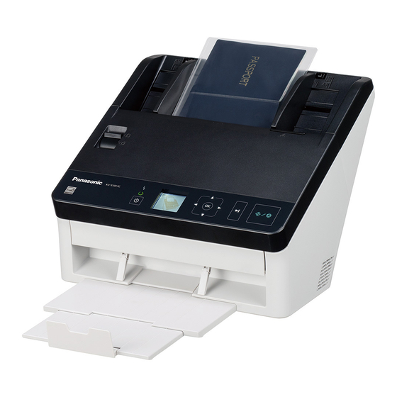
- Page 184 • The screen shots used in this manual may differ from the screens displayed on your computer. • The illustrations in this manual are based on the KV-S1057C. Trademarks • Microsoft, Windows, Windows Vista, and Internet Explorer are either registered trademarks or trademarks of Microsoft Corporation in the United States and/or other countries.
- Page 185 For details about viewing the help files, see "To view the help" (page 22). Software / Manual CD-ROM Contents — Device Driver — Drivers TWAIN — ISIS Panasonic proprietary application Applications Image Capture Plus for configuring advanced scanning settings — User Utility Utilities Scan Button Setting Tool —...
- Page 186 Introduction System Requirements Computer PC/AT or compatible machine with a CD-ROM drive ® Intel Core™ i5 2.5 GHz or higher ® Memory 4 GB or higher Interface USB 2.0 / USB 3.0 Note • For details about the system requirements, refer to [Read me first] in the Software / Manual CD-ROM. •...
- Page 187 Cleaning the Conveyor and Scanning Glasses ..............53 Cleaning the Double Feed Detectors and Starting Sensors ...........54 Cleaning the Rollers .......................55 Replacing the Rollers .....................60 Appendix ....................66 Troubleshooting ......................66 Error Messages (KV-S1057C and KV-S1027C only) .............69 Uninstalling the Software ....................70 Repacking Instructions ....................71 Specifications ........................72 Operating Manual...
- Page 188 Table of Contents Index......................74 Operating Manual...
-
Page 189: Before You Start
Before You Start Before You Start Installation Precautions • Do not place the unit in direct sunlight, in a cold Illegal Duplication draft, or near heating apparatus. • Do not place the unit near apparatus which It is unlawful to make duplication of certain generate electronic or magnetic noise. - Page 190 • For details about the roller cleaning paper, refer to the Material Safety Data Sheet (MSDS). Please ask your Panasonic sales company about obtaining the Material Safety Data Sheet. • To purchase the roller cleaning paper (KV-SS03), please contact your dealer, or call our Supplies and Accessories department at 1-800-726-2797 (U.S.A.
-
Page 191: Check The Accessories
Before You Start Check the Accessories Check that all accessories are included before installing the unit. In the event that an item is missing, please contact your dealer. Accessories Name Notes USB cable — Software / Drivers, Applications, Utilities, Documents Manual CD-ROM When the unit is shipped, this is stored in the Mixed batch card guide... -
Page 192: Location Of Controls
Location of Controls Main Unit Front Document guides Mixed batch card guide Manual feed selector Switches the scanning method between continuous scanning (Auto) and manual scanning (Manual). Operation panel For details, refer to "Operation Panel and LED Indicators" (page 14). Exit tray Exit extension tray 1 Exit extension tray 2... -
Page 193: Rear
Location of Controls Rear Security slot Use a commercially available security cable. USB connector USB cable Connect the USB cable to the scanner and the other end of the USB cable to the computer. Power cord AC inlet Operating Manual... -
Page 194: Operation Panel And Led Indicators
Location of Controls Operation Panel and LED Indicators nKV-S1057C and KV-S1027C nKV-SL1066, KV-SL1056, KV-SL1055, KV-SL1036 and KV-SL1035 A LED (Red) Lights when an error occurs. B LED (Green) Shows the scanner’s status. C Power button Press the power button for more than one second to turn the unit off. D Cursor button E Skip button If you press this button after a double feed is detected and scanning has been paused, the document... - Page 195 If you press this button after a double feed is detected and scanning has been paused, the document (or documents) detected as a double feed will be ejected from the scanner without being scanned. Scanning will stop. n KV-S1057C and KV-S1027C only G LCD H OK button If you are using the scanner with Image Capture Plus, you can perform a push scan using the LCD.
- Page 196 (except the power button) on the scanner’s operation panel to return to ready mode. The time until the scanner enters sleep mode can be changed in User Utility. For details about the error, refer to "Error Messages (KV-S1057C and KV-S1027C only)" (page 69) or check in User Utility. Operating Manual...
-
Page 197: Installation
Installation Required Space Around the Scanner In order to ensure proper operation, install the unit maintaining the proper distances from surrounding objects, as shown in the following illustration. 400 mm (16 in.) 238 mm (9.4 in.) 272 mm (10.7 in.) 750 mm (30 in.) 300 mm... -
Page 198: Installing The Software
Installation Installing the Software Notice • Make sure to connect the unit to your computer after installing the software. Connecting the unit to your computer and turning on the unit’s power before installing the software may influence the software installation. If you connect the unit to your computer and turn on the unit’s power before installing the software by mistake, install the software after disconnecting the unit from your computer. - Page 199 Installation If you selected [Custom] for the installation type in step 4, select the item that you want to install. Note • If you select TWAIN or ISIS, Image Capture Plus will also be installed. Follow the instructions on the screen and complete the installation. •...
-
Page 200: Installing The Unit
Installation Installing the Unit Remove all packing tape and cushioning. Pull out the feed extension tray in the direction of the arrow shown in the illustration below. Set the exit tray. Raise the exit stopper. Operating Manual... - Page 201 Installation Pull out the exit tray (A) and the exit extension trays (B, C). Notice • Do not forcefully pull out the exit stopper, the exit tray, or the exit extension trays. Doing so may damage them. Plug in the power cord and connect the USB cable. Press the power button to turn ON the unit’s power.
-
Page 202: Viewing Operating Manual And Help Installed
6.0 or later for Windows. ® For Image Capture Plus Select [All Programs] ® [Panasonic] ® [Image Capture Plus] ® [Image Capture Plus Help]. For User Utility or Scan Button Setting Tool Select [All Programs] ® [Panasonic] ® [Scanner Tools]. -
Page 203: Operation
Operation Preparing Documents Notice • Make sure to remove paper clips and staples from documents before scanning. Failing to do so can damage the unit, document, or both. • It is recommended to confirm that documents and cards are suitable for scanning (paper size, thickness, type, etc.) before scanning them. - Page 204 Operation Paper capacity for the feed tray: Number of Paper length (L) Combined thickness Paper weight sheets 64 g/m² (17 lb.) High-quality woodfree paper 54 mm £ L £ 297 mm 10 mm 75 g/m² (20 lb.) (2.1 in. £ L £ 11.7 in.) (0.4 in.) High-quality woodfree paper 80 g/m²...
-
Page 205: Compatible Card Types
Operation Compatible Card Types The compatible card types for this unit are as follows. ISO format card: 85.6 ´ 54 mm (3.4 ´ 2.1 in.) Size: Thickness: 0.76 mm (0.03 in.) • Embossed cards are also compatible. When scanning embossed cards, it is recommended to place them in landscape orientation with the side to be scanned facing up. -
Page 206: Compatible Bound Documents (Manual Scanning Only)
Operation Compatible Bound Documents (Manual Scanning Only) Bound documents can be scanned by setting the manual feed selector to manual scanning (Manual). You can use an optional carrier sheet (KV-SS076) to scan passports using manual scanning. Passport size: The passport sizes compatible with this unit are as follows. Width: 140 mm (5.5 in.) or less Length:... - Page 207 Operation Put the passport in a carrier sheet. • Open the passport (A) to the page you want to scan, and then put the thinner part (the opened half with less pages) in the carrier sheet (B) first, as shown in the illustration. •...
- Page 208 Operation Insert the carrier sheet (A) until it stops as shown in the illustration. Note • When manual scanning (Manual) is selected, make sure to insert the documents until they come into contact with the paper feed roller. Start scanning. Note •...
-
Page 209: Incompatible Documents
Operation Incompatible Documents The following types of documents may not scan properly: • Torn or frayed documents • Curled, wrinkled or folded documents • Carbon paper • Perforated or punched paper • Non-rectangular or irregularly shaped paper • Coated paper •... -
Page 210: Notes About Documents For Scanning
Operation Notes about Documents for Scanning • Depending on the paper type, scanning results may be poor when you scan incompatible documents, or even documents that should be compatible. If scanned images are skewed, paper jams occur, or double feeding occurs, try scanning again after doing the following: –... -
Page 211: Switching The Background Color Of Scanned Images
Operation Switching the Background Color of Scanned Images Using the software, you can switch the background color of scanned images between white and black. For details, refer to the Image Capture Plus, TWAIN, or ISIS help. Operating Manual... -
Page 212: Continuous Scanning (Auto) And Manual Scanning (Manual)
Operation Continuous Scanning (Auto) and Manual Scanning (Manual) You can select either continuous scanning (Auto) or manual scanning (Manual) by using the manual feed selector. Bound documents can be scanned by setting the manual feed selector to manual scanning (Manual). Continuous scanning (Auto) This setting is for feeding documents one page at a time automatically. -
Page 213: Mixed Batch Card Guide
Operation Mixed Batch Card Guide No adjustment to the document guide is required when using the mixed batch card guide. The mixed batch card guide prevents a card from skewing when scanning paper documents and a card simultaneously. Installing the mixed batch card guide The mixed batch card guide is stored inside the feed tray. - Page 214 Operation Attach the feed tray (A) to the unit. Attach the mixed batch card guide (A) to the unit. Operating Manual...
-
Page 215: Removing The Mixed Batch Card Guide
Operation Removing the mixed batch card guide Remove the mixed batch card guide as shown in the following illustration. Remove the mixed batch card guide (A) from the unit. Remove the feed tray (A) from the unit. • Remove the left side of the feed tray (B) first as shown in the illustration. Operating Manual... - Page 216 Operation Attach the mixed batch card guide (B) to the feed tray (A). Attach the feed tray (A) to the unit. Operating Manual...
-
Page 217: Using The Mixed Batch Card Guide
Operation Using the Mixed Batch Card Guide Set paper documents on the feed tray, and a card on the mixed batch card guide respectively. • The card set on the mixed batch card guide is fed after completing the paper document scanning. •... -
Page 218: Scanning Documents
Operation Scanning Documents Adjust the document guides (A) slightly larger than the actual size of the documents. Operating Manual... - Page 219 Operation Fan the documents. • Documents that have been stapled together or stacked together (as in a file folder) will need to be separated. Fan the stack of documents to separate all the edges. Hold both ends and bend the documents as shown in the illustration. To flatten the documents, hold firmly and pull them apart as shown in the illustration.
- Page 220 Operation Place the documents on the feed tray with the side to be scanned facing down. • Set the leading edge of documents as shown in the illustration (A). • Insert the documents slowly until they stop. Note • The height of the documents should not exceed the limit mark ( ) on the document guide.
- Page 221 Operation Hold the exit stopper and adjust the exit extension trays (A, B) to match the size of the scanned documents. Note • When the documents are curled or a paper jam occurs, fold up the exit guides (C) and then resume scanning.
-
Page 222: Performing A Push Scan
• Press and hold the OK button for more than 2 seconds to open the application setting screen. (KV-S1057C and KV-S1027C only) • Press and hold the Start/Stop button for more than 2 seconds to open the application setting screen. - Page 223 Push scan using the LCD If you are using a KV-S1057C or KV-S1027C with Image Capture Plus, you can perform a push scan using the LCD. Registered jobs are displayed on the LCD. Use the cursor button (A) to select a job.
- Page 224 Operation Push scan using the 7-segment LED If you are using a KV-SL1066, KV-SL1056, KV-SL1055, KV-SL1036 or KV-SL1035 with Image Capture Plus, you can perform a push scan using the 7-segment LED. A registered job number is displayed on the 7-segment LED.
- Page 225 Operation Checking events Check the following if an application does not start up after being set. Display the Scan properties screen. • If you are using Windows 8 / Windows 7: [Control Panel] ® [View devices and printers], right-click the scanner icon, and display the [Scan properties] screen.
-
Page 226: Using Control Sheets
Operation Using Control Sheets Placing a control sheet in the middle of documents lets you change the scanning conditions for pages scanned after the control sheet. Also, you can change the folder used to save the scan data of documents scanned after the control sheet. -
Page 227: About Printing Control Sheets
Operation About Printing Control Sheets • Print the control sheet at the specified size; do not enlarge or reduce the size. • When printing the control sheet, make sure that the pattern is 25 mm (1 in.) from the top of the page and centered horizontally. -
Page 228: Clearing Paper Jams
Clearing Paper Jams Clearing Paper Jams Torn paper, thin paper or paper that is creased on the top edge may cause paper jams. If a paper jam occurs, remove the jammed sheet according to the following procedure. Remove all documents from the feed tray. Press the ADF door release (A), and open the ADF door (B). - Page 229 Clearing Paper Jams • If the document is jammed in the exit area, pull it forward as shown in the illustration. Close the ADF door. • Push both sides of the ADF door down slowly until it clicks into place. Notice •...
-
Page 230: Care And Maintenance
Care and Maintenance Cleaning the Outside of the Scanner Notice • Before moving the unit, be sure to unplug the power cord and USB cable. • Do not use commercially available cleaners, detergent, thinner, or benzine. (Doing so may cause deformation, discoloration or damage.) •... -
Page 231: Cleaning The Inside Of The Scanner
Care and Maintenance Cleaning the Inside of the Scanner Note • Clean the inside of the scanner when approximately 6,000 sheets have been scanned. The time for cleaning may differ depending on documents you scan. To maintain proper scanning, clean the scanner parts frequently. - Page 232 Care and Maintenance Clean the conveyor, scanning glasses, double feed detectors, starting sensors and rollers. • Clean the parts in the following order: conveyor and scanning glasses, double feed detectors and starting sensors, rollers. • For details about cleaning, refer to the following: –...
-
Page 233: Cleaning The Conveyor And Scanning Glasses
Care and Maintenance Cleaning the Conveyor and Scanning Glasses With a soft and dry cloth, wipe off any dirt on the conveyor (A) and scanning glasses (B). Operating Manual... -
Page 234: Cleaning The Double Feed Detectors And Starting Sensors
Care and Maintenance Cleaning the Double Feed Detectors and Starting Sensors Remove dust from the double feed detectors (A) and starting sensors (B) with a cotton swab. Operating Manual... -
Page 235: Cleaning The Rollers
Care and Maintenance Cleaning the Rollers Use the roller cleaning paper (KV-SS03) (page 10) to wipe dirt off from the surfaces of all rollers. Notice • Be careful not to damage any parts of the unit. Open the double feed prevention roller cover (A). Remove the double feed prevention roller. - Page 236 Care and Maintenance Use the roller cleaning paper to clean the surface of the double feed prevention roller. • Wipe the entire surface of both rollers. Install the double feed prevention roller. • Align the shaft that is shaped as indicated by A with the notch in the roller mount (B), and then insert the shaft in the notch.
- Page 237 Care and Maintenance Close the double feed prevention roller cover (A) firmly. Notice • Be sure to close the double feed prevention roller cover until it clicks into place. Open the paper feed roller cover (A). Operating Manual...
- Page 238 Care and Maintenance Use the roller cleaning paper to clean the paper feed roller. • Wipe the rollers from one end to the other (in the direction of the arrow) all the way around them, as shown in the illustration. Close the paper feed roller cover firmly.
- Page 239 Care and Maintenance Use the roller cleaning paper to clean the surface of the conveyor rollers (A) and exit rollers (B). • Wipe the rollers from one end to the other (in the direction of the arrow) all the way around them, as shown in the illustration.
-
Page 240: Replacing The Rollers
Care and Maintenance Replacing the Rollers As a rough guideline, we recommend to replace the paper feed roller and double feed prevention roller module after scanning 250,000 sheets of paper. ("250,000 sheets" is based on scanning high-quality woodfree paper. Depending on the type of paper and other factors, the actual lifetime for the rollers will differ.) In User Utility, you can check the number of sheets that have been scanned. - Page 241 Care and Maintenance Remove the double feed prevention roller. • While pushing the latch (A) to the right side as the direction indicated by the arrow, remove the double feed prevention roller (B) in the direction of the arrow. Then, pull out the left shaft (when facing it) from the notch in the roller mount.
- Page 242 Care and Maintenance Close the double feed prevention roller cover (A) firmly. Notice • Be sure to close the double feed prevention roller cover until it clicks into place. Open the paper feed roller cover (A). Operating Manual...
- Page 243 Care and Maintenance Lift up the gear (A) on the left side of the paper feed roller, and then remove the paper feed roller. Remove the rubber rollers from the paper feed roller shaft. • Push the tab (A) to remove the rubber roller (B) from the paper feed roller shaft. Remove the other rubber roller (C) in the same way.
- Page 244 Care and Maintenance Take out the new paper feed roller in the optional roller exchange kit. Install the two new rubber rollers onto the paper feed roller shaft. • After confirming the tabs (A) of both rubber rollers are facing outwards, insert the rubber rollers onto the paper feed roller shaft until they click into place.
- Page 245 Care and Maintenance Close the paper feed roller cover (A) firmly. Notice • Make sure to close both sides of the paper feed roller cover until they click into place. • After installing the paper feed roller, confirm that the paper feed roller can rotate in the feeding direction.
-
Page 246: Appendix
Appendix Troubleshooting If a problem occurs while the scanner is being used, check the following items and check the scanner status in User Utility. If the unit still malfunctions, turn it OFF, unplug the power cord and call for service. Symptom Possible Cause Remedy... - Page 247 Appendix Symptom Possible Cause Remedy The paper feed roller or double feed Replace the paper feed roller or prevention roller have become worn double feed prevention roller. down. (page 60) Clean the double feed detectors. The double feed detectors are dirty. (page 54) Right and left sides of the document Flatten the document (page 24) and...
- Page 248 Appendix Symptom Possible Cause Remedy The image for a scanned The document to be scanned was Load the document correctly. document is blank. loaded upside down. (page 38) Vertical streaks appear on the Clean the scanning glasses. The scanning glasses are dirty. scanned document.
-
Page 249: Error Messages (Kv-S1057C And Kv-S1027C Only)
Appendix Error Messages (KV-S1057C and KV-S1027C only) Error codes corresponding to the scanner status are displayed on the LCD. Also, when the scanner is connected to a computer, simple messages are displayed on the LCD. For details about the error codes and messages, check in User Utility. -
Page 250: Uninstalling The Software
In Windows XP, select [Add or Remove Programs]. Uninstall the following software programs. Program Name Publisher Image Capture Plus Panasonic System Networks Co., Ltd. Scan Button Setting Tool Panasonic System Networks Co., Ltd. IDR Engine Panasonic System Networks Co., Ltd. -
Page 251: Repacking Instructions
Appendix Repacking Instructions It is highly recommended that you keep the original carton and ALL packing materials. If you need to transport or ship the scanner, please follow these instructions. Note • Improper repacking of the scanner may result in a service charge to repair the scanner. •... -
Page 252: Specifications
The scanning speed differs depending on the host computer, the operating system, the application, the measuring method, the quantity of data in the image, and the paper type. The scanning speed depends on a measuring method of Panasonic. For details, see "Compatible Paper Types". - Page 253 8 W or less 8 W or less 8 W or less Power consumption 3.0 W or less (For KV-S1057C and KV-S1027C) (For AC100 – Sleep 2.9 W or less (For KV-SL1066, KV-SL1056, KV-SL1055, KV-SL1036 and 125 V models) KV-SL1035) Power OFF 0.5 W or less...
- Page 254 Index Index OK button Operating Environment Operation panel 12, 14 Numerics 7-segment LED 2, 15, 44 Paper feed roller Power button AC inlet Power cord 11, 13 Accessories Push Scan 3, 42 ADF door ADF door release Quick Installation Guide 5, 11 Background color switch function 2, 3, 31...
- Page 255 © Panasonic System Networks Co., Ltd. 2014 PNQX6995ZA DD0914HS0...
Need help?
Do you have a question about the KV-S1057C and is the answer not in the manual?
Questions and answers