
Related Manuals for AAON SS1113


Summary of Contents for AAON SS1113
- Page 1 Main Chiller Controller Technical Guide Main Chiller Controller Code: SS1113, Version 1.00 and later Requires Touch Screen Software, Version 1.00 and later Requires Prism 2 Software, Version 4.8.3 and later...
- Page 2 ® ® Factory Technical Support Phone: 918-382-6450 AAON, Inc., Tulsa, OK. It is the intent of AAON to provide accurate and current Turbocor is a registered trademark of Danfoss Commercial ® product information. However, in the interest of product Compressors, S.A., Tallahassee, FL...
- Page 3 AAON Factory Technical Support: 918-382-6450 techsupport@aaon.com NOTE: Before calling Technical Support, please have the model and serial number of the unit available. PARTS: For replacement parts please contact your local AAON Representative. TURBOCOR CONTROL SYSTEM ® PART DESCRIPTION AAON P/N...
-
Page 4: Table Of Contents
TABLE OF CONTENTS OVERVIEW ............................6 Control System Features & Applications ........................6 Manual Overview ..............................6 TOUCH SCREEN INTERFACE ......................7 Main Screen, Overview Screen & Trending Screen ....................8 Status Screens ................................. 9 Password & Login Screens ............................ 10 Setpoint Screens .............................. - Page 5 TABLE OF CONTENTS ECONOMIZER SUBCOOL MODULE SEQUENCE OF OPERATION ..........24 Points of Information and Control .......................... 24 Sequence ................................24 FAULTS ............................24 INSTALLATION & WIRING ......................26 Main Chiller Controller Inputs & Outputs ........................ 26 Chiller Expansion Module Inputs & Outputs ......................26 Compressor Circuit Module Inputs &...
-
Page 6: Overview
OVERVIEW Features & Applications Control System Features & Applications Manual Overview The G015540 Main Chiller Controller is only used with Turbocor ® This guide will lead you through each section of the Main Chiller Compressors in Chiller Operation. The Controller is designed with 8 Controller Technical Guide. -
Page 7: Touch Screen Interface
SECTION 1: TOUCH SCREEN INTERFACE Touch Screen Features Features The Touch Screen provides the following useful functions: • Utilizes a graphical touch screen menu system with The main operator interface to the Turbocor Chiller Controller is a easy-to-understand menu options Panel PC (PPC) with a touch screen overlay. -
Page 8: Main Screen, Overview Screen & Trending Screen
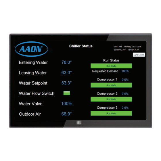
Screen ID Software Version touch screen will trend data at this rate. Trend logs can be If these items show all zeros, contact AAON Technical Support. found in the Chiller folder in a folder called, Trendlogs. <Sync Clocks> button below the time and date display will Press <DONE>... -
Page 9: Status Screens
SECTION 1: TOUCH SCREEN INTERFACE Status Screens Compressor Status Screens Economizer Status Screen Press the <Economizers> icon to access the Press the <Compressors> icon to access the Economizer Status Screen. See Figure 7. Press Compressor Status Screens. See Figure 5. There are 2 <DONE>... -
Page 10: Password & Login Screens
SECTION 1: TOUCH SCREEN INTERFACE Password Setup and Login Screen Accessing Setpoint Screens Please note: You DO NOT have to setup a password or username. <Cancel> You can, optionally, press at the Password Setup Screen; however, this will leave the setpoints unprotected. Press the <Setpoints>... -
Page 11: Setpoint Screens
SECTION 1: TOUCH SCREEN INTERFACE Setpoint Screens Temperature Setpoint Screen When you access a setpoint fi eld in any Setpoints Screen, the data entry screen for that setpoint will appear, allowing you to use the data entry keypad to change the value. The screen displays the name <Temperatures>... - Page 12 SECTION 1: TOUCH SCREEN INTERFACE Setpoint Screens Miscellaneous Setpoint Screens Calibration Setpoint Screen <Miscellaneous> <Calibration> Press the icon to access the Press the icon to access the Calibration <DONE> Miscellaneous Setpoint Screens. See Figure 16. Click Setpoint Screen. See Figure 18. Press the right arrow at the top right of the screen to access return to the Chiller Status Screen or select another the second screen.
-
Page 13: Faults/Alarms Screens
SECTION 1: TOUCH SCREEN INTERFACE Setpoint & Alarm Screens Confi gurations Setpoint Screen On the Main Faults Screen, if there are one or more faults present, the box next to each active fault will appear red. From the bottom of this screen you can access the Compressor alarms. -
Page 14: Lists Of Status Points, Setpoints, And Faults / Alarms
SECTION 1: TOUCH SCREEN INTERFACE Status Points & Setpoints List Economizers NOTE: The lists that follow are all of the status. setpoints, • Expansion Valve Position • Coil Temp and alarm items categorized per each screen in the Touch Screen Program. •... - Page 15 SECTION 1: TOUCH SCREEN INTERFACE Setpoints & Faults/Alarms List Alarms & Faults Miscellaneous • 1 Compressor On Max Speed Reset Limit Main Faults • 1 Compressor On Min Speed Reset Limit • Water Flow Fault • EM1 Board Missing • 1 Compressor On Max Liquid Level Limit •...
- Page 16 SECTION 1: TOUCH SCREEN INTERFACE Alarms & Faults List Compressor 1-3 Alarms Compressor 1-3 Bearing Motor Faults • Inverter Temperature Alarm (0) • Motor Single Phase Overcurrent Fault (0) • Not Valid (1) • DC Bus Overvoltage Fault (1) • Suction Pressure Alarm (2) •...
-
Page 17: Troubleshooting
SECTION 1: TOUCH SCREEN INTERFACE Troubleshooting Touch Screen Troubleshooting Sync Clock • In the event of the Main Controller being powered down Updating the Touch Screen for a long time (week or longer), it will lose its time and <Sync Clocks> date so you will need to press located on •... -
Page 18: Main Chiller Controller Sequence Of Operation
Zone SECTION 2: SEQUENCE OF OPERATIONS Zone Main Chiller Controller Operation Main Chiller Controller Operation Startup 1. The Controller will wait for one of (4) run The chiller system consists of two primary systems: commands: Refrigeration Loop Control 1.1 Remote Start/Stop activation Wet Contact on Binary Input #1 of the Main Controller 1.1. -
Page 19: Modulation
SECTION 2: SEQUENCE OF OPERATIONS Main Chiller Controller Operation • No Turbocor Faults are active for the designated Select the compressor to shut down based on whether lead/ ® compressor activating. lag or sequential operation is selected: • If this is not the fi rst compressor to start, •... -
Page 20: Compressor Faults
Zone SECTION 2: SEQUENCE OF OPERATIONS Zone Main Chiller Controller Operation Modulation Remove the run enable signal from all compressor modules and economizer modules. The compressors Obtain the pressure ratio from each running will run their auto-shutdown sequence and will ignore Compressor Circuit Module. -
Page 21: Shutdown
SECTION 2: SEQUENCE OF OPERATIONS Vestibule Fan-Coil Control Sequence Vestibule Fan-Coil Control Sequence • From the current minimum and maximum levels, a reset function will be enacted based on the current demand. The purpose of the fan-coil control is to manage the environmental conditions in the vestibule on the chiller. -
Page 22: Compressor Circuit Module Sequence Of Operation
Zone SECTION 2: SEQUENCE OF OPERATIONS Zone Compressor Circuit Module Operation Compressor Circuit Module Sequence The sequence consists of several sub-sequences: The Compressor Circuit Module performs the following functions: • Load Balance/Startup Bypass Valve • Controls the operation of the compressor via communications with the compressor control •... -
Page 23: Compressor Control
SECTION 2: SEQUENCE OF OPERATIONS Compressor Circuit Module Operation Compressor Control Modulation Compressor control is managed based on demands and utilizes the The Compressor-Demand is forwarded to the Compressor Circuit Modules. While this sequence is based on the compressor. Danfoss Turbocor Compressor Controller Manual, that manual ®... -
Page 24: Economizer Subcool Module Sequence Of Operation
Zone SECTION 2: SEQUENCE OF OPERATIONS Zone Economizer Subcool Module & Main Faults Economizer Subcool Module Fault Detection The Main Chiller Controller continuously performs self diagnostics The Economizer Subcool Module manages the superheat of the during normal operation to determine if any operating failures have sub-cooler to a settable limit. - Page 25 SECTION 2: SEQUENCE OF OPERATIONS Main Faults Exp Lost - Expansion Board Lost Fault Disabled - Compressor Disabled Fault Chiller Expansion Module Missing This fault is generated by removing the Binary Input Enable signal Compressor Module #1 Missing from the Compressor Module board. This is a manual method of Compressor Module #2 Missing locking out a Compressor for maintenance or other operational Compressor Module #3 Missing...
-
Page 26: Installation & Wiring
Zone SECTION 3: WIRING Zone Main Chiller Controller & Expansion Module Input/Output Maps Input/Output Map CHILLER EXPANSION MODULE See Table 1 for the Main Chiller Controller InputsOutputs and Analog Inputs Table 2 for the Chiller Expansion Inputs/Outputs. Vestibule Temperature Sensor (T1) Liquid Line Temperature Sensor (T2) MAIN CHILLER CONTROLLER Chiller Enable (0-5VDC) (T3) -
Page 27: Compressor Circuit Module Inputs & Outputs
SECTION 3: WIRING Compressor Circuit & Economizer Subcool Module I/O Maps Input/Output Map ECONOMIZER SUBCOOL MODULE See Table 3 for the Compressor Circuit Module Inputs/Outputs Analog Inputs and Table 4 for the Economizer Subcool Module Inputs/Outputs. Economizer Suction Pressure (0-5V) (SIG 1 Input) COMPRESSOR CIRCUIT MODULE Economizer Suction Temperature Sensor... -
Page 28: Main Chiller Controller Input Wiring
Zone SECTION 3: WIRING Zone Main Chiller Controller Input Wiring Main Chiller Controller Inputs The Main Chiller Controller provides Compressor demand management, Condenser control, and Expansion Valve control of the Turbocor Compressor in Chiller operation. ® The G015540 Main Chiller Controller is only used with Turbocor ®... -
Page 29: Main Chiller Controller Output Wiring
SECTION 3: WIRING Main Chiller Controller Output Wiring Main Chiller Controller Outputs The Main Chiller Controller must be connected to 18-30 VAC as shown in Figure 25, below. Please see Table 8, page 40 for correct VA requirements to use when sizing the transformer(s) used for The Main Chiller Controller has (2) E-BUS Expansion Ports which powering the Controller. -
Page 30: Chiller Expansion Module Wiring
Zone SECTION 3: WIRING Zone Chiller Expansion Module Wiring Chiller Expansion Module The Chiller Expansion Module provides the following features: • Vestibule Temp Control The G015550 Chiller Expansion Module is used only with Turbocor ® Compressors in Chiller operation. The Chiller Expansion Module •... -
Page 31: Compressor Circuit Module Wiring
SECTION 3: WIRING Compressor Circuit Module Wiring Compressor Circuit Module Wiring The Compressor Circuit Module provides the following features: • Controls the operation of the Compressor via The G015560 Compressor Circuit Module is used only with communications with the compressor control board. Turbocor Compressors in Chiller operation. -
Page 32: Economizer Subcool Module Wiring
Zone SECTION 3: WIRING Zone Economizer Subcool Module Wiring Economizer Subcool Module Wiring The Economizer Subcool Module provides the following features: • Modulates the MCS Economizer Expansion Valves to The G015570 Economizer Subcool Module is used only with maintain the Superheat Setpoint of the Sub-Cooler. Turbocor ®... -
Page 33: Troubleshooting
SECTION 4: TROUBLESHOOTING Main Chiller Controller Components Figure 29: Main Chiller Controller Components Main Chiller Controller Technical Guide... -
Page 34: Main Chiller Controller & Chiller Expansion Module Led Locations
Zone SECTION 4: TROUBLESHOOTING Zone Main Chiller Controller & Expansion Module LED Diagnostics Main Chiller Controller LEDs Binary Input LEDs BIN1 - This green LED will light up when the Remote Start/Stop The Main Chiller Controller is equipped with LEDs that can be used contact is closed. - Page 35 SECTION 4: TROUBLESHOOTING Main Chiller Controller & Expansion Module LED Diagnostics Figure 30: Main Chiller Controller LED Locations Figure 31: Chiller Expansion Module LED Locations Main Chiller Controller Technical Guide...
-
Page 36: Compressor Circuit Module & Economizer Subcool Module Led Locations
Zone SECTION 4: TROUBLESHOOTING Zone Compressor Circuit & Economizer Subcool Module LED Diagnostics Using LEDs To Verify Operation Binary Input LEDs - This green LED will light up when the Compressor Disable BIN1 The Modules are equipped with LEDs that can be used to verify contact is closed. -
Page 37: Thermistor Temperature Sensor Testing
SECTION 4: TROUBLESHOOTING Thermistor Sensor Testing Temperature/Resistance for Temperature – Resistance – Voltage for Type Thermistor Sensors III 10 K Ohm Thermistor Sensors Temp Temp Resistance Voltage @ Input (VDC) (ºF) (ºC) (Ohms) The following sensor voltage and resistance table is provided to aid in checking sensors that appear to be operating incorrectly. -
Page 38: Suction Pressure Transducer Testing
Zone SECTION 4: TROUBLESHOOTING Zone Suction Pressure Transducer Testing Suction Pressure Transducer Testing Suction Pressure Transducer for R134a Refrigerant – Temp/Pressure/Voltage Chart for R134a Refrigerant 0-200 PSI The Evaporator Coil Temperature is calculated by converting the Suction Pressure to Temperature. The Suction Pressure is obtained by using the Suction Pressure Transducer, which is connected into the Suction Line of the Compressor. -
Page 39: Discharge Pressure Transducer Testing
SECTION 4: TROUBLESHOOTING Discharge Pressure Transducer Testing Discharge Pressure Transducer Discharge Pressure Transducer Testing 0-500 PSI – Temp/Pressure/Voltage Chart for R134a Refrigerant 0-500 PSI The Discharge Pressure is obtained by using the Discharge Pressure Transducer, which is connected into the Discharge Line of the Compressor. -
Page 40: Important Wiring Considerations
Correct wiring of the Main Chiller Controller and its modules is the most important factor in the overall success of the controller installation process. The Main Chiller Controllers and Modules are factory installed and wired at the AAON ® factory. Some of the... - Page 41 Main Chiller Controller, and its associated modules. wire that meets this specifi cation and is color coded for the network or local loop. Please consult your AAON All wiring is to be in accordance with local and national distributor for information.
-
Page 42: Appendix A - Lcd Display Screens
APPENDIX A - MAIN CHILLER CONTROLLER LCD SCREENS Navigation Keys & Main Screens Map LCD Display Screen & Navigation Main Screens Map Keys Refer to the following map when navigating through the Main Screens. The fi rst screen is an initialization screen. To scroll through The LCD display screens and buttons allow you to view status <MENU>... - Page 43 APPENDIX A - MAIN CHILLER CONTROLLER LCD SCREENS Settings Screens Settings Screens Refer to the following map when navigating through the Settings DEVICEID Screens. From the Settings Screen, press <ENTER> to scroll through XXXXXXX the screens. Settings ® BACnet - CURRENT DEVICE ID A Device ID of up to 7 digits can be entered.
- Page 44 APPENDIX A - MAIN CHILLER CONTROLLER LCD SCREENS Status Screens Status Screens EntWater XX.X Refer to the following map when navigating through the Status Screens. From the Status Screen, press <ENTER> to scroll through the screens. ENTERING WATER TEMPERATURE Status Oat Temp XX.X OperMode...
- Page 45 APPENDIX A - MAIN CHILLER CONTROLLER LCD SCREENS Alarm Screens Alarm Screens ExValve XXX% If there are no Alarms, the Alarm Screen will display “No Alarms.” If there are alarms present, the screen will display, “Alarms.” You <ENTER> can press to scroll through the alarms or you can let the EXPANSION VALVE POSITION alarms automatically scroll on the screen.
-
Page 46: Compressor Circuit Module Lcd Screens
APPENDIX A - COMPRESSOR CIRCUIT MODULE LED SCREENS Main Screen Map & Module Screens Main Screens Map Module Screens Refer to the following map when navigating through the LCD Main Refer to the following map when navigating through the Compressor <MENU>... -
Page 47: Economizer Subcool Module Lcd Screens
APPENDIX A - COMPRESSOR CIRCUIT MODULE LED SCREENS System Status Screens System Status Screens SPEED XXXXRPM Refer to the following map when navigating through the System <ENTER> Status Screens. From the SYSTEM STATUS Screen, press to scroll through the screens. SPEED RPM 4200 RPM SYSTEM... - Page 48 APPENDIX A - COMPRESSOR CIRCUIT MODULE LED SCREENS Sensor Status Screens Sensor Status Screens DIS TEMP XX.X F Refer to the following map when navigating through the Sensor Status <ENTER> Screens. From the SENSOR STATUS Screen, press scroll through the screens. DISCHARGE TEMPERATURE SENSOR STATUS...
- Page 49 APPENDIX A - COMPRESSOR CIRCUIT MODULE LED SCREENS Turbocor Info Screen Turbocor Info Screens Refer to the following map when navigating through the Turbo Info <ENTER> Screens. From the TURBOCOR INFO Screen, press MIN SPD scroll through the screens. XXXXRPM TURBOCOR INFO MINIMUM COMPRESSOR SPEED FEEDBACK...
- Page 50 APPENDIX A - COMPRESSOR CIRCUIT MODULE LED SCREENS Alarms Screen Alarms Screen If an alarm is present, the ALARM LED above the LCD display will light up red and blink. Th e Alarms will display and scroll automatically from the ALARMS screen when alarms are present. NO ALARMS ACTIVE ALARMS! NO ALARMS...
- Page 51 APPENDIX A - ECONOMIZER SUBCOOL MODULE LCD SCREENS Main Screen Map & Module Screens Main Screens Map Module Screens Refer to the following map when navigating through the LCD Main Refer to the following map when navigating through the RSMV <MENU>...
- Page 52 APPENDIX A - ECONOMIZER SUBCOOL MODULE LCD SCREENS System Status Screens System Status Screens SUPRHEAT XX.X F Refer to the following map when navigating through the System <ENTER> Status Screens. From the SYSTEM STATUS Screen, press to scroll through the screens. CURRENT SUPERHEAT CALCULATION SYSTEM STATUS...
- Page 53 APPENDIX A - ECONOMIZER SUBCOOL MODULE LCD SCREENS Alarms Screen Alarms Screen If an alarm is present, the ALARM LED above the LCD display will light up red and blink. Th e Alarms will display and scroll automatically from the ALARMS screen when alarms are present. NO ALARMS ACTIVE ALARMS! NO ALARMS...
- Page 54 APPENDIX B - BACnet ® BACnet Connection To MS/TP Network ® Figure 34: BACnet Connection to MS/TP Network ® Main Chiller Controller Technical Guide...
-
Page 55: Parameters
APPENDIX B - BACnet ® BACnet Parameters ® ANALOG INPUTS BACnet BACnet ® ® Point Name Object Description Limits Application AI:1 Current version of the software in the unit. Software Version Operating Mode AI:2 Current Occupied/Startup Status Off Mode (0) Initial Start Delay (1) Run Mode (2) Leaving Water... - Page 56 APPENDIX B - BACnet ® BACnet Parameters ® ANALOG INPUTS BACnet BACnet ® ® Point Name Object Description Limits Economizer #1 AI:23 Economizer #1 Superheat Superheat Economizer #2 AI:24 Economizer #2 Expansion Valve Position Expansion Valve Economizer #2 AI:25 Economizer #2 Suction Pressure Suction Pressure Economizer #2 AI:26...
- Page 57 APPENDIX B - BACnet ® BACnet Parameters ® ANALOG INPUTS BACnet BACnet ® ® Point Name Object Description Limits Comp #1 Condenser AI:45 Compressor #1 Condenser Ratio Ratio Comp #1 Motor AI:46 Compressor #1 Motor Current Current Comp #1 Faults AI:47 Compressor #1 Faults See Fault Bits on page 58.
- Page 58 APPENDIX B - BACnet ® BACnet Parameters ® ANALOG INPUTS BACnet BACnet ® ® Point Name Object Description Limits Comp #3 Suction AI:70 Compressor #3 Suction Line Temperature Line Temperature Comp #3 Discharge AI:71 Compressor #3 Discharge Pressure Pressure Comp #3 Saturated AI:72 Compressor #3 Saturated Discharge Temperature Discharge Temp...
- Page 59 APPENDIX B - BACnet ® BACnet Parameters ® BINARY INPUTS BACnet Object BACnet ® ® Point Name Description Remote Start/Stop BI:1 Wet Contact to Activate Run Mode Wet Contact Water Flow BI:2 Wet Contact to Indicate Water Flowing in the Loop Proving Wet Contact Emergency Stop...
- Page 60 APPENDIX B - BACnet ® BACnet Parameters ® BINARY INPUTS BACnet Object BACnet ® ® Point Name Description Condenser Fan BI:24 Current Status of Confi gurable Relay #5 on Main Board Bank #5 Alarm Indicator BI:25 Current Status of Confi gurable Relay #6 on Main Board On Board Relay 7 BI:26 Not Used...
- Page 61 APPENDIX B - BACnet ® BACnet Parameters ® ANALOG VALUES BACnet Object BACnet Limit Range ® ® Point Name Description Vestibule AV:9 If the Vestibule Temperature drops below this setpoint 50-90 Heating the heating mode will activate on the Fan Coil. Setpoint Vestibule Heat/ AV:10...
- Page 62 2425 So. Yukon Ave • Tulsa, OK • 74107-2728 Ph: (918) 583-2266 • Fax: (918) 583-6094 AAON Part No.: G019150, Rev. 01A ® Printed in the USA • © August 2018 AAON • All Rights Reserved...
Need help?
Do you have a question about the SS1113 and is the answer not in the manual?
Questions and answers