Advertisement
Advertisement

Summary of Contents for BWT Liff Powermag PM100S
- Page 1 Installation & Operating Instruction Manual...
-
Page 2: Table Of Contents
Contents 1. General Notes ...............3 2. Installation ................4 3. Electrical Notes ..............7 4. Troubleshooting Guide ............9 5. Spare Parts List ..............9 6. Specifications ..............10 7. Warranty Information ............11... -
Page 3: General Notes
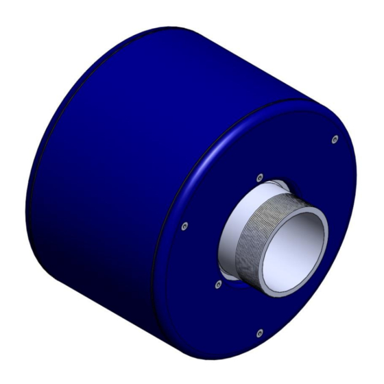
1. General Notes Powermag is a WRAS approved electromagnetic physical water conditioner that utilises a powerful electromagnetic field to inhibit hard crystalline scale formation in hot and cold water systems. The Powermag induces a specific magnetic field within the water path that has a physical effect on the hardness minerals within the water supply. -
Page 4: Installation
2. Installation Powermag must be installed by a professional installer The device should be installed directly in-line on pipework in any of the following materials; stainless steel, galvanized steel, copper or plastic. To ensure that the device is adequately supported and does not place excessive strain on the existing pipework, we recommend using additional support brackets (not supplied) on the inlet and outlet pipework. - Page 5 Recommended Installations Powermag units are best installed in one of the following positions: Gravity feed from a central water tank After a booster pump Directly on the cold mains supply, where all outlets are mains fed Isolation Valve Water Tank...
- Page 6 Key to LCD Display Running Temperature: Temperature reading from the thermistor on the Activity outlet pipework Display Display Coil Current: Operating current of electromagnet Hours Run: Total hours of coil operation since installation Set Temperature: Maximum temperature setting for thermistor circuit ...
-
Page 7: Electrical Notes
3. Electrical Notes Identifying the main components Power Supply PCB Control Assembly Coil DC Mains AC inc. smoothing capacitor and bridge Display rectifier Supply Supply Connection Power Terminal Transformer Block... - Page 8 Connection Terminals Connect terminals marked L (Live), N (Neutral) and E (Earth) on the right of the terminal box to the fused switched spur for the mains power supply (using the flying lead supplied with the panel or similar) ...
-
Page 9: Troubleshooting Guide
Isolation Switch PMMI30 6A MCB (Mains Supply MCB) PMCB6 10A MCB (PM100 only) PMCB10 16A MCB (Coil Supply MCB) PMCB16 Control PCB Display PMDISPLAY Thermistor with lead PMTHL For spare parts please contact BWT on 01494 838100 or email commercialuk@bwt-uk.co.uk... -
Page 10: Specifications
6. Specifications Mechanical Specification Specification PM100S PM150S PM200S PM250S PM300S PM400S / Model Pipe Size 1” 1.5” 2” 2.5” 3” 4” (BSP male) Coil diameter (mm) Coil width (mm) Overall length (mm) Coil weight (kg) Max flow rate 12.0 (l/sec) Frictional loss <0.2 <0.2... -
Page 11: Warranty Information
Powermag supplied by BWT UK (or its agents) within the United Kingdom (UK Mainland only) where it is shown to the satisfaction of BWT UK to be defective due to faulty workmanship or materials within the warranty period (12...


Need help?
Do you have a question about the Liff Powermag PM100S and is the answer not in the manual?
Questions and answers