Table of Contents
Advertisement
Working Condition and Specification
1.1 Working Condition:
Power supply: AC220V±10%
Frequency: 50HZ±0.5
Humidity: <85%
Environment Temperature: 0℃~+40℃
Magnetic Field: <400A/m
Spark and fire is prohibited.
2.2 Specifications:
Fuel Tank Capacity: 2000 ml
Capacity of Measuring Cylinder: 125 ml
Speed Range: 0~7500 rpm
Injecting Times: 0~9900 Step: 100ms
PWM Pulse: 0~20.0 ms Step: 0.1 ms
System Pressure: 0~0.6Mpa (adjustable)
Time: 0~20 minute (adjustable)
Power of Ultrasonic Cleaning: 70W
Frequency of Ultrasonic Cleaning: 28 KHZ±0.5 KHZ
- - 1 - -
Advertisement
Table of Contents

Related Manuals for Autool CT-200


Summary of Contents for Autool CT-200
- Page 1 Working Condition and Specification 1.1 Working Condition: Power supply: AC220V±10% Frequency: 50HZ±0.5 Humidity: <85% Environment Temperature: 0℃~+40℃ Magnetic Field: <400A/m Spark and fire is prohibited. 2.2 Specifications: Fuel Tank Capacity: 2000 ml Capacity of Measuring Cylinder: 125 ml Speed Range: 0~7500 rpm Injecting Times: 0~9900 Step: 100ms PWM Pulse: 0~20.0 ms Step: 0.1 ms System Pressure: 0~0.6Mpa (adjustable)
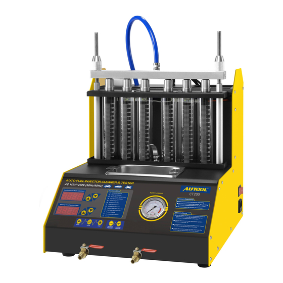
- Page 2 II Structure 2.1 Structure 1. Fasten bolt 2. Fuel distributor 3. Ultrasonic trough 4. Pressure meter 5. Measuring 6. Power switch 7. Operation panel 8. fuel outlet valve 2.2 Operation Panel 1. LED screen - - 2 - -...
- Page 3 2. Start: To run the function that selected; 3.Arrowkey: To adjust pulse working time and injection times; 4. PAUSE 5. Arrow key: To select function item and adjust pulse width ; 6. STOP 7. Pressure down 8. Pressure up 9. Pressure Meter Ⅲ...
- Page 4 2)Connect the machine to power supply and turn it on. 3)Put the cleaning frame on the ultrasonic groove, and put the injector into the whole of the frame. 3.1.2 Steps 01 Ultrasonic Cleaning 1)Pour proper quantity cleaning fluid into ultrasonic groove. 2)Connect the actuation cable to the injector needed to be cleaned.
- Page 5 3.2.1 Preparation 1) Pour about 1900ML test fluid into the machine through measuring cylinder. 2) Install the injector Installation of Up-inlet Injector a. Take the coupler and plugs from the toll drawer and install them to fuel distributor. b. Put some grease on the “O”ring of the injector, and install it into the coupler of the fuel distributor.
- Page 6 Installation Diagram a. Select the suitable coupler④ and “O” loop③, and then put the “O” loop on the coupler. (Put a little lubricant on the coupler and the “O”loop.) b. Put the injector⑨ into the coupler, and then put them together into the fuel distributor⑥.
- Page 7 key. 3) Press Left or Right Arrow key to set up working time. (Normally, it is 2 minutes.) 4) Press RUN key. 5) Turn Pressure Adjusting Knob until the pressure is 0.25-0.3MPa.. 6) Press Left or Right Arrow key to select proper injection pulse (default value is 3MS).
- Page 8 seconds.) 2. System will automatically simulate 3 times accelerating cycle from 750 RPM to 7500 RPM to test the injection condition of the injector. 06 Shifting Speed Test 1) Press Left or Right Arrow key to select Shifting Speed Test. 2) Press RUN key.
- Page 9 2) Press Left or Right Arrow key to set up injecting time (account time) 3) The next steps are the same as what listed in 02 Idle Speed Test. NOTE: To simulate the injecting condition after working for a certain times in Idle speed 09 Medium Speed Spray Value Test 1) Press Left or Right Arrow key to select Medium Spray Value Test, then...
- Page 10 3.3.1 Preparation 1) Pour about 1900ML test fluid into the machine through measuring cylinder. 2) Install the injector. a. Screw the reverse flushing bonder (5) on the fuel distributor. b. Put reverse flushing “O”ring on the injector, and install injector by reverse direction.
- Page 11 d. Fasten the injector on the machine (see Fig. above). 3.3.2 Steps 11 Reverse Flushing 1) Connect black hose (outlet) to inlet port of the fuel distributor, and then connect the actuation cable to the machine. 2) Press Left or Right arrow key to select Reverse Flushing. 3) Press RUN key (default test time is 1 minute).
- Page 12 12 Non-dismantle Cleaning 1) T ake the red long hose from the accessories box. Connect one end to return hose of the engine, and the other end to the return hose port of the machine. 2) Run the engine, and check the test fluid bottle. When the level is up to 600-800ML, stop the engine.
- Page 13 Remove the hose and let the engine back to its normal condition. 11) Turn on the engine and run it for 2-3 minutes under high speed, and check if there is any leakage occurs. Note: 1) The Non-dismantle cleaning fluid is inflammable, so please take care to avoid any hurt.
- Page 14 Exchange Protector Tube Step 1: The protector case is on the unit’s power receptacle. Step 2: Open the case, and then you will see the tube. Step 3: Change a new one if the tube was melted. Notice 1. The measuring cylinders are made of quartz glass, and fragile. No striking! 2.
- Page 15 repairing guarantee range. V The Cleaning and Testing Fluids Safety and innocuity, the fluids are specially designed for the unit and composed of sediment controlling fluid, with high stability and oxidation resistance, resuming injector unimpeded, normal spray, eliminate the troubles of idling unsteadiness, accelerating hard, and improve combustion performance, saving the petrol cost.
- Page 16 VI Warranty Thank you for choosing this product. Following service and warranty apply: 1. This product is warranted to be free from defects for a period of one year from date of purchase. 2. For the repairs out of warranty period, we only charge the cost of parts. 3.
- Page 17 adaptors, pressure meter. 2) The consumption: test fluid, cleaning fluid, Non-dismantle cleaning fluid. 3) The broken of the ultrasonic system caused by turning on the ultrasonic trough when there is not cleaning fluid in it. 4) Pump broken caused by not changing test fluid for long time. 5) Pump broken caused by using test fluid that is not approved by our company.
Need help?
Do you have a question about the CT-200 and is the answer not in the manual?
Questions and answers