Table of Contents
Advertisement
Quick Links
Advertisement
Table of Contents

Related Manuals for Arjo Prioma Series


Summary of Contents for Arjo Prioma Series
- Page 1 Service Manual Prioma Medical Bed CTK-SM-REV8-060720...
- Page 2 This manual is intended for use by Arjo approved service technicians. The manual may be provided to a customer in response to customer requirements, but in no event will Arjo be responsible for any service or repair performed by customer.
-
Page 3: Table Of Contents
CONTENTS 1. Introduction ……………………………………………………………………..... About this manual ……………………………………………......Product Description ……………………………………………....... Decontamination ……………………………………………………………….... Cleaning …………………………………………………………………………. Disinfecting ……………………………………………………………………… Preventative Maintenance …………………………………………………....General ………………………………………………………………………….. Castors & Brakes ………………………………………………………………. Battery Test …………………………………………………………………..Handset Checks (if fitted) ……………………………………………………... Testing ……………………………………………………………………………..11 Preliminary ………………………………………………………………………. 11 Electrical Functions …………………………………………………………….. - Page 4 CONTENTS - Continued Height Actuator replacement ………………………………………………..36 6.24 Thigh Panel Actuator replacement ………………………………………..37 6.25 Backrest Actuator replacement ……………………………………………..37 6.26 Actuator Cables replacement ………………………………………………..38 6.27 CPR Handle & Cable adjustment & replacement ...……………………..39 6.28 Backrest Damper replacement ……………………………………………..39 6.29 X-Ray Backrest Damper replacement ……………………………………..
-
Page 5: Introduction
1. INTRODUCTION 1.1 About This Manual This manual contains information on the servicing and maintenance of the Arjo Prioma Medical Bed. Section 1. Introduction (this chapter): General description of the equipment with an explanation of the various features available, together with contact details for Arjo around the world. -
Page 6: Product Description
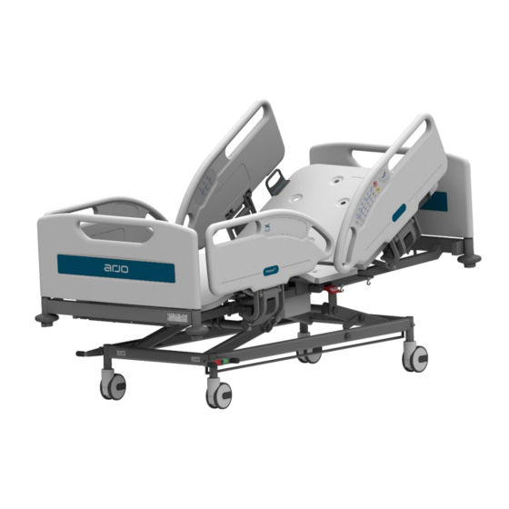
1. INTRODUCTION - Continued 1.2 Product Description The Arjo Prioma Medical Bed is an electrically operated acute care medical bed. The bed has multiple functions to provide bed nursing positions for both patient and carer. Scope This service manual covers all Arjo Prioma Medical Bed variants. - Page 7 1. INTRODUCTION - Continued Figure 1: Prioma Bed All power operated functions are operated by push button controls. Each function has separate up and down push buttons with the exception of electronic CPR and Trendelenburg functions with are a single touch control. Depending on the bed model, the patient can control the bed via a hand-held handset or by integrated controls on the inside face of the head end split side rails.
-
Page 8: Decontamination
2. DECONTAMINATION WARNING • Disconnect the bed from the mains power supply before carrying out cleaning procedures. • Do not allow the mains plug or power supply cord to get wet when cleaning the bed. • Disconnect the bed from the mains power supply before carrying out cleaning procedures. -
Page 9: Preventative Maintenance
The following preventative maintenance checks and procedures should be carried out every 12 months. All service and repair activities must only be carried out by properly qualified and trained persons approved by Arjo. Disposal of the product and its components should be compliant with local regulations. WARNING Before starting any maintenance activity, disconnect the bed from the mains power supply. -
Page 10: Battery Test
If the bed fails a second time, contact Arjo or an approved service agent. To maintain best performance, the backup battery should be replaced every four years by an approved service agent. -
Page 11: Handset Checks (If Fitted)
3 below. Preventative Maintenance Checks: Arjo recommends that the full check and testing regime is conducted between each bed use, or worst case during annual preventative maintenance. This should take no more than one (1) minute to complete. -
Page 12: Testing
4. TESTING The following serviceable tests should be performed before returning the bed to use after service, or if the function is suspect. These instructions should be read in conjunction with the instructions for use supplied with the product. If the result of any test is unsatisfactory, investigate and take the appropriate remedial action. -
Page 13: Manual Functions
4. TESTING - Continued Battery Operation. Check operation of the battery by completing the steps described in section Battery Test (refer to section 3) 4.3 Manual Functions The following tests check functions that are not electrically powered. Brakes & Steering. Check the brakes for efficient operation. -
Page 14: Troubleshooting
Connect the power cable to Power disconnected and a suitable mains power backup battery discharged. supply outlet All actuators inoperative Fuse blown and backup Call Arjo Service battery discharged. department Check all cable connections Roving handset, control between control units, panel or ACP disconnected. -
Page 15: Fault Indications
5. TROUBLE SHOOTING - (continued) 5.2 Fault Indications - Could be Flashing LEDs or Audible Warnings. The bed’s control software can detect and indicate faults with the electrical system by means of audible beeps and flashing LEDs. Audible Warnings. POSITION LOST on an actuator is indicated via an intermittent beep 200msec ON / 200msec off. -
Page 16: Servicing Instructions
Use only replacement parts that are approved by Arjo. Use only parts listed in this manual; similar parts from other Arjo products may not be compatible. If single use fasteners are removed, they should always be replaced with new parts. - Page 17 6. SERVICING INSTRUCTIONS - Continued All references to left or right of the bed are when viewed from the head end or by patient lying on the bed. Always refer to the appropriate diagram and parts list to identify component Part Numbers.
-
Page 18: Tools & Equipment
6. SERVICING INSTRUCTIONS - Continued Actuator Cable Clips Cable connections to actuators are held in place by retaining clips as shown in Figure 3. To release the clip, insert a small screwdriver through slot (A) on either side of the socket and press in the retaining lugs and pull the clip out (B). -
Page 19: Electrical Assembly
6. SERVICING INSTRUCTIONS - Continued 6.3 Electrical Assembly Figure 4: Electrical Assembly (including options) Page | 18 Commercial in confidence. User Manual Revision CTK-SM-REV8-060720... -
Page 20: Electrical Assembly Parts List
6. SERVICING INSTRUCTIONS - Continued 6.4 Electrical Assembly Parts List Item Part Number Description C0610022-00 C061 Control Box (if bed not fitted with ACP unit) C0615268-00 C061 Control Box (if fitted with ACP unit) 1015W1001-A Fixing Plate for Control Box 270439-00 LA27 Hi-Lo Actuator J18110... -
Page 21: Undercarriage Assembly
6. SERVICING INSTRUCTIONS - Continued 6.5 Undercarriage Assembly Part No. Description Unit 1677PJP125R05-9002 Tente 125mm Total Locking Castor 2076PJP125R26-28S45 Tente 125mm Single Central Locking Castor (Brake) 2074PJP125R26-28S45 Tente 125mm Single Central Locking Castor (Steer) 1946PJP125R26-28S45 Tente 125mm Twin Central Locking Castor (Brake) 1944PJP125R26-28S45 Tente 125mm Twin Central Locking Castor (Steer) 1946PJP150R26-28S45... -
Page 22: Crank & Crank Stabiliser Assemblies
6. SERVICING INSTRUCTIONS - Continued 6.6 Crank & Crank Stabiliser Assemblies Figure 6: Crank & Crank Stabiliser Assemblies Item Part Number Description G420-A2-3-2-Z-BE Crank Roller Bearing Spacer Bush S0000095 Crank Roller Bearing C380-3-6-Z-BE Crank to Deck Assembly Axle S0205016 M10 NYLOC Lock Nut C380-1-11-G M10 Plastic Nut Cover S0200032... -
Page 23: Base Frame/Mattress Platform Assembly
50 x 25 Plastic End Cap C380-CHXS-03Z ABS Thigh & Seat Section Cover G420-E3-5-ASM Head & Foot Panel Assembly (including infill) G420-E3-5-1 Arjo Blue Foot Panel Infill (with Arjo logo) G420-E3-5-2 Arjo Blue Foot Panel Infill (no logo) S0422001 Back Rest Rubber Stop C-T-0003-GR... -
Page 24: Backrest & Backrest Retraction Assemblies
6. SERVICING INSTRUCTIONS - Continued 6.8 Backrest & Backrest Retraction Assembly Figure 8: Backrest & Backrest Retraction Assemblies Item Part Number Description S0205016 M10 NYLOC Lock Nut S0108163 M10 x 55 Z/P Hex Head Bolt S0108956 M10 x 95 Z/P Hex Head Bolt C-4DL-QF-11-G-ASM Backrest Retraction Arm Assembly C380-10-9-G-ASM... -
Page 25: Thigh & Foot Section Assemblies
6. SERVICING INSTRUCTIONS - Continued 6.9 Thigh & Foot Section Assemblies Figure 9: Thigh & Foot Section Assemblies Item Part Number Description S0106009 M8 x 20 Z/P Hex Head Bolt S0205016 M10 NYLOC Lock Nut S0108163 M10 x 50 Z/P Hex Head Bolt C380-CHXS-03Z ABS Thigh &... -
Page 26: Base Extension & Linen Rack Assembly
6. SERVICING INSTRUCTIONS - Continued 6.10 Base Extension & Linen Rack Assemblies Figure 10: Base Extension & Linen Rack Assembly Item Part Number Description S0205016 M10 NYLOC Lock Nut S0200032 M10 x 45 Z/P Hex Head Bolt 805-16-Z-BE M5.5 x 60 Z/P Selock Pin 805-15-GR Plastic Head &... -
Page 27: Fold Down Tubular ¾ Rail Assembly
6. SERVICING INSTRUCTIONS - Continued 6.11 Fold Down Tubular ¾ Rail Assembly Figure 11: Fold Down Tubular ¾ Rail Assembly Item Part Number Description S0205016 M10 NYLOC Lock Nut 788-915-P-RD Rail Release Knob, Pin and Spring Kit 805-187 Male Plastic Rail Hinge 805-186 Female Plastic Rail Hinge S0108411... -
Page 28: Split Side Rails - Head End
6. SERVICING INSTRUCTIONS - Continued 6.12 Split Side Rails - Head End Figure 12: Split Side Rails – Head End Assembly Item Part Number Description 10ACK0172-B Nurse Control Panel Overlay (right hand) EU-02 HDPE Blow Moulded Head Panel (right hand) 10ACK0176 Patient Control Panel Overlay (right hand) STR09-0025... -
Page 29: Split Side Rails - Foot End Short
6. SERVICING INSTRUCTIONS - Continued 6.13 Split Side Rails - Foot End Short Figure 13: Split Side Rails – Foot End Short Assembly Item Part Number Description S0205016 M10 NYLOC Lock Nut S0205008 M10 x 60 Z/P Hex Head Bolt STR09-0025 Drop Down Split Rail Internal Plastic Cover EU-04... -
Page 30: Split Side Rails - Foot End Long
6. SERVICING INSTRUCTIONS - Continued 6.14 Split Side Rails - Foot End Long Figure 14: Split Side Rails – Foot End Long Assembly Item Part Number Description S0205016 M10 NYLOC Lock Nut S0205008 M10 x 60 Z/P Hex Head Bolt EU-02 HDPE Blow Moulded Head Panel (right hand) STR09-0025... -
Page 31: Brake / Steer Pedal Replacement
6. SERVICING INSTRUCTIONS - Continued 6.15 Brake / Steer Pedal Replacement (Refer Figure 5.) Removal: a) Raise the mattress platform to maximum height. b) Position the bed so that all the castors are lined up in the same direction and apply the brakes. -
Page 32: Battery Backup Replacement
6. SERVICING INSTRUCTIONS – Continued Head End Castor –Installation a) Before installing the braking / tracking castor, ensure that the castor is in neutral (free) mode. Insert the stem of the castor into the undercarriage wheel tube and align the retaining screw holes. Note: the tracking castor should be fitted at the right side, head end of the bed from the patient point of view. -
Page 33: Mains Power Cable Replacement
6. SERVICING INSTRUCTIONS - Continued 6.18 Mains Power Cable - Replacement (Refer Figure 4.) Removal a) Raise the mattress platform to maximum height and remove seat cover (figure 7 item 41). Unplug bed from mains power supply socket. b) Remove screw and star lock washer securing mains cable flying earth terminal to the bed frame. -
Page 34: Control Box Replacement
6. SERVICING INSTRUCTIONS - Continued 6.19 Control Box - Replacement (Refer Figure 4.) Removal a) Raise the mattress platform to maximum height and remove seat cover (figure 7 item 41). Unplug bed from mains power supply socket. Disconnect mains power cable replacement procedure –... -
Page 35: Junction Box / Underbed Light Replacement
6. SERVICING INSTRUCTIONS - Continued 6.20 Junction Box / Under Bed Light - Replacement (Refer Figure 4.) Removal a) Raise the mattress platform to the maximum height and remove seat cover (figure 7 item 41). Unplug the bed from mains power supply socket. b) Release junction box cable retainer (8) by inserting a small flat screwdriver into the slots on the front of the junction box to release the clips (A) (refer figure 18). -
Page 36: Roving Handset Replacement
6. SERVICING INSTRUCTIONS - Continued 6.21 Roving Handset - Replacement (Refer Figure 4.) Removal a) Raise the mattress platform to maximum height and remove seat cover (figure 7 item 41). Unplug the bed from mains power supply socket. b) Release junction box (8) cable retainer by inserting a small flat screwdriver into the slots (A) on the front of the junction box and pry off tabs (B) –... -
Page 37: Attendant Control Panel (Acom) Replacement
6. SERVICING INSTRUCTIONS - Continued 6.23 Attendant Control OpenBus Mini (ACOM) - Replacement (Figure 4.) Removal a) Raise the mattress platform to the maximum height and remove seat cover (figure 7 item 41). Unplug the bed from mains power supply socket. b) Release junction box (8) cable retainer by inserting a small flat screwdriver into the slots on the front of the junction box to release the clips refer section 19, figure 18. -
Page 38: Thigh Panel Actuator Replacement
6. SERVICING INSTRUCTIONS - Continued 6.25 Thigh Panel Actuator - Replacement (Refer figure 4) Removal a) Raise bed to the maximum height and if functional lower the knee break function to a flat position via handset. Disconnect bed from mains power supply. b) Remove seat top cover from bed frame (figure 7 item 41) in order to gain access to cable plug. -
Page 39: Actuator Cables Replacement
6. SERVICING INSTRUCTIONS - Continued Installation a) Apply grease to both pivot points prior to assembly. b) Position actuator, ensuring correct orientation and attach to bed frame using existing bolts and new Nyloc nuts (figure 7 items 27 & 39, figure 8 items 27 & 30). Be sure not to over tighten pivot bolts allowing actuator to pivot freely. -
Page 40: Cpr Handle & Cable Adjustment & Replacement
6. SERVICING INSTRUCTIONS - Continued 6.28 CPR Release Cable - Replacement & Adjustment (Refer figure 20) LH & RH side CPR release cable are of different length. Removal a) Raise the platform to maximum height and backrest to maximum elevation. Remove seat ABS cover (figure 7 item 41). -
Page 41: X-Ray Backrest Damper Replacement
6. SERVICING INSTRUCTIONS - Continued 6.30 X-Ray Backrest Damper - Replacement Removal a) Raise the bed and the backrest to their maximum heights. b) Remove the seat cover (figure 7 item 41). c) Remove retaining screw, washers and Nyloc nuts, and discard both nuts. Remove the damper. -
Page 42: Head-End Split Side Rail Replacement
6. SERVICING INSTRUCTIONS - Continued Installation a) Fit internal slide (62) and glide bushes (63) over base extension slide rails. b) Pop rivet internal slide fittings in place (60). c) Fit linen rack slide bushes x 4 each (61). d) Align base extension internal slides with mattress platform side tube and slide inside. -
Page 43: Fold-Down Tubular Side Rails Replacement
6. SERVICING INSTRUCTIONS - Continued 6.35 Fold Down Tubular Rails - Replacement (Refer figure 11) Removal WARNING Take care to avoid trapping fingers during the following procedure. a) Lock the side rail in the raised position. b) Remove four hexagon head bolts (70) and Nyloc nuts (27) securing both mounting brackets to bed frame, and discard Nyloc nuts. -
Page 44: Stabiliser Arm Replacement
6. SERVICING INSTRUCTIONS - Continued 6.38 Stabiliser Arm - Replacement (Refer figure 6) If both stabiliser arms need to be replaced, be sure to only replace one arm at a time, in order to maintain the positioning of the mattress platform. Removal a) Adjust the mattress platform to a mid-height position. -
Page 45: Mattress Platform Abs Covers Replacement
6. SERVICING INSTRUCTIONS - Continued Installation a) Fit two new roller bearings (25) and spacer bushes (24) onto the head end crank. b) Push the mattress platform assembly towards the foot end of the bed and lower it just enough to align the roller bearings (25) with the head end channels (figure 5 item 22) on the undercarriage frame. -
Page 46: Powder Coat Restoration
Damage to the paint finish on the frame or other components can be repaired by brush application of cellulose based paint obtainable from specialist paint suppliers or local distributors. To ensure colour match, contact Arjo quoting the serial number, for confirmation of finish colour. Procedure a) Clean and degrease the damaged area by wiping with a lint free cloth moistened with a suitable volatile solvent e.g. -
Page 47: Technical Data
7. TECHNICAL DATA 7.1 Product Specifications Dimensions Overall Length 219.5 cm Overall Length Base Extension Extended (28.5cm) 248.0 cm Bed Extension Length 28.5 cm Linen Rack (Bed Stripper) Extension 30.0 cm Mattress Surface Length - Between Panel Faces 203.0 cm Mattress Surface Length - Extended 231.5 cm Overall Width... -
Page 48: Environmental Protection
Incorrect disposal of this equipment and its component parts, particularly gas springs actuators, batteries and other electrical devices, may produce substances that are hazardous to the environment. To minimise these hazards, contact Arjo for information on correct disposal. 7.3 Symbols & Labels... -
Page 49: Product Lifetime
7. TECHNICAL DATA - Continued 7.4 Product Lifetime The lifetime of this equipment is typically (10) years. “Lifetime” is defined as the period during which the product will maintain the specified performance and safety, provided it has been maintained and operated in conditions of normal use in accordance with the requirements provided in the instructions for use manual 7.5 End of Life Disposal •... -
Page 50: Electromagnetic Compatibility
7. TECHNICAL DATA - Continued 7.7 Electromagnetic Compatibility EMC Test standard IEC60601-1-2:2014 – test result Classification of EUT: Group 1, Class B Test Item Standard Result IEC 60601-1-2:2014 Mains terminal disturbance voltage Reference: CISPR Pass 11:2009+A1:2010 IEC 60601-1-2:2014 Radiated emission Reference: CISPR Pass 11:2009+A1:2010... -
Page 51: Transportation & Storage
8. TRANSPORTATION AND STORAGE Handle with care. The Prioma bed should be stored in a clean, dry well ventilated area. Do not drop and avoid shock or violent impact when transporting. The following limits apply during transport and or a storage period of up to 6 weeks duration: Ambient temperature -15°C... -
Page 52: Regulatory Information
9. REGULATORY INFORMATION Caretek (China) Medical PLC Xiguakeng, Guanqiao Village, Shilou Town, Panyu District, Guangzhou City, Guangdong Province, P.R. China 511447 TEL: +8620-84846868 Shanghai International Holding Corp. GmbH (Europe) Eiffestrasse 80. D-20537 Hamburg, Germany Page | 51 Commercial in confidence. User Manual Revision CTK-SM-REV8-060720... - Page 53 Intentionally Left Blank Page | 52 Commercial in confidence. User Manual Revision CTK-SM-REV8-060720...
- Page 54 At Arjo, we are committed to improving the everyday lives of people affected by reduced mobility and age-related health challenges. With products and solutions that ensure ergonomic patient handling, personal hygiene, disinfection, diagnostics, and the effective prevention of pressure ulcers and venous thromboembolism, we help professionals across care environments to continually raise the standard of safe and dignified care.
Need help?
Do you have a question about the Prioma Series and is the answer not in the manual?
Questions and answers