Table of Contents
Advertisement
Advertisement
Table of Contents

Related Manuals for Arjo Enterprise 5000X


Summary of Contents for Arjo Enterprise 5000X
- Page 1 INSTRUCTIONS FOR USE Enterprise 5000X (E5X) 746-577-EN_16 • 0 /2019...
- Page 2 Mandatory to read the Instructions for Use Design Policy and Copyright ® and ™ are trademarks belonging to the Arjo group of companies. © Arjo 2019. As our policy is one of continuous improvement, we reserve the right to modify designs without prior notice.
-
Page 3: Table Of Contents
Contents Warnings, Cautions and Notes ............4 General Warnings ................4 1. Introduction ..............6 Product overview – Head Board On Mattress Platform ..... 8 Head Board On Base (Optional) ............8 Folding split side rails (Optional) ............. 10 2. Clinical Applications ............11 Intended use ................... -
Page 4: Warnings, Cautions And Notes
Unauthorised modifications or repairs to this product may affect its safety and will invalidate any warranty. Arjo accepts no liability for any incident, accident or reduction in performance that may occur as a result of such repairs or modifications. - Page 5 WARNING Always apply the brakes when the bed is stationary. To reduce the risk of injury due to falls, lower the bed to minimum height when the patient is unattended. Patients should not be left in the Trendelenburg position when unattended. To reduce the risk of overbalancing, do not allow the patient to get on or off the bed when the mattress platform is in a tilted (head down or foot down) position.
-
Page 6: Introduction
1. Introduction These instructions contain information for the installation, use and maintenance of the Arjo Enterprise® 5000X range of acute care hospital beds. These beds have multiple functions to provide the optimum nursing position for both patient and carer. Standard features... - Page 7 The model number and serial number can be found on the specification label; this is located on the bed frame below the head board. Specification label CAUTION Before using the bed, ensure that the “Power In” rating on the specification label is compatible with the local electricity supply.
-
Page 8: Product Overview - Head Board On Mattress Platform
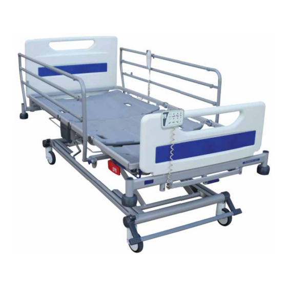
Product overview – Head Board On Mattress Platform A. Bedstripper (linen shelf) (Optional) L. Lifting pole socket B. Attendant Control Panel (ACP) M. Roller buffer C. Foot board N. Castor D. Calf extension sheet O. Drainage bag rail E. Calf section P. - Page 9 Head Board On Base (Optional) The bed can be optionally configured with the head board mounted on the base of the bed. The bed can also be configured with 3 or 5 bar easily removable side rails. The easily removable side rails are described more in section “To remove and install the 3 bar or 5 bar ¾...
-
Page 10: Folding Split Side Rails (Optional)
Folding split side rails (Optional) The bed can be optionally configured to use folding split side rails. In this configuration a side rail release lever is located directly below the side rail. The release lever is described more in section “To lower the folding split side rails:” in Chapter 4. A. -
Page 11: Clinical Applications
2. Clinical Applications WARNING To ensure the patient can use the bed safely, their age, size and condition should be assessed by a clinically qualified person. The use of head down tilt (Trendelenburg) or foot down tilt (reverse Trendelenburg) may be contraindicated for certain medical conditions. The tilt facility should only be used under the guidance of a clinically qualified person after assessment of the patient’s condition. -
Page 12: Contra-Indications
Contra- The maximum recommended patient weight is indications 185kg. The safe working load of the bed is 250kg. The safe working load is calculated as follows (in accordance with IEC 60601-2-52): Maximum patient weight 185kg Mattress 20kg Accessories (including attached loads) 45kg TOTAL 250kg... -
Page 13: Installation
3. Installation Connect the mains plug to a suitable socket outlet. Make sure the mains plug is easily accessible so it can be disconnected quickly in an emergency. When the bed is connected to the electricity supply, indicators will light on the control box (1) and Attendant Control Panel. - Page 14 WARNING If the power cord or mains plug is damaged, the complete assembly must be replaced by authorised service personnel. Do not remove the fitted plug, or use a rewireable plug or adapter. Make sure the power supply cord is not stretched, kinked or crushed. Do not allow the power supply cord to trail on the floor where it may cause a trip hazard.
-
Page 15: Mattresses
Mattresses WARNING Always use a mattress of the correct size and type. Incompatible mattresses can create hazards. Entrapment hazards may exist when using a very soft mattress, even if it is the correct size. The maximum recommended mattress thickness for use with side rails is 18cm. Read the instructions for use supplied with the mattress. - Page 16 Compliance with this standard when using other mattresses must be validated by the user. For more information on suitable mattresses and mattress replacements, contact your local Arjo office or approved distributor. A list of Arjo offices can be found at the back of this manual.
-
Page 17: Operation
4. Operation WARNING Operate the brake pedals with your feet while wearing suitable shoes. Do not operate the pedals with your hands. Brakes and The brake pedals at the foot end of the bed have three positions as shown: steering BRAKE: brakes are applied on all four castors. -
Page 18: Foot Pedal For Adjustment Of Bed Height (Optional)
Brake bar The brake pedals may be linked by a full width brake bar (1) which (Optional) makes it easier to operate the pedals. Brake bar Head end brake Brake pedals are provided at the head end of the bed. These operate in pedals the same way as the foot end pedals. -
Page 19: How To Use The 5Th Wheel (Optional)
How to use the 5th Wheel (Optional) The 5th wheel provides improved mobility and steering. Activate 5th Wheel: 1. Step down on the head end of the 5th wheel activation pedal (A). (See Fig. 1) The 5th wheel (B) will lower until it has contact with the floor. 2. -
Page 20: Side Rails (Optional)
When using removable ¾ length side rails, do not fit different side rails to those originally supplied by Arjo with the bed. Make sure the serial number label on the side rail corresponds to the serial number on the bed – refer to page 7 for a description of the bed serial number. - Page 21 To lower the ¾ length folding side rail: Hold the top rail (1) just behind the hinge. Pull the blue operating knob (2) and lower the side rail towards the foot end of the bed (3). ¾ length folding side rail operation To raise the side rail: Hold the top rail (1) just behind the hinge.
- Page 22 To remove and install the 3 bar or 5 bar ¾ length folding side rail: Some beds are fitted with easy to remove folding side rails. Removable folding side rails are available in 3 bar or 5 bar configurations. Removable side rails are identical in operation to the fixed ¾...
- Page 23 To lower the folding split side rails: Hold either side rail handle (1). Pull the release lever (2) and lower the side rail (3) so that it folds down below the mattress platform. Folding split side rail operation To raise the side rail: Hold either side rail handle (1).
-
Page 24: Cpr Backrest Release
Manual CPR release handles are located below the calf section on either CPR backrest side of the bed. release If the patient suffers a cardiac arrest, pull the CPR release handle (1). This will lower the backrest to enable cardio-pulmonary resuscitation to be carried out. -
Page 25: X-Ray Cassette Tray (Optional)
The X-ray cassette tray allows thoracic X-ray photography with the X-ray cassette backrest at any angle and without the patient moving from the bed. tray (Optional) WARNING Position the mattress platform at an ergonomic height to allow easy loading and removal of X-ray cassettes. - Page 26 Release the knob to hold the tray in the fully open position (3). Position the X-ray cassette (4) on the tray with its bottom edge against the lip at the foot end of the tray. Positioning the X-ray cassette Pull the knob and slide the tray underneath the backrest. The red moulding on the top of the X-Ray sitting tool indicates the top right hand corner of the X-Ray cassette.
-
Page 27: Bed Length Adjustment
The length of the bed is adjustable to three set positions. These are Bed length typically used as follows: adjustment Short, for manoeuvring the bed in confined spaces Standard length, for normal use Extended, to accommodate very tall patients WARNING Install a suitable foam mattress extension (squab) at the head end when the bed is extended. - Page 28 To extend the mattress platform: Lift the blue extension catch bar (1). Hold the middle of the end crossbar (2) and pull out the mattress platform to the required position. Release the catch bar. Extending the mattress platform To shorten the bed: Reverse the above procedure.
-
Page 29: Bedstripper (Linen Shelf) (Optional)
The bedstripper is used for supporting clean linen when the bed sheets Bedstripper are being changed. (linen shelf) (Optional) Pull out the bedstripper from its closed position below the foot board. After use, push the bedstripper back to its closed position. Bedstripper (linen shelf) CAUTION The safe working load of the bedstripper is 20kg. -
Page 30: Lifting Pole And Accessory Sockets
Lifting pole sockets (1) are located at the head end of the mattress Lifting pole platform. and accessory sockets Sockets to support compatible accessories are located at the head end (2) and foot end (3) of the bed. Lifting pole and accessory sockets (head end) Accessory sockets (foot end) -
Page 31: Drainage Bag Rails
Rails (1) to support drainage bags, etc. are located below the thigh and Drainage bag backrest sections on either side of the bed. rails (Optional) The bed may also be fitted with DIN accessory rails (2). Drainage bag rails and DIN rail CAUTION The maximum weight that can be safely supported by each drainage bag rail and DIN rail is 5kg. -
Page 32: Mattress Platform Sections
As standard the bed is supplied with curved platform sections. Optional Mattress flat platform sections are available. platform sections The four mattress platform sections (backrest, seat, thigh and calf) can be removed by pulling them upwards off the mattress platform frame. Lift off the calf extension sheet (1) before removing the calf section (2). - Page 33 Adjusting the mattress platform The bed is provided with two control handsets: a patient handset with basic controls only and a more comprehensive attendant control panel (ACP) for use by the carer. The functions on both handsets are described separately over the next few pages. To adjust the mattress platform: press and hold the appropriate button until the required position is achieved.
-
Page 34: Patient Handset
Patient handset The patient handset can be positioned on either side of the bed. WARNING Store the handset on the side rail using the clip on the back; this will help to prevent accidental operation of the controls. The patient should be shown how to use the handset by the carer. Patient handset NOTE On some models the patient handset does not have mattress platform height, backrest or... - Page 35 Bio-Contour The Bio-Contour up button simultaneously raises the backrest and thigh sections to provide upright patient profiling; the raised thigh section prevents the patient sliding down the bed. The Bio-Contour down button returns the mattress platform to a flat position. Backrest angle (Optional) These buttons raise and lower the backrest.
-
Page 36: Attendant Control Panel (Acp)
Attendant Control Panel (ACP) The ACP is located at the foot end of the bed. WARNING The ACP must be kept out of the reach of the patient. Attendant Control Panel (ACP) Power on indicator - lights when the bed is connected to the electricity supply Battery indicator - refer to the section Backup battery. - Page 37 Thigh section These buttons raise and lower the thigh section. When the thigh section is first raised from the flat position, the calf section will be in the Fowler position (angled downwards). To change the calf section to the vascular (horizontal) position, refer to the section Adjusting the calf position.
-
Page 38: Adjusting The Calf Position
Adjusting the calf position When the thigh section is raised, the calf section can be manually changed to the vascular (horizontal) position: Hold the side of the calf section frame. Lift the calf section upwards until it latches. Changing from Fowler position (left) to vascular To return the calf section to the Fowler position: Use the patient handset or ACP to lower the thigh section to the flat position;... -
Page 39: Function Lockout
Function lockout Function lockout can be used to prevent operation of the controls, e.g. when inadvertent movement of the mattress platform could injure the patient. The indicator above each function shows its status: on = function locked; off = function unlocked. To lock (prevent) ALL functions: press and hold the Function Lock button for five seconds. -
Page 40: Backup Battery
Backup battery CAUTION To ensure the battery is kept fully charged and prevent damage to the battery, the bed should be connected to the electricity supply at all times during normal use. The battery is intended for occasional short term use. Its life will be reduced if it is used to power the bed for long periods. -
Page 41: Duty Cycle Lockout
Recharging the To recharge the battery, connect the bed to the electricity supply. Allow at backup battery least eight hours to recharge the battery when it is completely discharged. While the battery is recharging, the ACP battery indicator lights yellow. The indicator will go out when the battery is fully charged. -
Page 42: Product Care
5. Product Care WARNING Disconnect the bed from the electricity supply before starting any cleaning or maintenance activity. The bed will still operate on battery power if the function has not been locked on the ACP. Decontamination WARNING Do not allow the mains plug or power supply cord to get wet. NOTE These instructions also apply to accessories but not to mattresses or side rail pads. - Page 43 Many other disinfectants are used in healthcare facilities, and it is not possible for Arjo to test each one to determine whether it may affect the appearance or performance of the bed.
-
Page 44: Preventive Maintenance
Check for correct fitting of the locking pin on 3 bar and 5 bar removable side rails Check operation of manual CPR release handles on both sides of the bed If the result of any of these tests is unsatisfactory, contact Arjo or an approved service agent. - Page 45 WARNING The procedures below must be carried out by suitably trained and qualified personnel. Failure to do so may result in injury or an unsafe product. Actions to be done by qualified personnel Yearly Carry out a full test of all electrical bed positioning functions (backrest, height, tilt, etc.) Check that the bedstripper / linen shelf remains in its closed position when maximum foot down tilt is applied.
-
Page 46: Battery Test
If this test is not completed successfully, connect the bed to the electricity supply for at least eight hours to recharge the battery then perform the test again. If the bed fails a second time, contact Arjo or an approved service agent. -
Page 47: Troubleshooting
Troubleshooting If the equipment fails to operate correctly, the table below suggests some simple checks and corrective actions. If these steps fail to resolve the problem, contact Arjo or an approved service agent. Symptom Possible cause Action “Beeping” sound when... -
Page 48: Fault Indications
Fault indications The bed’s control software indicates problems in the electrical system by means of flashing indicators on the Attendant Control Panel (ACP). If you experience any of the indications below, contact Arjo or an approved service agent. Indication Possible cause... -
Page 49: Accessories And Cables
6. Accessories and Cables Recommended accessories for the Enterprise 5000X range are shown in the table below. Note that some items may not be available in all countries. Accessory Product Code Lifting pole with strap and handle ENT-ACC01 IV pole... -
Page 50: Technical Data
7. Technical Data General Safe working load 250kg Maximum patient weight 185kg Product weight 144kg approx. Audible noise 50dB approx. Operating conditions Temperature 10 C to 40 C Relative humidity 20% to 90% at 30 C, non-condensing Atmospheric pressure 700hPa to 1060hPa Electrical data Power input 1.6A max. - Page 51 In-bed length Position 1 (Short) 192cm Position 2 (Standard) 203cm Position 3 (Extended) 215cm Overall width 103cm Height of mattress platform (centre of seat section to floor) With 125mm castors 32cm to 76cm With 150mm castors 34cm to 78cm Head down tilt angle 12°...
- Page 52 Symbols Safe working load Maximum patient weight Alternating current (a.c.) Caution Refer to instructions for use Type B applied part. Applied parts are considered to be: Upper frame section, Bed controls, Side Rails, Head and Foot Boards Manufacturer / date of manufacture CE marking indicating conformity with European Community harmonised legislation Waste Electrical and Electronic Equipment (WEEE) - do not...
- Page 53 Recommended mattress size Recommended patient size Total weight of the equipment including its safe working load Calf section vascular position Mattress platform extension Do not install side rails on the bed Mandatory to read instructions for use Indicates the product is a Medical Device according to EU Medical Device Regulation 2017/745...
-
Page 54: Warranty And Service
For service, maintenance and any questions regarding this product, please contact your local Arjo office or approved distributor. A list of Arjo offices can be found at the back of this manual. Have the model number and serial number of the equipment to hand when contacting Arjo... -
Page 55: Electromagnetic Compatibility
EMI (electromagnetic interference) from external sources. Some procedures can help reduce electromagnetic interferences: • Use only Arjo cables and spare parts to avoid increased emissions or decreased immunity which can compromise the correct functioning of the equipment. • Ensure that other devices in patient-monitoring and/or life-support areas comply to accepted emissions standards. - Page 56 Guidance and manufacturer’s declaration – electromagnetic immunity IEC 60601-1-2 Electromagnetic environment - Immunity test Compliance level test level guidance ±2kV, ±4kV, ±2kV, ±4kV, ±8kV, Floors should be wood, concrete Electrostatic ±8kV, ±15kV ±15kV air or ceramic tile. If floors are discharge (ESD) covered with synthetic material EN 61000-4-2...
- Page 57 Guidance and manufacturer’s declaration – electromagnetic immunity IEC 60601-1-2 Electromagnetic environment - Immunity test Compliance level test level guidance Power Power frequency magnetic fields frequency 30A/m 30A/m should be at levels characteristic Magnetic field of a typical location in a typical 50 Hz or 60 Hz 50 Hz commercial or hospital...
- Page 58 Intentionally left blank...
- Page 59 AUSTRALIA FRANCE POLSKA Arjo Australia Pty Ltd Arjo SAS Arjo Polska Sp. z o.o. 78, Forsyth Street 2 Avenue Alcide de Gasperi ul. Ks Piotra Wawrzyniaka 2 O’Connor CS 70133 PL-62-052 KOMORNIKI (Pozna ) AU-6163 Western Australia FR-59436 RONCQ CEDEX...
- Page 60 At Arjo, we are committed to improving the everyday lives of people affected by reduced mobility and age-related health challenges. With products and solutions that ensure ergonomic patient handling, personal hygiene, disinfection, diagnostics, and the effective prevention of pressure ulcers and venous thromboembolism, we help professionals across care environments to continually raise...
Need help?
Do you have a question about the Enterprise 5000X and is the answer not in the manual?
Questions and answers