
Related Manuals for Lanner NCR-1510


Summary of Contents for Lanner NCR-1510
- Page 1 Network Appliance Platform Hardware Platforms for Network Computing NCR-1510 User Manual Version: 1.0 Date of Release:2020-06-23...
- Page 2 - assumed to be qualified in the servicing of computer equipment, such as professional system integrators, or service personnel and technicians. The latest version of this document can be found on Lanner’s official website, available either through the product page or through the...
- Page 3 Lanner Q&A page for diagnostic procedures and troubleshooting steps. Technical Support In addition to contacting your distributor or sales representative, you could submit a request to our Lanner Technical Support at http://www.lannerinc.com/technical-support where you can fill in a support ticket to our technical support department.
- Page 4 Contact Information Taiwan Corporate Headquarters China Lanner Electronics Inc. Beijing L&S Lancom Platform Tech. Co., Ltd. 7F, No.173, Sec.2, Datong Rd. Xizhi District, Guodong LOFT 9 Layer No. 9 Huinan Road, New Taipei City 22184, Taiwan Huilongguan Town, Changping District, Beijing...
- Page 5 Statement This equipment has been tested and found to comply with the limits for a Class A digital device, pursuant to Part 15 of FCC Rules. These limits are designed to provide reasonable protection against harmful interference in a residential installation. This equipment generates, uses and can radiate radio frequency energy and, if not installed and used in accordance with the instruction, may cause harmful interference to radio communications.
- Page 6 Safety Guidelines Follow these guidelines to ensure general safety: Keep the chassis area clear and dust-free during and after installation. Do not wear loose clothing or jewelry that could get caught in the chassis. Fasten your tie or scarf and roll up your sleeves.
- Page 7 A battery subjected to extremely low air pressure may result in an explosion or the leakage of flammable liquid or gas. Avertissement concernant la pile au lithium Risque d’explosion si la pile est remplacée par une autre d’un mauvais type. Jetez les piles usagées conformément aux instructions.
- Page 8 The installation of this product must be performed by trained specialists; otherwise, a non-specialist might create the risk of the system’s falling to the ground or other damages. Lanner Electronics Inc. shall not be held liable for any losses resulting from insufficient strength for supporting the system or use of inappropriate installation components.
- Page 9 Electrical Safety Instructions Before turning on the device, ground the grounding cable of the equipment. Proper grounding (grounding) is very important to protect the equipment against the harmful effects of external noise and to reduce the risk of electrocution in the event of a lightning strike. To uninstall the equipment, disconnect the ground wire after turning off the power.
-
Page 10: Table Of Contents
Table of Contents Chapter 1: Product Overview ............11 Package Content ......................... 11 Optional Kits ..........................11 Ordering Information ......................... 11 System Specifications ......................... 12 Front Panel ..........................13 Rear Panel ........................... 14 Side Panel ........................... 15 Chapter 2: Motherboard Information ..........16 Block Diagram .......................... -
Page 11: Chapter 1: Product Overview
CHAPTER 1: PRODUCT OVERVIEW NCR-1510 is a wide-temperature fanless network appliance optimized for SD-WAN or uCPE. This new offering will allow service providers to deploy the SD-WAN services in demanding environment and critical infrastructure. Powered by Intel® Atom® C3000 (codenamed Denverton) CPU, the NCR-1510 features solid performance and Intel’s QuickAssist Technology running up to 10Gbps, offering cryptographic acceleration... -
Page 12: System Specifications
System Specifications Form Factor Desktop Intel® Atom® C3308/C3508/C3708 Processor Options (Denverton) Platform CPU Socket Onboard Chipset Security Acceleration Intel® QuickAssist Technology BIOS AMI SPI Flash BIOS Technology DDR4 up to 2400MHz ECC/non-ECC DIMM System Memory Max. Capacity SKU A: 8GB, SKU B/C:16GB Socket 1x or 2x 260-pin SODIMM 4x GbE RJ45 Intel®... -
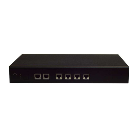
Page 13: Front Panel
Front Panel (NCR-1510A/B/C) NCR-1510A NCR-1510B NCR-1510C F2 F5 Description Console Port 1x Mini USB Console Port LED Indicator Power Status/System Status/Storage Activity 6x 10/100/1000Mbps Ethernet ports GbE Port 4x 10/100/1000Mbps Ethernet ports SFP Port 2x SFP Port with LED Indicator USB Port 2x USB 3.0 Port (SKU B/C) - Page 14 Front Panel (NCR-1510D/E/F) NCR-1510D NCR-1510E NCR-1510F Description Console Port 1x Mini USB Console Port LED Indicator Power Status/System Status/Storage Activity 6x 10/100/1000Mbps Ethernet ports GbE Port 4x 10/100/1000Mbps Ethernet ports SFP Port 2x SFP Port with LED Indicator USB Port 2x USB 3.0 Port (SKU B/C) SIM Slot 1x PGN Module Slot...
-
Page 15: Rear Panel
Rear Panel Description Power Switch 1x Power Button Reset Button For software reset DC Jack 1x DC Power Jack Antenna Port 4x Reserved antenna port for Wi-Fi / LTE module Side Panel Description SIM Slot 1x SIM Slot for accommodation of 2x Nano SIM... -
Page 16: Chapter 2: Motherboard Information
CHAPTER 2: MOTHERBOARD INFORMATION Block Diagram The block diagram indicates how data flows among components on the motherboard. Please refer to the following figure for your motherboard’s layout design. -
Page 17: Motherboard Layout
Motherboard Layout This layout shows the connectors and jumpers on the board, as a reference of the pin assignments and the internal connectors. RST1 PWR1 SIM1 JRESET1 SIM2 MPCIE1 SIM3 DIMM 2 CON1 DIMM 1 MPCIE2 SATA MIO1 80Port1 CON1 USB2 BAT3 SPI1... -
Page 18: Chapter 3: Hardware Setup
CHAPTER 3: HARDWARE SETUP To reduce the risk of personal injury, electric shock, or damage to the system, please remove all power connections to shut down the device completely. Also, please wear ESD protection gloves when conducting the steps in this chapter Opening the Chassis Wall Mounting The system can be mounted on a flat surfaced wall. -
Page 19: Dc Power Supply Installation
On the wall, measure the exact place where you want to hang the system, and drill four holes that match the four mounting holes on both brackets. Insert four anchoring bolts into the holes. Align the four mounting holes on the system’s brackets with the four anchoring bolts you just installed on the wall. - Page 20 Remove Partition Please remove the partition board on top of the motherboard to install key parts and SSD drive. First, disconnect the Power Cable and USB/2-Pin cable (Sku D/E/F) before you do so. Then remove the eight screws on the partition. Unmount the partition by tilting it a bit and sliding it out.
- Page 21 Installing System Memory The motherboard supports DDR4 registered DIMM memory for heavy-duty operations. Please follow the steps below to install the DIMM memory modules. Locate the memory slots on the motherboard Memory Slots Align the notch of the module with the socket key in the slot. Tilt the end of the golden fingers down while carefully inserting the card into the slot.
- Page 22 Installing Mini PCI-E Module Locate the Mini PCI-E module slot on the motherboard. Mini PCI-E Mini PCI-E Align the notch of the module with the socket key in the slot. Tilt the end of the golden fingers down while carefully inserting the card into the slot. Press vertically on the other end of the card until it clicks into place.
- Page 23 Installing M.2 Module Locate the M.2 module slot on the motherboard. M.2 Module 2. Align the notch of the module with the socket key in the slot. Tilt the end of the golden fingers down while carefully inserting the card into the slot. 3.
- Page 24 Installing 2.5” Hard Disk Mount your SSD drive on the partition BEFORE you mount it on top of the motherboard. Locate the SSD drive slot on the partition 2.5” SSD/HDD Slot Connect the SATA cable to the hard disk. SATA Port Mount the disk onto the empty partition with the provided disk screws.
- Page 25 Mounting the partition* and your drive back to the device. Plug the data/power connector of the SATA cable into the corresponding port on the motherboard. SATA Power Connector SATA Data Connector *Note: As you need to mount the partition on the motherboard, please make sure you have installed all key parts you needs on the motherboard before you do so.
- Page 26 PGN Module Installation Installing the PGN Module Remove the front panel and slide in the PNG Module Installing the SIM Card 1. Slide the SIM card holder to the open position, and then carefully lift it up. 2. Insert the SIM card with the gold metal side facing outwards as shown in the picture. 3.
- Page 27 This product is intended to be supplied by a listed power adapter or DC power source, rated 9-54Vdc, 7.8-1.3A minimum, Tma = 70 degree C, and the altitude of operation = 5000m. If you need further assistance with purchasing the power source, please contact to Lanner Electronics Inc. for further information.
-
Page 28: Appendix A: Led Indicator Explanations
APPENDIX A: LED INDICATOR EXPLANATIONS The status explanations of LED indicators on the Front Panel are as follows: Power Status System Status HDD Activity System Power Green The system is powered and running The system is powered off System Status This LED indicator is programmable. -
Page 29: Appendix B: Terms And Conditions
APPENDIX B: TERMS AND CONDITIONS Warranty Policy 1. All products are under warranty against defects in materials and workmanship for a period of one year from the date of purchase. 2. The buyer will bear the return freight charges for goods returned for repair within the warranty period; whereas the manufacturer will bear the after service freight charges for goods returned to the user. -
Page 30: Rma Service Request Form
RMA Service Request Form When requesting RMA service, please fill out the following form. Without this form enclosed, your RMA cannot be processed.
Need help?
Do you have a question about the NCR-1510 and is the answer not in the manual?
Questions and answers