Table of Contents
Advertisement
Quick Links
I N S T A L L A T I O N I N S T R U C T I O N S
This device complies with part 15 of the FCC rules. Operation is subject to the following 2 conditions: (1) This device may not cause harmful interference, and (2) this
device must accept any interference received, including interference that may cause undesired operation.
This equipment has been tested and found to comply with the limits of a Class B digital device, pursuant to Part 15 of the FCC rules. These limits are designed to
provide reasonable protection against harmful interference in a residential installation. This equipment generates, uses and can radiate radio frequency energy, and if
not installed and used in accordance with the instructions, may cause harmful interference to radio or television communications. However, there is no guarantee that
the interference will not occur in a particular installation. If this equipment does cause harmful interference to radio or television reception, which can be determined by
turning the equipment off and on, the user is encouraged to try to correct the interference by one of the following measures:
•
Reorient or relocate the receiving antenna
•
Increase the separation between the equipment and receiver
•
Connect the equipment to an outlet on a circuit other than that to which the receiver is connected
Consult the dealer or an experienced radio/TV technician for help.
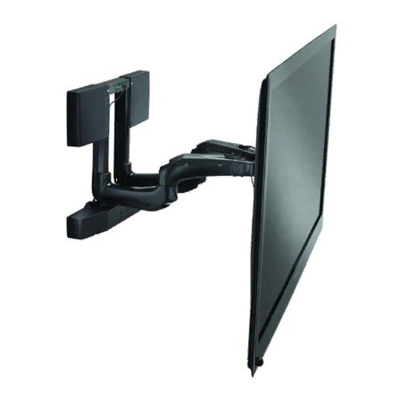
Automated Wall Mount
PXR
Advertisement
Table of Contents

Subscribe to Our Youtube Channel
Related Manuals for CHIEF PXR


Summary of Contents for CHIEF PXR
- Page 1 I N S T A L L A T I O N I N S T R U C T I O N S Automated Wall Mount This device complies with part 15 of the FCC rules. Operation is subject to the following 2 conditions: (1) This device may not cause harmful interference, and (2) this device must accept any interference received, including interference that may cause undesired operation.
-
Page 2: Disclaimer
It is the installer’s responsibility to make sure the weight of all components attached to the PXR does not exceed 150 lbs READ ALL INSTRUCTIONS BEFORE USING THIS (68.0 kg). -
Page 3: Table Of Contents
In-Wall Box Trim Installation (Optional) 13 Arm Engagement 13 Installing IR Sensor 14 Attaching Interface Brackets to Display 15 Hanging Display on PXR 16 Cable Management 16 Final Attachment to Wall Mounting Bracket 18 SET-UP AND CONFIGURATION 18 Running LEARN MODE 19... -
Page 4: Dimensions
Installation Instructions DIMENSIONS 20.45 BACK 519.5 6.36 5.47 17.44 442.9 8.06 9.19 233.4 CENTER OF INTERFACE TO MOUNTING HOLES 45° PAN LEFT 45° PAN RIGHT .739 4.75 18.8 120.6 12.7 16.00 L/R SHIFT 406.4 26.96 684.7 MAX. DISTANCE 4.50 FROM WALL 114.3 29.25 MIN. -
Page 5: Legend
Installation Instructions LEGEND Tighten Fastener Pencil Mark Apretar elemento de fijación Marcar con lápiz Befestigungsteil festziehen Stiftmarkierung Apertar fixador Marcar com lápis Serrare il fissaggio Segno a matita Bevestiging vastdraaien Potloodmerkteken Serrez les fixations Marquage au crayon Loosen Fastener Drill Hole Aflojar elemento de fijación Perforar Befestigungsteil lösen... -
Page 6: Tools Required For Installation
D (6) F (6) M5 x 20mm M5 x 16mm M5 x 25mm Q (1) H (6) G (6) [PXR] M6 x 25mm M6 x 16mm I (6) K (4) J (6) M8 x 50mm M8 x 20mm M8 x 30mm... -
Page 7: Site Preparation
One possible electrical Locating and Preparing a Mounting Site outlet location The PXR was designed to be installed onto a 16" on center 2" x 4" wood stud or solid concrete wall; or into the PAC-502 in-wall box (not included). -
Page 8: Pxr Diagram
PXR!! NEVER use the PXR as a vertical lift! ONLY operate the PXR when securely mounted in a vertical position! center NEVER operate the PXR while it is lying down or tilting back! of display IMPORTANT ! : When considering the PXR location,... - Page 9 (view from below) (RB) x 2 (RC) x 2 Figure 5 Lower PXR (Q) onto mounting bracket (X), ensuring PXR Figure 6 fits over mounting bracket tabs. (See Figure 6) Mark the pilot holes through PXR upper bracket. (See Figure 7) (RB) x 2 Carefully remove the PXR from the mounting bracket.
-
Page 10: Installing To A Solid Concrete Wall
11. Connect and route power cord (Z) through PXR cable management areas. (See Figure 8) Lowest edge IMPORTANT ! : Do not power the PXR until it is ready to of PXR be tested. See Set-Up and Configuration section. center of display 9.19"... - Page 11 (See Figure 13) any wall covering until flush with the concrete wall. (See Figure 10) IMPORTANT ! : Do not power the PXR until it is ready to be tested. See Set-Up and Configuration section. 13. Return PXR to mounting bracket.
-
Page 12: Installing In An In-Wall Box
OR DAMAGE TO EQUIPMENT! DO NOT deviate from installation instructions provided. DO NOT substitute hardware. Align mounting holes at top of PXR with two mounting holes in PAC502. (See Figure 14) Figure 16 Remove and save two screws from lower cover. (See Figure 17) Remove and save lower cover. -
Page 13: In-Wall Box Trim Installation (Optional)
10. Secure bottom of PXR in PAC502 using fasteners supplied with PAC502. NOTE: If the PXR is installed in an in-wall box, proceed to Step 2. 11. Replace lower cover and secure with two Phillips head Carefully remove hook and loop straps from each PXR arm. -
Page 14: Installing Ir Sensor
Installation Instructions Open cable management covers on bottom of PXR arms. Engage PXR arms by lining up pin with opening and using CAUTION: PXR SHOULD ONLY BE MOVED USING 9" hex head wrench (Y) in opening on bottom of each arm. -
Page 15: Attaching Interface Brackets To Display
Select correct screws, spacers (if necessary) and universal interface brackets are furthest protrusion from back of PXR. washers from the hardware bag (A-N) and attach brackets (See Figure 24) (V) to back of display. -
Page 16: Hanging Display On Pxr
Lock display with attached interface brackets to PXR using two bracket locks (W) and four 1/4-20 x 1" hex head cap screws Hang display onto the PXR, ensuring that top hooks of (U). (See Figure 25) and (See Figure 27) interface brackets (V) are hooked over the PXR top rail. - Page 17 Close cable management covers, being careful to not pinch cables under covers. (See Figure 31) signal cables in separate PXR arms. Open cable management covers on top of both PXR arms. (See Figure 28) and (See Figure 29) Figure 29 Extend cables from display and lay cables within top of arms.
-
Page 18: Final Attachment To Wall Mounting Bracket
Installation Instructions If necessary, use cable management flap on PXR base to route cables from left arm to PXR right side. (See Figure 28) WARNING: If the display is changed, cables are re-routed, and (See Figure 33) or an accessory is added/removed, it is best to recalibrate the PXR by going through the learn mode sequence. -
Page 19: Running Learn Mode
Installation Instructions Running LEARN MODE Plug power cord (Z) into PXR and into the nearest power source. HOME SAVE NOTE: Once power is applied to the unit, the indicator lights will flash 5 times. This indicates the unit needs to be calibrated to your specific screen. -
Page 20: Saving A Preset
[IV]. changed. Determine what address is not used by another Chief automated product. Using the DIP switches on the I/O interface (See Figure 38), set the PXR to one of the unused addresses. (See Figure 39) -
Page 21: Rs-485 Commands
Figure 39 1. Blank 2. TDA (-) If the address of the PXR is changed, the remote control and any RS-485 commands will also need to be changed to 3. TDB (+) match it. See the Advanced Programming document for 4. -
Page 22: Fault Conditions
In order to move the PXR incrementally, the remote control main control board (visible through the control housing). (See must be used. The only way to move the PXR with RS-485 is by Table 1) A red light will flash the same code on the I/O board. - Page 23 Installation Instructions...
- Page 24 Europe A Fellenoord 130 5611 ZB EINDHOVEN, The Netherlands P +31 (0)40 2668620 F +31 (0)40 2668615 Chief Manufacturing, a products division Asia Pacific A Office No. 1 on 12/F, Shatin Galleria of Milestone AV Technologies 18-24 Shan Mei Street...
Need help?
Do you have a question about the PXR and is the answer not in the manual?
Questions and answers