CHIEF PNR Installation Instructions Manual
Large flat panel dual arm wall mount
Hide thumbs
Also See for PNR:
- Installation instructions manual (12 pages) ,
- Specification sheet (1 page)
Table of Contents
Advertisement
Quick Links
I N S T A L L A T I O N I N S T R U C T I O N S
Large Flat Panel
Dual Arm Wall Mount
Model PNR™
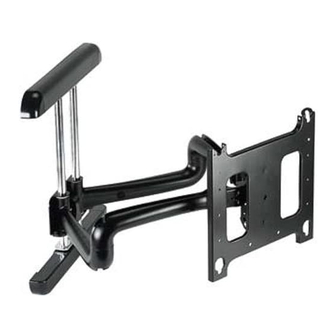
The PNR is wall-mounted, rugged, versatile, and
installer-friendly. The PNR is compatible with the
standard (14" x 14") PSB interface bracket in which a
display can be mounted in either the landscape or
portrait position on the PNR.
The dual arms on the PNR:
•
Extend from the wall 24-7/8" in length
•
Pivot up to 90º left or right of center
The standard PNR is shipped with the support posts for
the dual arms centered in the mount. The support posts
can be moved laterally right or left of center to readily
accommodate sites with limited wall space. The mount
also has two inches of height adjustment. The tilt range
for the display is 5º up and 15º down.
The PNR was designed for fast installation. After drawing
the plumb line and installing the two top lag bolts into the
dual wall studs, the installer hangs the PNR on its top
bracket and installs two lag bolts in the bottom bracket.
Next, the installer makes the height adjustment, mounts
the display, and connects the power/audio/video cables,
which are diverted into the built-in path in the swing-out
arms. After making the lateral, rotational, and tilt
adjustments, the installation process is complete.
BEFORE YOU BEGIN
CAUTION: To prevent damage to the PNR, which could affect or void the Factory warranty, and to the equipment that
will be attached to it, thoroughly study all instructions and illustrations before you begin the installation. Pay particular
attention to the "Important Warnings and Cautions" on Page 2.
•
The combined weight of the components installed on the PNR must not exceed 200 lbs. (90.72kg).
•
The PNR wall mount must be installed on dual wall studs or supporting framework. The wall to which the PNR is
anchored must be capable of supporting five times the total weight of the mount and all attached equipment.
•
If you have any questions about this installation, contact Chief Manufacturing at 1-800-582-6480.
CHIEF MANUFACTURING INC.
1-800-582-6480 952-894-6280 FAX 952-894-6918
8401 EAGLE CREEK PARKWAY, STE 700
SAVAGE, MINNESOTA 55378 USA
8831-000007 Rev E
©2006 Chief Manufacturing
www.chiefmfg.com
02/06
Advertisement
Table of Contents

Related Manuals for CHIEF PNR


Summary of Contents for CHIEF PNR
- Page 1 • The PNR wall mount must be installed on dual wall studs or supporting framework. The wall to which the PNR is anchored must be capable of supporting five times the total weight of the mount and all attached equipment.
-
Page 2: Table Of Contents
WARNING: Be aware also of the potential for personal injury or damage to the unit if it is not adequately mounted. WARNING: The installer is responsible for verifying that the wall to which the PNR is anchored will safely support the combined load of all attached components or other equipment. - Page 3 Installation Instructions Model PNR™ DIMENSIONAL DRAWING...
-
Page 4: Inspect The Unit Before Installing
3. If you are missing any of the listed parts, contact Customer Service at: 1-800-582-6480. 1. Carefully inspect the PNR for shipping damage. If any damage is apparent, call your carrier claims agent and do not continue with the installation until the Table 3: Parts List carrier has reviewed the damage. -
Page 5: Installation
Installation Instructions Model PNR™ INSTALLATION 6. With an assistant, lay the PNR down on the floor. WARNING: Improper installation can result in serious personal injury! 7. Drill two pilot holes using a 7/32” drill bit where the mounting holes were marked for anchoring the top WARNING: It is the responsibility of the installer to bracket. -
Page 6: Install The Mount
Mounting the top bracket WARNING: Improper installation can result in serious personal injury! 1. With an assistant, lift and hang the PNR on the two lag bolts and washers previously installed on the wall. (See figure 2). NOTE: Make sure washers are installed in front of the top bracket, not behind the bracket. -
Page 7: Adjust Height On The Pnr
Adjust Height on the PNR NOTE: Height adjustment range up to 1-1/4 inches. To adjust the PNR height: 1. Check PNR for the desired height. If needed, use the adjustment wrench (40) to adjust the PNR height. • Turn adjustment nut (see Figure 4) clockwise (CW) to lower the unit height, or •... -
Page 8: Mount The Display
PNR. Make sure buttons of PSB interface bracket Bracket fully engage all teardrop slots of the PNR. Interface 4. Secure the mounting bracket to the PNR by completely engaging the locking device (see Figure Figure 6: Locking Device WARNING: Make sure the locking device securing the display is completely engaged at all times except when removing or installing the display. -
Page 9: Cable Management
Installation Instructions Model PNR™ CABLE MANAGEMENT WARNING: Make sure your cables do not run through Management Channel a pinch point. 1. Route power/audio/video cables through the cable channel in top arm (see Figure 7), allowing sufficient slack in cables for extension and avoiding pinch points, and secure cables using two clips and two tiewraps (50, not shown). -
Page 10: Swing Arm Tension Adjustment
Model PNR™ Installation Instructions ADJUSTMENTS Vertical Tilt TENSION ADJUSTMENTS Adj. Screw Vertical Tilt Tension Adjustment Vertical Tilt Tension Adjustment 1. Using 5/32” Allen wrench, slightly tighten or loosen two screws, one on each side, equally (See figure 9). 2. With display mounted, check for desired vertical tilt tension. - Page 11 Installation Instructions Model PNR™ Swing Arm Adjustments The dual swing arms are shipped installed in the center Top Bolts of the top and bottom mounting brackets, which is the standard mounting configuration. The top and bottom mounting brackets have slotted holes, allowing for lateral adjustment of the dual swing arms.
- Page 12 Model PNR™ Installation Instructions Reconfiguring the Swing Arms to the Left or Right of Center To change of the dual swing arm mount configuration: Top Bolts 1. Remove the display from the mount. 2. Remove four bolts (two on the top and two on the bottom) securing the swing arm assembly to the top and bottom mounting brackets (See figure 12).
- Page 13 Installation Instructions Model PNR™ Swing Arm Tension Adjustment Wrench Swing arm tension is pre-set at the factory and is adjusted to accommodate displays with weights near the top of the mounts capacity. Adjustment If smaller displays are used it may be difficult to reposition the display after mounting.
- Page 14 Model PNR™ Installation Instructions...
Need help?
Do you have a question about the PNR and is the answer not in the manual?
Questions and answers