Table of Contents
Advertisement
Quick Links
I N S T A L L A T I O N I N S T R U C T I O N S
This device complies with part 15 of the FCC rules. Operation is subject to the following 2 conditions: (1) This device may not cause harmful interference, and (2) this
device must accept any interference received, including interference that may cause undesired operation.
This equipment has been tested and found to comply with the limits of a Class B digital device, pursuant to Part 15 of the FCC rules. These limits are designed to
provide reasonable protection against harmful interference in a residential installation. This equipment generates, uses and can radiate radio frequency energy, and if
not installed and used in accordance with the instructions, may cause harmful interference to radio or television communications. However, there is no guarantee that
the interference will not occur in a particular installation. If this equipment does cause harmful interference to radio or television reception, which can be determined by
turning the equipment off and on, the user is encouraged to try to correct the interference by one of the following measures:
•
Reorient or relocate the receiving antenna
•
Increase the separation between the equipment and receiver
•
Connect the equipment to an outlet on a circuit other than that to which the receiver is connected
Consult the dealer or an experienced radio/TV technician for help.
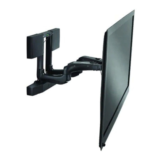
Automated Wall Mount
PXR
Advertisement
Table of Contents

Subscribe to Our Youtube Channel
Related Manuals for CHIEF PXR


Summary of Contents for CHIEF PXR
- Page 1 I N S T A L L A T I O N I N S T R U C T I O N S Automated Wall Mount This device complies with part 15 of the FCC rules. Operation is subject to the following 2 conditions: (1) This device may not cause harmful interference, and (2) this device must accept any interference received, including interference that may cause undesired operation.
-
Page 2: Disclaimer
Exceeding the weight capacity can result in serious personal injury or damage to equipment! The weight capacity of the PXR varies based on the depth of the display (including spacers), but must not exceed 150 lbs READ ALL INSTRUCTIONS BEFORE USING THIS (68.0). -
Page 3: Table Of Contents
PROGRAMMING VIA RS485 ... 24 PXR DIAGRAM ..... . . 9 Setting PXR Address . -
Page 4: Dimensions
Installation Instructions DIMENSIONS 20.45 BACK 519.5 6.36 5.47 17.44 442.9 8.06 9.19 233.4 CENTER OF INTERFACE TO MOUNTING HOLES 45° PAN LEFT 45° PAN RIGHT .739 4.75 18.8 120.6 12.7 16.00 L/R SHIFT 406.4 26.96 684.7 MAX. DISTANCE 4.50 FROM WALL 114.3 29.25 MIN. - Page 5 700mm x 450mm, and use the chart below to determine if display is compatible. NOTE: Not all displays that meet this criteria will be compatible with the PXR.
-
Page 6: Legend
Installation Instructions LEGEND Pencil Mark Tighten Fastener Marcar con lápiz Apretar elemento de fijación Stiftmarkierung Befestigungsteil festziehen Marcar com lápis Apertar fixador Segno a matita Serrare il fissaggio Potloodmerkteken Bevestiging vastdraaien Serrez les fixations Marquage au crayon Loosen Fastener Drill Hole Perforar Aflojar elemento de fijación Bohrloch... -
Page 7: Tools Required For Installation
M5 x 25mm M5 x 16mm M5 x 20mm G (6) H (6) M6 x 16mm M6 x 25mm Q (1) [PXR] K (4) I (6) J (6) M8 x 50mm M8 x 20mm M8 x 30mm NA (8) P (2) -
Page 8: Site Preparation
Locating and Preparing a Mounting Site documentation included with display. The PXR was designed to be installed onto a 16" on center Ensure that an area from the point of PXR wall attachment 2" x 4" wood stud or solid concrete wall; or into the PAC-502 outward and surrounding the PXR is left open and doesn’t... -
Page 9: Pxr Diagram
PXR!! NEVER use the PXR as a vertical lift! ONLY operate the PXR when securely mounted in a vertical position! NEVER operate the PXR while it is lying down or tilting back! IMPORTANT ! : When considering the PXR location,... -
Page 10: Installing To A Wood Stud Wall
INSTALLING TO A WOOD STUD WALL Using a stud finder, locate and mark the two 16" on center 2" x 4" wood studs to which the PXR will be mounted. Determine point for lowest edge of PXR and mark studs. - Page 11 5/16 x 2-1/2" lag screws (RC) and two 5/16" flat washers (RB). (See Figure 7) (RB) x 2 Figure 9 IMPORTANT ! : Do not power the PXR until it is ready to be tested. NOTE: Proceed to Arm Engagement section.
-
Page 12: Installing To A Solid Concrete Wall
OR DAMAGE TO PRODUCT! When installing into concrete, IMPORTANT ! : The anchors must be installed through only install the PXR in a solid concrete wall made of 2500 PSI any wall covering until flush with the concrete wall. (See (17.3 MPa) or stronger concrete. - Page 13 (See Figure 11) and (See Figure 13) 12. Return PXR to mounting bracket. 13. Fasten PXR to wall using two 5/16 x 2-1/2" lag screws (RC) and two 5/16" flat washers (RB). (See Figure 13) (RA) x 2...
-
Page 14: Installing In An In-Wall Box
MOUNT FALLING CAUSING SEVERE PERSONAL INJURY OR DAMAGE TO EQUIPMENT! DO NOT deviate from installation instructions provided. DO NOT substitute hardware. Align mounting holes at top of PXR with two mounting holes in PAC502. (See Figure 16) Figure 18 NOTE: The arms are not engaged in the PXR at this time. - Page 15 12. OPTIONAL: Install PAC502 trim following the instructions included with the PAC502 kit. Figure 21 10. Secure bottom of PXR in PAC502 using two 5/16-18 x 5/8" button head cap screws (CC), two 5/16" split lock washers (EE), and two 1/4" flat washers (DD). (See Figure 22)
-
Page 16: Arm Engagement
Carefully pull arms out from wall. (See Figure 24) Open cable management covers on bottom of PXR arms. Engage PXR arms by lining up pin with opening and using 9" hex head wrench (Y) in opening on bottom of each arm. -
Page 17: Installing Ir Sensor
Installation Instructions Installing IR Sensor Plug IR receiver (AA) into PXR. (See Figure 3) and (See SAVE HOME Figure 26) Route IR receiver to desired location. The IR receiver operates best in open, unobstructed areas. PAN RIGHT NOTE: The final location of the sensor won’t be made until after installation of the display. -
Page 18: Attach Interface Brackets To Display
"learn" the amount of resistance in the installation. Phase A will be automatically run by the PXR. The PXR pans to left limit, back to right limit, repeats, tilts up and returns to HOME position 1. Press and hold [SAVE] for at least 5 seconds, before stopping. -
Page 19: Hanging Display On Pxr
(Display removed for clarity) (U) x 2 (view from front of PXR) Figure 31 IMPORTANT ! : Do NOT operate PXR with display off- center. Measure to verify that display is centered on the PXR. (See Figure 32) Verify this measurement is the same on each side. -
Page 20: Cable Management
(W) and four 1/4-20 x 1/2" hex head cap signal cables in separate PXR arms. screws (U). (See Figure 31) and (See Figure 33) Open cable management covers on top of both PXR arms. (See Figure 34) and (See Figure 35) Figure 35... -
Page 21: Set-Up And Configuration With Display Attached
Open cable management covers on bottom of both PXR If necessary, use cable management flap on PXR base to arms and lay cables within arms. (See Figure 34) and (See route cables from left arm to PXR right side. (See Figure 34) Figure 37) and (See Figure 39) Close cable management covers, being careful to not pinch cables under covers. -
Page 22: Saving A Preset
PXR so that the learning mode can be completed successfully. NOTE: The LEARN MODE is used to calibrate the PXR for use with the specific display which has been attached to it. • If the process is cancelled at any point during Phase A or B it will need to begin again from Phase A. -
Page 23: Final Attachment To Wall Mounting
Replace plastic cover over main circuit board. Emergency Service Extend In the event the PXR needs to be serviced while inside a recessed wall, use the following command sequence to extend the unit out of the recess. This feature is only available in units with software version 40 or greater. -
Page 24: Programming Via Rs485
Determine what address is not used by another Chief automated product. Using the DIP switches on the I/O interface (See Figure 44), set the PXR to one of the unused addresses. (See Figure 45) Figure 45 Access to change If the address of the PXR is changed, the remote control... -
Page 25: Common Commands
Get Product Code Number Get Serial Number Get Status (0x01) Command To use this command and others, the PXR must be connected via an RS485 line with a baud rate of 9600. (See RS-485 Terminal Block Wiring section.) Command Message... -
Page 26: Get System Status (0X2F)
IMPORTANT ! : If the PXR control system sees a fault condition it will stop the operation. A green light will flash on the main control board (visible through the control housing). A red light will flash the same code on top of the unit. - Page 27 Installation Instructions Chief Part Number: 7000-002052 Carrier Frequency: 38KHz Protocol: NEC - Full Repeat System Code(s): 6E (Default) - Multiple codes selected via key-press (See Figure 46) Repeat Code: Key Number Key Name Hex Code HOME SAVE RETRACT SWIVEL LEFT...
-
Page 28: Rs-485 Terminal Block Wiring
Installation Instructions RS-485 Terminal Block Wiring Figure 48 Terminal Block Manufacturer: Molex (See Figure 48) • Terminal Block Manufacturer P/N: 39500-0006 • Terminal Block Pin Outs: 1. Blank 2. TDA (-) 3. TDB (+) 4. Ground 5. Blank 6. Blank •... - Page 29 Installation Instructions...
- Page 30 Installation Instructions...
- Page 31 Installation Instructions...
- Page 32 Europe A Fellenoord 130 5611 ZB EINDHOVEN, The Netherlands P +31 (0)40 2668620 F +31 (0)40 2668615 Chief Manufacturing, a products division Asia Pacific A Office No. 1 on 12/F, Shatin Galleria of Milestone AV Technologies 18-24 Shan Mei Street...
Need help?
Do you have a question about the PXR and is the answer not in the manual?
Questions and answers