Table of Contents
Advertisement
Quick Links
I N S T A L L A T I O N
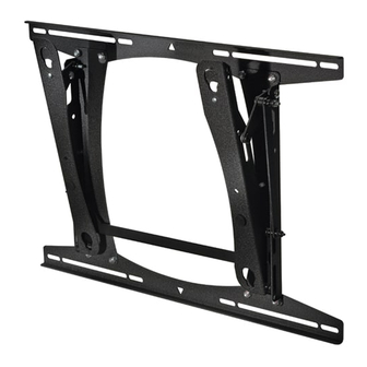
The PLP Series wall mount accommodates large flat
screens weighing up to 200 lbs (90.72kg). The teardrop
holes in the mount allow for quick connect/disconnect of
the screen, thus simplifying installation and maintenance
processes.
The top and bottom mounting brackets are adaptable to
supporting framework with wood studs that are 16" on
center or 24"on center.
The mount has integrated lateral shift, allowing for four
different mounting options. For dual wood studs 16" on
center, the lateral shift is
studs 24" on center, the lateral shift is
The display can be pulled and tilted by hand into any
position in the zero-to-15 degree tilt range and remain
stationary.
The bottom of the mount pulls forward 4" from the wall
and locks into place for installation of cable connections.
The mount also uses Chief's exclusive Q-Latch™
mounting system, which offers quick connect/disconnect
display mounting. The display is secured to the mount
with a latching flag. For additional security, you can lock
the latching flag in place by adding a padlock.
PLP Series Wall Mount
+
4.5 inches. For dual wood
+
0.5 inches.
CHIEF MANUFACTURING INC.
1-800-582-6480 952-894-6280 FAX 952-894-6918
8401 EAGLE CREEK PARKWAY, STE. 700
SAVAGE, MINNESOTA 55378 USA
I N S T R U C T I O N S
PLP Series
8805-000183 Rev F
© 2008 Chief Manufacturing
www.chiefmfg.com
03/08
Advertisement
Table of Contents

Subscribe to Our Youtube Channel
Related Manuals for CHIEF Wall Mount PLP Series


Summary of Contents for CHIEF Wall Mount PLP Series
- Page 1 CHIEF MANUFACTURING INC. 1-800-582-6480 952-894-6280 FAX 952-894-6918 8401 EAGLE CREEK PARKWAY, STE. 700 SAVAGE, MINNESOTA 55378 USA I N S T R U C T I O N S 0.5 inches. PLP Series 8805-000183 Rev F © 2008 Chief Manufacturing www.chiefmfg.com 03/08...
-
Page 2: Before You Begin
The maximum weight to be installed on the PLP Series wall mount is 200 lbs (90.72kg). If you have any questions about this installation, contact Chief Manufacturing at 1-800-582-6480 or 952-582- 6480. -
Page 3: Dimensional Drawing
Installation Instructions DIMENSIONAL DRAWING 26.00 24.00 16.00 16.00 15.51 18.38 13.19 TOP MOUNTING BUTTON ON PSB-XXXX DRAWING GOES HERE 16.00 1.83 1.87 17.00 4.24 FACE TILTS 15 DOWN 7 UP (FOR SERVICE) 5/16" x 1" SLOT 5/16" x 6" SLOT 5/16"... -
Page 4: Table Of Contents
Installation Instructions CONTENTS DIMENSIONAL DRAWING ... 3 TOOLS REQUIRED FOR INSTALLATION... 4 PARTS LIST ... 4 PLP INSTALLATION ... 5 Select Mounting Location... 5 Mount the PLP ... 6 ATTACH PSB TO THE DISPLAY... 7 INSTALL THE DISPLAY ... 7 REMOVE THE DISPLAY... -
Page 5: Plp Installation
Installation Instructions PLP INSTALLATION Perform the following procedures to mount the PLP. Select Mounting Location To select the mounting location, do the following: WARNING: It is the responsibility of the installer to verify that the wall to which the mount is anchored will safely support the combined load of all attached components and equipment. -
Page 6: Mount The Plp
Installation Instructions PLP INSTALLATION (Cont’d) Mount the PLP To mount the PLP, do the following: 1. Holding the PLP against the wall, select the pair of mounting holes that best suits your situation (see Figures 5, 6, and 7). NOTE: The mounting holes are slotted to allow for a small degree of lateral movement. -
Page 7: Attach Psb To The Display
Installation Instructions ATTACH PSB TO THE DISPLAY To attach the PSB to the display, do the following: To help your identify the correct PSB that matches the model number of your display, refer to the cross- reference chart at www.chiefmfg.com. To download the corresponding PSB installation instructions, refer to www.chiefmfg.com. -
Page 8: Tilt Adjustment
Installation Instructions TILT ADJUSTMENT ° ° To tilt the display 0 to 15 down, do the following: ° 1. Manually tilt the display 0 to 15 desired position. 2. If desired, tighten the nut (see Figure 10) to increase the amount of tension needed to hold the mount in the position set in Step 1.
Need help?
Do you have a question about the Wall Mount PLP Series and is the answer not in the manual?
Questions and answers