
Related Manuals for Carrier Transicold 69NT40-561-001


Summary of Contents for Carrier Transicold 69NT40-561-001
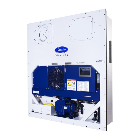
- Page 1 Container Refrigeration OPERATIONS AND SERVICE MANUAL 69NT40-561-001 to 199 Container Refrigeration Units T-340 Rev F...
- Page 3 OPERATIONS AND SERVICE MANUAL 69NT40-561-001 to 199 © 2020 Carrier Corporation Printed in USA August 2020 ●...
- Page 5 TABLE OF CONTENTS PARAGRAPH NUMBER PAGE SAFETY SUMMARY ..............1–1 GENERAL SAFETY NOTICES .
-
Page 6: Table Of Contents
DESCRIPTION ............... . 3–1 GENERAL DESCRIPTION . - Page 7 4.3.23 Defrost Interval ............4–13 4.3.24 Defrost Related Settings .
- Page 8 STARTING AND STOPPING INSTRUCTIONS ........5–7 5.7.1 Starting the Unit .
- Page 9 7.7.2 Adding Refrigerant to System (Full Charge) ........7–7 7.7.3 Adding Refrigerant to System (Partial Charge)
- Page 10 7.24.5 Sensor DTS Reinstallation ..........7–34 7.24.6 Sensor CPDS Reinstallation .
- Page 11 LIST OF ILLUSTRATIONS FIGURE NUMBER Page Figure 3.1 Refrigeration Unit - Front Section ..........3–1 Figure 3.2 Evaporator Section .
- Page 12 Figure 7.18 Sensor and Cable Splice ............7–32 Figure 7.19 Supply Sensor Positioning .
- Page 13 LIST OF TABLES TABLE NUMBER Page Table 3–1 Safety and Protective Devices ........... . 3–9 Table 4–1 Keypad Function .
- Page 15 SECTION 1 SAFETY SUMMARY General Safety Notices The following general safety notices supplement specific warnings and cautions appearing elsewhere in this man- ual. They are recommended precautions that must be understood and applied during operation and maintenance of the equipment covered herein. The general safety notices are presented in the following three sections labeled: First Aid, Operating Precautions and Maintenance Precautions.
- Page 16 WARNING Beware of unannounced starting of the evaporator and condenser fans. The unit may cycle the fans and compressor unexpectedly as control requirements dictate. WARNING Do not attempt to remove power plug(s) before turning OFF start-stop switch (ST), unit circuit breaker(s) and external power source.
- Page 17 WARNING Installation requires wiring to the main unit circuit breaker, CB1.Make sure the power to the unit is off and power plug disconnected before beginning installation. CAUTION Charge water-cooled condenser or receiver according to nameplate specifications to ensure optimal unit performance. CAUTION Do not remove wire harnesses from controller modules unless you are grounded to the unit frame with a static safe wrist strap.
- Page 18 CAUTION The unit will remain in the full cooling mode as long as the EB switch is in the On position and the Mode Switch is in the Full Cool position. If the cargo can be damaged by low temperatures, the operator must monitor container temperature and manually cycle operation as required to maintain temperature within required limits.
- Page 19 INTRODUCTION Introduction The Carrier Transicold model 69NT40-561-001 to 199 series units are of lightweight aluminum frame construction, designed to fit in the front of a container and serve as the container’s front wall. They are one piece, self- contained, all electric units, which include cooling and heating systems to provide precise temperature control.
- Page 20 Option Descriptions Various options may be factory or field equipped to the base unit. These options are described in the following sub- paragraphs. 2.4.1 Battery The refrigeration controller may be fitted with standard replaceable batteries or a rechargeable battery pack. Rechargeable battery packs may be fitted in the standard location or in a secure location.
- Page 21 2.4.13 Water Cooling The refrigeration system may be fitted with a water-cooled condenser. The condenser is constructed using copper- nickel tube for sea water applications. The water-cooled condenser is in series with the air cooled condenser and replaces the standard unit receiver. When operating on the water-cooled condenser, the condenser fan is deacti- vated by a water pressure switch or condenser fan switch.
-
Page 23: Description
SECTION 3 DESCRIPTION General Description 3.1.1 Refrigeration Unit - Front Section The unit is designed so that the majority of the components are accessible from the front (see Figure 3.1). The unit model number, serial number and parts identification number can be found on the unit nameplate to the left of the receiver or water-cooled condenser on the back wall of the condenser section. -
Page 24: Fresh Air Makeup Vent
3.1.2 Fresh Air Makeup Vent The function of the upper or lower fresh air makeup vent is to provide ventilation for commodities that require fresh air circulation. A manually operated venting system is located in the upper left access panel. The optional eAutoFresh vent system moderates the atmospheric level in the container in response to cargo respiration. -
Page 25: Compressor Section
The evaporator fans circulate air through the container by pulling it in the top of the unit, directing it through the evaporator coil, where it is heated or cooled, and discharging it at the bottom. If the unit is equipped with eAutoFresh, system components are mounted in addition to the standard refrigeration unit components. -
Page 26: Air-Cooled Condenser Section
3.1.5 Air-Cooled Condenser Section The air-cooled condenser section (see Figure 3.4) consists of the condenser fan, condenser coil, receiver, liquid line service valve, filter drier, fusible plug, economizer, economizer expansion valve (EXV), economizer solenoid valve (ESV), and sight glass / moisture indicator. The condenser fan pulls air from around the coil and discharges it horizontally through the condenser fan grille. -
Page 27: Water-Cooled Condenser Section
3.1.6 Water-Cooled Condenser Section The water-cooled condenser section (see Figure 3.5) consists of a water-cooled condenser, sight glass, rupture disc, filter drier, water couplings, water pressure switch, economizer, economizer expansion valve, economizer solenoid valve (ESV), and moisture / liquid indicator. The water-cooled condenser replaces the standard unit receiver. -
Page 28: Control Box Section
3.1.7 Control Box Section The control box (see Figure 3.6) includes: the manual operation switches, circuit breaker (CB-1), compressor, fan and heater contactors, control power transformer, fuses, keypad, display module, current sensor module, controller module and the communications interface module. Figure 3.6 Control Box Section 1) Compressor Contactor (CH) 10) Start-Stop Switch (ST) -
Page 29: Refrigeration System Data
Refrigeration System Data Compressor / Motor Assembly Model Number ZMD26KVE-TFD-272 Weight (With Oil) 42.9 kg (95 lb) Approved Oil Uniqema Emkarate RL-32-3MAF Oil Charge 1774 ml (60 ounces) Electronic Expansion Valve Verify at -18°C 4.4 to 6.7°C (8 to 12°F) (EEV) Superheat Evaporator (0F) container box temperature... - Page 30 Condenser Fan Motor 380 VAC, Three Phase, 50 460 VAC, Three Phase, 60 (CM) Full Load Amps 1.3 amps 1.6 amps Horsepower 0.43 hp 0.75 hp Rotations Per Minute 1425 rpm 1725 rpm Voltage and Frequency 360 - 460 VAC +/- 2.5 Hz 400 - 500 VAC +/- 2.5 Hz Bearing Lubrication Factory lubricated, additional grease not required.
-
Page 31: Safety And Protective Devices
Humidity Sensor (HS) Orange wire Power Red wire Output Brown wire Ground Input voltage 5 VDC Output voltage 0 to 3.3 VDC Output voltage readings verses relative humidity (RH) percentage: 0.99 V 1.65 V 2.31 V 2.97 V Controller Setpoint Range -30 to +30°C (-22 to +86°F) Safety and Protective Devices Table... -
Page 32: Refrigeration Circuit
Refrigeration Circuit 3.5.1 Standard Operation Starting at the compressor (see Figure 3.7) the suction gas is compressed to a higher pressure and temperature. The refrigerant gas flows through the discharge line and continues into the air-cooled condenser. When operating with the air-cooled condenser active, air flowing across the coil fins and tubes cools the gas to saturation tempera- ture. -
Page 33: Figure 3.7 Refrigeration Circuit Schematic - Standard Operation
Figure 3.7 Refrigeration Circuit Schematic - Standard Operation SUCTION DISCHARGE LIQUID 1) Compressor 12) Economizer TXV 2) Discharge Service Valve 13) Economizer Solenoid Valve (ESV) 3) Discharge Temperature Sensor (CPDS) 14) Economizer TXV Sensing Bulb 4) Discharge Pressure Transducer (DPT) 15) Electronic Expansion Valve (EEV) 5) Condenser 16) Evaporator... -
Page 34: Figure 3.8 Refrigeration Circuit Schematic - Standard Operation With Water-Cooled Condenser
Figure 3.8 Refrigeration Circuit Schematic - Standard Operation with Water-Cooled Condenser SUCTION DISCHARGE LIQUID 1) Compressor 11) Economizer 2) Discharge Service Valve 12) Economizer TXV 3) Discharge Temperature Sensor (CPDS) 13) Economizer Solenoid Valve (ESV) 4) Discharge Pressure Transducer (DPT) 14) Electronic Expansion Valve (EEV) 5) Condenser 15) Evaporator... -
Page 35: Figure 3.9 Refrigeration Circuit Schematic - Economized Operation
Figure 3.9 Refrigeration Circuit Schematic - Economized Operation LIQUID ECONOMIZER PRESSURE 1) Compressor 5) Economizer TXV 2) Receiver 6) Economizer Solenoid Valve (ESV) 3) Liquid Line Service Valve 7) Economizer TXV Sensing Bulb 4) Economizer 8) Electronic Expansion Valve (EEV) - - - - - 3–13 T-340... -
Page 37: Microprocessor
SECTION 4 MICROPROCESSOR Temperature Control Microprocessor System The temperature control Micro-Link 3 microprocessor system (see Figure 4.1) consists of a keypad, display mod- ule, the control module (controller) and interconnecting wiring. The controller houses the temperature control soft- ware and the DataCORDER software. The temperature control software functions to operate the unit components as required to provide the desired cargo temperature and humidity. -
Page 38: Keypad
4.1.1 Keypad Figure 4.2) is mounted on the right-hand side of the control box. The keypad consists of eleven The keypad (see push button switches that act as the user’s interface with the controller. Descriptions of the switch functions are provided in Table 4–1. -
Page 39: Controller
NOTE The controlling probe in perishable range is the SUPPLY air probe and the controlling probe in frozen range is the RETURN air probe. • SUPPLY - Yellow LED: Energized when the supply air probe is used for control. When this LED is illumi- nated, the temperature displayed in the AIR TEMPERATURE display is the reading at the supply air probe. -
Page 40: Configuration Software (Cnf Variables)
Table 4–4. Change to the factory-installed configuration software is achieved via a configuration card or by communications. Figure 4.4 Control Module EN12830 CONTROLLER With CARRIER Micro-Link3 DataCORDER S/N: 0491162 REV 5147 YYWW: 1035 12-00579-00 T B C1 59980... -
Page 41: Start Up - Compressor Phase Sequence
Operational software responds to various inputs. These inputs come from the temperature and pressure sensors, the temperature set point, the settings of the configuration variables and the function code assignments. The action taken by the operational software changes as the input values change. Overall interaction of the inputs is described as a “mode”... -
Page 42: Perishable Dehumidification
Figure 4.5 Controller Operation - Perishable Mode Pull Down Perishable Mode (Only Applicable to Perishable Mode) −10°C (+14 °F), Controller Set Point ABOVE −10°C (+14 °F), Controller Set Point ABOVE or−5°C (+23 °F) optionally or−5°C (+23 °F) optionally +2.5 °C (+4.5 °F) Cooling, Cooling,... -
Page 43: Perishable Dehumidification - Bulb Mode
Two timers are activated during dehumidification to prevent rapid cycling and consequent contactor wear: 1. Heater debounce timer (three minutes) - The heater debounce timer is started whenever the heater contac- tor status is changed. The heat contactor remains energized (or de-energized) for at least three minutes even if the set point criteria are satisfied. -
Page 44: Perishable Mode Heating - Sequence Of Operation
Figure 4.6 Perishable Mode Cooling ENERGIZED DE-ENERGIZED 24 VOLT POWER IP-CM IP-EM1 IP-EM2 b. When supply air temperature decreases to a predetermined tolerance above set point (Cd30), the green IN RANGE light is illuminated. c. As air temperature continues to fall, unloaded cooling starts (DUV pulses opens) as the supply air tempera- ture approaches set point (see Figure 4.5). -
Page 45: Perishable Mode - Trim Heat
c. The safety heater termination thermostat (HTT) is attached to an evaporator coil circuit and will open the heating circuit if overheating occurs. Figure 4.7 Perishable Mode Heating ENERGIZED DE-ENERGIZED 24 VOLT POWER IP-CM IP-EM1 IP-EM2 NOTE The EEV and DUV are independently operated by the microprocessor. For full diagrams and legend, see Section 4.3.13 Perishable Mode - Trim Heat... -
Page 46: Frozen "Heat" Mode
Figure 4.8 Controller Operation - Frozen Mode Frozen Mode −10°C (+14 °F), Controller Set Point at or BELOW or −5°C (+23 °F) optionally +2.5 °C (+4.5 °F) Cooling, Economized +.20 °C Set Point −.20 °C Air Circulation Falling Rising Temperature Temperature 4.3.17 Frozen “Heat”... -
Page 47: Defrost
b. When the return air temperature decreases to a predetermined tolerance above set point, the green IN- RANGE light is illuminated. c. When the return air temperature decreases to 0.2°C (0.4°F) below set point, contacts TC, TS and TN are opened to de-energize the compressor, economizer solenoid valve and condenser fan motor. -
Page 48: Automatic Defrost
4.3.21 Automatic Defrost In perishable mode, perishable-pull down mode, or frozen mode, automatic defrost starts with an initial defrost set to three hours and then adjusts the interval to the next defrost based on the accumulation of ice on the evaporator coil. -
Page 49: Defrost Interval
Defrost may be initiated any time the defrost temperature sensor reading falls below the controller DTT set point. Defrost will terminate when the defrost temperature sensor reading rises above the DTT set point. The DTT is not a physical component. It is a controller setting that acts as a thermostat, “closing” (allowing defrost) when the defrost temperature sensor reading is below the set point and “opening”... -
Page 50: Protection Modes Of Operation
If controller function code CnF33 is configured to snap freeze, the controller will sequence to this operation. The snap freeze consists of running the compressor without the evaporator fans in operation for a period of 4 minutes at 100% capacity. When the snap freeze is completed, defrost is terminated. If CnF23 is configured to “SAv”... -
Page 51: Condenser Fan Override
4.4.6 Condenser Fan Override When CnF17 (Discharge Temperature Sensor) is set to “In” and CnF48 (Condenser Fan Switch Override) is set to “On”, the condenser fan switch override logic is activated. If condenser cooling water pressure is sufficient to open the water pressure switch (de-energizing the condenser fan) when water flow or pressure conditions are not main- taining discharge temperature, the logic will energize the condenser fan as follows: 1. -
Page 52: Pre-Trip Diagnostics
4.8.1 Description Carrier Transicold “DataCORDER” software is integrated into the controller and serves to eliminate the tempera- ture recorder and paper chart. DataCORDER functions may be accessed by keypad selections and viewed on the display module. The unit is also fitted with interrogation connections (see Figure 4.1) which may be used with the... -
Page 53: Datacorder Software
d. Records DataCORDER and temperature control software generated data and events as follows: • Container ID Change • Software Upgrades • Alarm Activity • Battery Low (battery pack) • Data Retrieval • Defrost Start and End • Dehumidification Start and End •... -
Page 54: Sensor Configuration (Dcf02)
A list of the data points available for recording follows.Changing the configuration to generic and selecting which data points to record may be done using the Carrier Transicold Data Retrieval Program. -
Page 55: Figure 4.11 Standard Configuration Download Report
Table 4–2 DataCORDER Configuration Variables Config Title Default Option dCF01 (Future Use) dCF02 Sensor Configuration 2, 5, 6, 9, 54, 64, 94 dCF03 Logging Interval (Minutes) 15, 30, 60, 120 dCF04 Thermistor Format Short Long dCF05 Thermistor Sampling Type A, b, C dCF06 Controlled Atmosphere / Humidity Sampling Type A, b... -
Page 56: Sampling Type (Dcf05 & Dcf06)
Table 4–3 DataCORDER Standard Configurations Standard Configuration Description 2 sensors (dCF02=2) 2 thermistor inputs (supply & return) 5 sensors (dCF02=5) 2 thermistor inputs (supply & return) 3 USDA thermistor inputs 6 sensors (dCF02=6) 2 thermistor inputs (supply & return) 3 USDA thermistor inputs 1 humidity input 9 sensors (dCF02=9) Not Applicable... -
Page 57: Pre-Trip Data Recording
2. PC communication port(s) unavailable or mis-assigned. 3. Chart Recorder Fuse (FCR) blown. Configuration identification for the models covered herein may be obtained on the Container Products Group Infor- mation Center by authorized Carrier Transicold Service Centers. a. DataReader The Carrier Transicold Data Reader (see Figure 4.12) is a simple to operate hand-held device designed to extract... -
Page 58: Usda Cold Treatment
In response to the demand to replace fumigation with this environmentally sound process, Carrier has integrated Cold Treatment capability into its microprocessor system. These units have the ability to maintain supply air tem- perature within one quarter degree Celsius of set point and record minute changes in product temperature within the DataCORDER memory, thus meeting USDA criteria. -
Page 59: Datacorder Alarms
4. Place the three probes. The probes are placed into the pulp of the product (at the locations defined in the following table) as the product is loaded. Sensor 1 Place in pulp of the product located next to the return air intake. Place in pulp of the product five feet from the end of the load for 40 foot con- Sensor 2 tainers, or three feet from the end of the load for 20 foot containers. -
Page 60: Iso Trip Header
4.8.14 ISO Trip Header DataLINE provides the user with an interface to view/ modify current settings of the ISO trip header through the ISO Trip Header screen. The ISO Trip Header screen is displayed when the user clicks on the “ISO Trip Header” button in the “Trip Func- tions”... -
Page 61: 4.10 Controller Function Codes
Table 4–4 Controller Configuration Variables Config Title Default Option CnF45 Low Humidity Enabled CnF46 Quench/liquid Injection Valve Type nO=0=no nC=1=nc CnF47 Vent Position UP, LOW, CUStOM CnF49 OEM Reset Option 0-off,1-std, 2-spec, 3-cust CnF50 Enhanced Bulb Mode Interface 0-out, 1-in CnF51 Timed Defrost Disable 0-out, 1-in... - Page 62 Table 4–5 Controller Function Codes Code Title Description Cd08 Main Power The value of the main power frequency is displayed in Hertz. The frequency dis- Frequency played will be halved if either fuse F1 or F2 is bad (alarm code AL21). Cd09 Ambient Temperature The ambient sensor reading is displayed.
- Page 63 Table 4–5 Controller Function Codes Code Title Description Configurable Functions - Cd27 through Cd37 are user-selectable functions. The operator can change the value of these functions to meet the operational needs of the container. Cd27 Defrost Interval This is the desired period of time between defrost cycles. Factory default is “AU- (Hours or Automatic) TO”.
- Page 64 Table 4–5 Controller Function Codes Code Title Description Cd31 Stagger Start Offset The stagger start offset time is the amount of time that the unit will delay at start- Time (Seconds) up, thus allowing multiple units to stagger their control initiation when all units are powered up together.
- Page 65 Table 4–5 Controller Function Codes Code Title Description Display Only Functions - Cd38 through Cd40 are display only functions. Cd38 Secondary Supply Cd38 will display the current supply recorder sensor (SRS) reading for units con- Temperature Sensor figured for four probes. If the unit is configured with a DataCORDER, Cd38 will display “-----.”...
- Page 66 Table 4–5 Controller Function Codes Code Title Description Display Only Function - Cd44 is a display only function. Cd44 eAutoFresh Values / Code Cd44 displays the eAutoFresh CO and O values (CO and O ) and CO Sensor Status and O limits (CO LIM and O LIM), respectively.
- Page 67 Table 4–5 Controller Function Codes Code Title Description Cd48 Dehumidification / Initially Cd48 will display current dehumidification-mode; bUlb - bulb cargo Bulb Cargo Mode mode, dEhUM - normal dehumidification, or OFF - off. This display is steady. Parameter Selection Pressing the ENTER key will take the interface down into a hierarchy of param- eter selection menus (mode, setpoint, evaporator speed, DTT setting).
- Page 68 Table 4–5 Controller Function Codes Code Title Description Configurable Functions - Cd50 through Cd53 are user-selectable functions. The operator can change the value of these functions to meet the operational needs of the container. Cd50 CCPC Disabled ”OFF” = disabled. ”On”...
- Page 69 Table 4–5 Controller Function Codes Code Title Description Cd53 Automatic Set point ASC-mode: Change Mode Cd53 increments of (1 day)_(1hr), Display: default “0_0 “ Parameter Selection “done” mm-dd this will be display is ASC has completed “ASC” value “On” “OFF” Display /Select: default “OFF“ “nSC”...
- Page 70 Table 4–5 Controller Function Codes Code Title Description Cd58 Water Pressure Cd58 will display “CLOSE” if the WPS or CFS switch contacts are closed or if Switch / Condenser these options are not installed. “OPEn” is displayed when the WPS or CFS Fan Switch State or switch contacts are open.
- Page 71 Table 4–5 Controller Function Codes Code Title Description Cd70 Temp Setpoint Lock Cd70 locks out setpoint selection, requiring the user to manually turn the lock off, prior to making a setpoint change. If the setpoint lock is “ON”, and the user at- tempts to enter a new setpoint, a message “SPLK”...
-
Page 72: Figure 4.13 Alarm Troubleshooting Sequence
Figure 4.13 Alarm Troubleshooting Sequence Start Refer to Connect Power Check Power Unit does Supply Section 5.2 self test? Refer to Connect Power Check Power Evaporator Section 5.2 Supply fans start? Refer to Controller Software Correct Install Latest software Software Section 4.2 version? Revision... -
Page 73: 4.11 Controller Alarm Indications
4.11 CONTROLLER ALARM INDICATIONS Table 4–6 Controller Alarm Indications Alarm Code Cause Components Troubleshooting Corrective Actions AL03 Superheat has re- Electronic Expan- Check the operation of Replace EEV if defec- Loss of Super- mained below 1.66°C sion Valve (EEV) the EEV using Cd41. tive. - Page 74 Table 4–6 Controller Alarm Indications Alarm Code Cause Components Troubleshooting Corrective Actions AL14 Controller is unable to Power cycle the unit. Resetting the unit may Phase determine the correct correct problem, monitor Sequence De- phase relationship. the unit. tect Fault Wiring Check unit wiring.
- Page 75 Table 4–6 Controller Alarm Indications Alarm Code Cause Components Troubleshooting Corrective Actions AL17 Compressor has at- Controller will attempt Resume normal Compressor tempted to start in both restart every 20 minutes operation. Pressure Delta directions and fails to and deactivate the alarm Fault generate sufficient if successful.
- Page 76 Table 4–6 Controller Alarm Indications Alarm Code Cause Components Troubleshooting Corrective Actions AL19 Discharge temperature Restrictions in the Ensure the Discharge Open the Discharge Ser- Discharge exceeds 135°C refrigeration sys- Service Valve is fully vice Valve as needed. Temperature (275°F) for 10 minutes tem.
- Page 77 Table 4–6 Controller Alarm Indications Alarm Code Cause Components Troubleshooting Corrective Actions AL25 Condenser fan motor Insufficient Air Shut down unit and Remove obstructions. Condenser IP internal protector (IP) is Flow check condenser fan for open. obstructions. Condenser Fan Shut down unit, discon- Replace defective con- Motor nect power, &...
- Page 78 Table 4–6 Controller Alarm Indications Alarm Code Cause Components Troubleshooting Corrective Actions AL52 Alarm list queue is full Active Alarms Repair any alarms in the Clear alarms, refer to EEPROM Alarm queue that are active. In- CONTROLLER List Full dicated by “AA”. ALARMS Section 4.6.
- Page 79 Table 4–6 Controller Alarm Indications Alarm Code Cause Components Troubleshooting Corrective Actions AL61 Improper current draw Heater(s) While in heat or defrost Replace heater(s) if de- Heater Current during heat or defrost mode, check for proper fective, refer to Section Draw Fault mode.
- Page 80 Table 4–6 Controller Alarm Indications Alarm Code Cause Components Troubleshooting Corrective Actions AL70 Secondary Supply Secondary Sup- Perform Pre-trip P5: If P5 passes, no further Secondary Sup- Sensor (SRS) is out of ply Sensor (SRS) action is required. ply Sensor range.
- Page 81 Table 4–6 Controller Alarm Indications Alarm Code Cause Components Troubleshooting Corrective Actions ERR # Internal The controller performs self-check routines. If an internal failure occurs, Microprocessor an “ERR” alarm will appear on the display. This is an indication the con- Failure troller needs to be replaced.
-
Page 82: 4.12 Controller Pre-Trip Test Codes
4.12 Controller Pre-Trip Test Codes NOTE “Auto” or “Auto1” menu includes the: P0, P1, P2, P3, P4, P5, P6 and rSLts. “Auto2” menu includes P0, P1, P2, P3, P4, P5, P6, P7, P8, P9, P10 and rSLts. “Auto3” menu includes P0, P1, P2, P3, P4, P5, P6, P7 and P8. Table 4–7 Controller Pre-trip Test Codes Code Description... - Page 83 Table 4–7 Controller Pre-trip Test Codes P3-0 Low Speed Evaporator High speed evaporator fans will be turned on for 20 seconds, the fans will Fan Motors On be turned off for 4 seconds, current draw is measured, and then the low speed evaporator fans are turned on.
- Page 84 Table 4–7 Controller Pre-trip Test Codes P5-2 Return Probe Test For units equipped with secondary return probe only. The temperature difference between return temperature sensor (RTS) and return temperature sensor (RRS) probe is compared. Test passes if temperature comparison falls within the specified range. NOTES 1.
- Page 85 Table 4–7 Controller Pre-trip Test Codes P6 Tests - Refrigerant Probes, Compressor and Refrigerant Valves: Pass/Fail testing is performed for the compressor, EEV, DUV, LIV (if equipped), ESV, and the refrigerant pressure and temperature sensors. P6-0 Discharge Thermistor Test If Alarm 64 is active the test fails. Otherwise, the test passes. P6-1 Suction Thermistor Test If the Suction Temperature Sensor (CPSS) both is configured ON and is...
- Page 86 Table 4–7 Controller Pre-trip Test Codes P7 Tests - High Pressure Tests: Unit is run at full capacity without condenser fan running to make sure that the HPS opens and closes properly. NOTE P7-0 & P8 are included with “Auto 2 & Auto 3” only. P9-0 through P10 are included with “Auto2” only. P7-0 High Pressure Switch Test is skipped if sensed ambient temperature is less than 7.2°C (45°F),...
- Page 87 Table 4–7 Controller Pre-trip Test Codes P8-1 Perishable Mode Pull Control temperature must be at least 15.6°C (60°F). Down Test / eAutofresh The set point is changed to 0°C (32°F), and a 180-minute timer is started. Sensor Calibration The left display will read “P8-1,” the right display will show the supply air temperature.
- Page 88 Table 4–7 Controller Pre-trip Test Codes P10 Tests - Frozen Mode Tests: P10-0 Frozen Mode Heat Test If the container temperature is below 7.2°C, the setpoint is changed to 7.2°C, and a 180 Minute timer is started. The control will then be placed in the equivalent of normal heating.
-
Page 89: Table 4-8 Datacorder Function Code Assignments
Table 4–8 DataCORDER Function Code Assignments NOTE Inapplicable Functions Display “-----” To Access: Press the ALT. MODE key Code Title Description Recorder Supply Temperature Current reading of the supply recorder sensor. Recorder Return Temperature Current reading of the return recorder sensor. dC3-5 USDA 1, 2, 3 Temperatures Current readings of the three USDA probes. -
Page 90: Table 4-9 Datacorder Pre-Trip Result Records
Table 4–9 DataCORDER Pre-trip Result Records Test Title Data Heater On Pass / Fail / Skip Result, Change in currents for Phase A, B and C Heater Off Pass / Fail / Skip Result, Change in currents for Phase A, B and C Condenser Fan On Pass / Fail / Skip Result, Water pressure switch (WPS) - Open / Closed;... -
Page 91: Table 4-10 Datacorder Alarm Indications
Table 4–10 DataCORDER Alarm Indications To Access: Press ALT. MODE key then ALARM LIST key Code Title Description dAL70 Recorder Supply Temperature The supply recorder sensor reading is outside of the range of -50°C Out of Range to 70°C (-58°F to +158°F), or the probe check logic has determined there is a fault with this sensor. -
Page 93: Operation
SECTION 5 OPERATION Inspection (Before Loading) WARNING Beware of unannounced starting of the evaporator and condenser fans. The unit may cycle the fans and compress or unexpectedly as control requirements dictate. 1. Check inside for the following: • Check channels or “T” bar floor for cleanliness. Channels must be free of debris for proper air circulation. •... -
Page 94: Adjust Fresh Air Makeup Vent
2. Make sure the circuit breakers CB-1 (in the control box) and CB- 2 (on the transformer) are in position “0” (OFF). 3. Plug in and lock the 460VACpower plug at the receptacle on the transformer. 4. Plug the 230 VAC (black) cable into a de-energized 190/230 VAC, 3-phase power source and energize the power source. -
Page 95: Lower Fresh Air Makeup Vent
Figure 5.2 Upper Fresh Air Make Up Flow Chart FLOW (CMH) 50HZ TBAR 1 1/2” TBAR 2 5/8” TBAR 3” PERCENT OPEN FLOW (CMH) 60HZ TBAR 1 1/2” TBAR 2 5/8” TBAR 3” PERCENT OPEN 5.3.2 Lower Fresh Air Makeup Vent a. -
Page 96: Vent Position Sensor
On some models the air slide is supplied with two adjustable air control discs. The fresh air makeup can be adjusted for 15, 35, 50 or 75 cubic meters per hour (CMH). The air flow has been established at 60 Hz power and 2-1/2 inch T bar and with 15 mm (0.6 inch) H O external static above free blow. -
Page 97: Eautofresh Pre-Trip Inspection
5.4.1 eAutoFresh Pre-Trip Inspection Pre-trip testing of the eAutoFresh system is performed during Pre-Trip test P0. Operation of the system may be observed during this test. Upon initiation of Pre-Trip P0, the current state will be saved and the vent will fully close. This will be followed by two sequences of opening to 100% and returning to the closed position. -
Page 98: Connect Water-Cooled Condenser
d. DELAY In DELAY mode, the operation of the eAutoFresh system will be delayed for a set amount of time. This allows time for the cargo to reach set point. In DELAY mode, the eAutoFresh vent will open to the stored (FLO) value when the return air temperature sensor (RTS) is at or below set point plus the return offset value (rtn) or the delay time (tIM), whichever comes first. -
Page 99: Water-Cooled Condenser With Condenser Fan Switch
2. Maintain a flow rate of 11 to 26 liters per minute (3 to 7 gallons per minute). The water pressure switch will open to de-energize the condenser fan relay. The condenser fan motor will stop and will remain stopped until the water pressure switch closes. -
Page 100: Stopping The Unit
5.7.2 Stopping the Unit 1. To stop the unit, place the START-STOP switch in position “0” (OFF). Start-Up Inspection 5.8.1 Physical Inspection Check rotation of condenser and evaporator fans. 5.8.2 Check Controller Function Codes Check, and if required, reset controller Function Codes (Cd27 through Cd39) in accordance with desired operating Table 4–5, Controller Function Codes. -
Page 101: Prior To Starting A Pre-Trip
When only the short sequence is configured, it will appear as “AUtO” in the display. Otherwise “AUtO1” will indicate the short sequence and “AUtO2” will indicate the long sequence. The test short sequence will run tests P0 through P6. The long test sequence will run tests P0 through P10. A detailed description of the Pre-trip test codes is listed in Table 4–7. -
Page 102: Displaying Pre-Trip Test Results
• Individually selected tests, other than the LED / Display test, will perform the operations necessary to ver- ify the operation of the component. At the conclusion, “PASS” or “FAIL” will be displayed. This message will remain displayed for up to three minutes, during which time a user may select another test. If the three minute time period expires, the unit will terminate pre-trip and return to control mode operation. -
Page 103: 5.11 Emergency Bypass Operation
5.11 Emergency Bypass Operation Emergency Bypass operation is used to override the controller, in the case of a controller malfunction, to keep the unit cooling. When Emergency Bypass is installed and turned on, the unit will remain in a continuous state of full cool until the Emergency Bypass switch is turned off. -
Page 104: Automatic Cold Treatment (Option)
Automated Cold Treatment (ACT) in the Carrier Transicold unit is a method to simplify the task of completing cold treatment by automating the process of changing the setpoints. ACT is set up through function code Cd51. Refer to Function Code table in this manual for Cd51 menu processing and displays. - Page 105 NOTE "trEAt" is the maximum value that the USDA probes need to remain below, to pass the Cold Treatment pro- tocol. For instance, if the treat value is set at 35.0°F (1.7°C) then the USDA probe temperatures must remain below 35.0°F (1.7°C) to pass. COOL HEAT DEFROST...
-
Page 106: Automatic Setpoint Change (Asc)
12. When the cold treatment process is complete, the "SPnEW" setpoint will be displayed in the left hand dis- play and cargo temperature in the right hand display, alternating with "COLd" "Done". "COLd" "Done" will continue to alternate with the setpoint and cargo temperature until ACT is turned off. COOL HEAT DEFROST... -
Page 107: Troubleshooting
SECTION 6 TROUBLESHOOTING Condition Possible Cause Remedy / Reference Unit Will Not Start Or Starts Then Stops External power source OFF Turn on Start-Stop switch OFF or defective Check No power to unit Circuit breaker tripped or OFF Check Autotransformer not connected Section 5.2.2 Circuit breaker OFF or defective Check... -
Page 108: Unit Runs But Has Insufficient Cooling
Condition Possible Cause Remedy / Reference Unit Runs But Has Insufficient Cooling Section 6.7 Abnormal pressures Section 6.16 Abnormal temperatures Abnormal currents Section 6.17 Controller malfunction Section 6.9 Evaporator fan or motor defective Section 7.15 Refrigeration system Compressor service valves or liquid line shutoff valve Open valves completely partially closed Frost on coil... -
Page 109: Abnormal Pressures
Condition Possible Cause Remedy / Reference Manual defrost switch defective Replace Will not initiate defrost Keypad is defective Replace manually Defrost temperature sensor open Replace Initiates but relay (DR) Low line voltage Section 3.3 drops out Heater contactor or coil defective Replace Initiates but does not defrost Heater(s) burned out... -
Page 110: Microprocessor Malfunction
Condition Possible Cause Remedy / Reference Microprocessor Malfunction Incorrect software and / or controller configuration Check Section 7.24 Defective sensor Will not control Defective wiring Check Low refrigerant charge Section 7.3 6.10 No Evaporator Air Flow Or Restricted Air Flow Frost on coil Section 6.6 Evaporator coil blocked... -
Page 111: 6.13 Autotransformer Malfunction
Condition Possible Cause Remedy / Reference Foreign material in valve Section 7.17 Failed suction pressure transducer (SPT) or evapora- Replace tor pressure transducer (EPT) High suction pressure with low superheat Electronic expansion valve (EEV) control malfunction Replace Improperly seated powerhead Ensure powerhead is locked and in place Failed suction pressure transducer (SPT) or evapora-... -
Page 112: 6.16 Abnormal Temperatures
Condition Possible Cause Remedy / Reference 6.16 Abnormal Temperatures Section 7.10 Condenser coil dirty Section 7.11 Condenser fan rotating backwards Condenser fan inoperative Section 7.11 Refrigerant overcharge or non-condensibles Section 7.3 Discharge service valve partially closed Open Electronic expansion valve (EEV) control malfunction Replace Failed suction pressure transducer (SPT) or evapora- Replace High discharge temperature... -
Page 113: Service
SECTION 7 SERVICE NOTE Use a refrigerant recovery system whenever removing refrigerant.When working with refrigerants you must comply with all local government environmental laws. In the U.S.A., refer to EPA section 608. WARNING EXPLOSION HAZARD: Failure to follow this WARNING can result in death, serious personal injury and / or property damage. -
Page 114: Service Connections
A R-134a manifold gauge/hose set with self-sealing hoses (see Figure 7.2) is required for service of the models covered within this manual. The manifold gauge/hose set is available from Carrier Transicold. (Carrier Transicold part number 07-00294-00, which includes items 1 through 6, Figure 7.2.) -
Page 115: Connecting The Manifold Gauge Set
With the valve stem midway between frontseat and backseat, both of the service valve connections are open to the access valve path. For example, the valve stem is first fully backseated when connecting a manifold gauge to measure pressure. Then, the valve is opened 1/4 to 1/2 turn to measure the pressure. Figure 7.3 Service Valve 1) Line Connection 5) Compressor Or Filter Drier Inlet Connection... -
Page 116: Pump Down The Unit
Pump Down the Unit To service the filter drier, economizer, expansion valves, economizer solenoid valve, digital unloader valve or evap- orator coil, pump the refrigerant into the high side as follows: CAUTION The scroll compressor achieves low suction pressure very quickly. Do not use the compressor to evacuate the system below 0 psig. -
Page 117: Evacuation And Dehydration
2. Essential tools to properly evacuate and dehydrate any system include a vacuum pump (8m3/hr = 5 cfm vol- ume displacement) and an electronic vacuum gauge. The pump is available from Carrier Transicold, P/N 07-00176-11. The micron gauge is P/N 07- 00414- 00. -
Page 118: Evacuate And Dehydrate - Partial System
2. The recommended method to evacuate and dehydrate the system is to connect evacuation hoses at the Figure 7.4). Be sure the service hoses are suited for compressor suction and liquid line service valve (see evacuation purposes. 3. Test the evacuation setup for leaks by backseating the unit service valves and drawing a deep vacuum with the vacuum pump and gauge valves open. - Page 119 7.7.2 Adding Refrigerant to System (Full Charge) Section 7.6.1). 1. Evacuate unit and leave in deep vacuum (see 2. Place cylinder of R-134a on scale and connect charging line from cylinder to liquid line valve. Purge charging line at liquid line valve and then note weight of cylinder and refrigerant. 3.
-
Page 120: Figure 7.5 Compressor Kit
2. Frontseat the manual liquid line valve and allow the unit to pull-down to 0.1 kg/cm (1 psig). 3. Turn the unit start-stop switch (ST) and unit circuit breaker (CB-1) OFF, and disconnect power to the unit. 4. Frontseat the discharge and suction service valves. 5. - Page 121 13. Cut and discard the wire ties used to hold the base plate to the compressor. 14. Place the new SST washers on each side of the resilient mounts, and the new Mylar washer on the bottom of it (see Figure 7.5).
-
Page 122: Figure 7.6 High Pressure Switch Testing
Figure 7.6 High Pressure Switch Testing 1) Cylinder Valve and Gauge 4) Pressure Gauge (0 to 36 kg/cm = 0 to 400 psig) 2) Pressure Regulator 5) Bleed-Off Valve 3) Nitrogen Cylinder 6) 1/4 inch Connection - - - - - 4. - Page 123 7.11 Condenser Fan and Motor Assembly WARNING Do not open the condenser fan grille before turning power OFF and disconnecting the power plug. The condenser fan rotates counter-clockwise (viewed from front of unit), pulls air through the condenser coil, and discharges horizontally through the front of the unit.
- Page 124 NOTE When Oakite Compound No. 32 is used for the first time, the local Oakite Technical Service representa- tive should be called in for suggestions in planning the procedure. The representative will advise the reader on how to do the work with a minimum dismantling of equipment: how to estimate the time and amount of compound required;...
-
Page 125: Figure 7.7 Water-Cooled Condenser Cleaning, Forced Circulation
Figure 7.7 Water-Cooled Condenser Cleaning, Forced Circulation 1) Pump support 7) Vent 2) Tank 8) Close vent pipe valve when pump is running 3) Suction 9) Condenser 4) Pump 10) Remove water regulating valve 5) Priming Connection (Centrifugal pump 50 gpm at 35’ head) 11) Return 6) Globe valves 12) Fine mesh screen... -
Page 126: Figure 7.8 Water-Cooled Condenser Cleaning - Gravity Circulation
Figure 7.8 Water-Cooled Condenser Cleaning - Gravity Circulation 3’ to 4’ 1) Fill condenser with cleaning 2) Approximately 5’ solution. Do not add solution more 3) Condenser rapidly than vent can exhaust 4) Vent pipe gases caused by chemical action. 5) 1”... - Page 127 7.13.2 Replacing the Filter Drier 1. Pump down the unit (see Section 7.4). Evacuate if unit is not equipped with service valves. Then replace fil- ter drier. 2. Evacuate the low side (see Section 7.6). 3. After unit is in operation, inspect for moisture in system and check charge. 7.14 Evaporator Coil &...
-
Page 128: Figure 7.9 5+1 Heater Arrangement - Omega Heater
Figure 7.9): b. To remove Omega heater (see 1. Remove the two tube clamps located near the top of the heater element. 2. Locate the holding clips positioned at the bottom of the heater element and rotate slightly toward the center of the container unit. -
Page 129: Figure 7.10 Evaporator Fan Assembly
Analyses by Carrier Transicold environmental specialists have identified the white powder as consisting predominantly of aluminum oxide. Aluminum oxide is a coarse crystalline deposit most likely the result of surface corrosion on the 7–17... - Page 130 Pow’r® HD) for the unit. This will assist in helping to remove the corrosive fumigation chemicals and dislodging of the corrosive elements. This cleaner is available from the Carrier Transicold Performance Parts Group (PPG) and can be ordered through any of the PPG locations; Part Number NU4371-88.
-
Page 131: Figure 7.11 Electronic Expansion Valve
7.17.2 Installing an EEV 1. Reverse steps 1 through 4 above to install a new valve. Install valve and screen with cone of screen pointing into liquid line at inlet to the valve. 2. During installation, make sure the EEV coil is snapped down fully, and the coil retention tab is properly seated in Figure 7.11). -
Page 132: Figure 7.13 Economizer Expansion Valve
7.18.2 Removing the Solenoid Valve 1. Pump down the compressor (see Section 7.4) and frontseat both suction and discharge valves. 2. Remove the valve. The preferred method of removing the solenoid valve is to cut the connection between the brazed section and the valve, using a small tube cutter. Remove the valve. Alternately, heat inlet and outlet connections to valve body and remove valve. -
Page 133: Figure 7.14 View Of Digital Unloader Valve (Duv) Assembly
6. Remove the valve. The preferred method of removing the valve is to cut the connection between the brazed section and the valve, using a small tube cutter. Remove the valve. Alternately, use a wet rag to keep valve cool. Heat inlet and outlet connections to valve body and remove valve. 7. - Page 134 7. Examine compressor and service valves. Ensure that the O-ring is not stuck in the gland of the valve. 8. Discard the O-ring on the O-ring face seal connection. 7.20.2 Installing the DUV: 1. Lubricate the gland shoulder area and O-ring with refrigerant oil. 2.
-
Page 135: Figure 7.15 Autotransformer
Table 7–1 Valve Override Control Displays Left Display Controller Communications Codes Setting Codes (Right Display) (Right Display) Cd 41/SELCt 0 00 (0 minutes/0 Seconds) (Override Timer) In 30 second increments to 5 00 (5 minutes/ 0 seconds) PCnt AUtO (% Setting - DUV Capacity Modulation) (Normal Machinery Control) AUtO (% Setting - Electronic Expansion Valve) -
Page 136: Table 7-2 Test Point Descriptions
1. Obtain a grounding wrist strap (Carrier Transicold P/N 07-00304-00) and a static dissipation mat (Carrier Transicold P/N 07-00277-00). The wrist strap, when properly grounded, will dissipate any potential static buildup on the body. -
Page 137: Figure 7.16 Controller Section Of The Control Box
Figure 7.16 Controller Section of the Control Box 1) Controller Software Programming Port 3) Controller 2) Mounting Screw 4) Test Points - - - - - 7.23.3 Controller Programming Procedure CAUTION The unit must be OFF whenever a programming card is inserted or removed from the controller programming port. - Page 138 10. Turn power on and wait about 15 seconds for the new software to load into the controller memory. The sta- tus LED will flash quickly and the display will remain blank as the controller loads the new software. When complete, the controller will reset and power up normally.
- Page 139 10. Turn power on and wait about 15 seconds for the new software to load into the controller memory. The sta- tus LED will flash quickly and the display will remain blank as the controller loads the new software. When complete, the controller will reset and power up normally. 11.
- Page 140 d. Procedure for Setting the Container ID: NOTE The characters will be preset to the container ID already on the controller. If none exist, the default will be AAAA0000000. 1. Press the Up or Down Arrow key until display reads Set ID. 2.
- Page 141 3. Disconnect the battery wires from the “KA” plug positions 14, 13, 11. 4. Using Driver Bit, Carrier Transicold part number 07-00418-00, remove the 4 screws securing the display module to the control box. Disconnect the ribbon cable and set the display module aside.
-
Page 142: Table 7-3 Sensor Resistance - Ambs, Dts, Ets, Rrs, Rts, Srs, Sts
Table 7–3 Sensor Resistance - AMBS, DTS, ETS, RRS, RTS, SRS, STS °C °F OHMS °C °F OHMS 336,500 42.8 24,173 -38.2 314,773 44.6 23,017 -36.4 294,600 46.4 21,922 -34.6 275,836 48.2 20,886 -32.8 258,336 19,900 242,850 51.8 18,975 -29.2 228,382 53.6 18,093... -
Page 143: Table 7-4 Sensor Resistance - Primeline Cpds
Table 7–4 Sensor Resistance - PrimeLINE CPDS °C °F OHMS °C °F OHMS 2,889,600 64.4 117,656 -36.4 2,532,872 68.0 107,439 -32.8 2,225,078 71.6 98,194 -29.2 1,957,446 75.2 89,916 -25.6 1,724,386 86,113 -22.0 1,522,200 78.8 82,310 -18.4 1,345,074 82.4 75,473 -14.8 1,190,945 83.0 69,281... -
Page 144: Figure 7.17 Sensor Types
Figure 7.17 Sensor Types Mounting Stud Type Bulb Type 1) 40 mm (1 1/2 in), 2 or 3 wires as 2) 6.3 mm (1/4 in). required - - - - - 5. Strip back insulation on all wiring 6.3 mm (1/4 inch). 6. -
Page 145: Figure 7.19 Supply Sensor Positioning
Figure 7.18) and re-check sensor resistance. 13. Position sensor in unit (see 14. Reinstall sensor (see Section 7.24.3). NOTE Section 5.9). The P5 Pre-Trip test must be run to deactivate probe alarms (see 7.24.3 Sensors STS and SRS Reinstallation To properly position a supply sensor, the sensor must be fully inserted into the probe holder mounting clamp. See Figure 7.19. -
Page 146: Sensor Dts Reinstallation
7.24.4 Sensors RRS and RTS Reinstallation Figure 7.21). For proper placement of the return sensor, be sure to position the Reinstall the return sensor (see enlarged positioning section of the sensor against the side of the mounting clamp. Figure 7.20 Return Sensor Positioning 1.50 in. -
Page 147: Vent Position Sensor (Vps)
Figure 7.22 Compressor Discharge Temperature Sensor 1) Sensor 3) Sensor Well 2) Silicon Bead - - - - - 3. Using the syringe supplied with the replacement sensor, squeeze all of the dielectric compound into the sen- sor well. 4. Place a bead of the silicone sealer supplied with the replacement sensor around the sensor sealing ring. Insert sensor into the well with the leads parallel to the suction fitting. -
Page 148: Humidity Sensor (Hs)
2. Rotate the gear clockwise until it stops. 3. Rotate the gear 1/4 turn counterclockwise. 4. Carefully reposition the slide onto the air makeup panel, given that the gear is engaged with the rail and has not moved. 5. Position slide panel to the fully closed position. 6. - Page 149 NOTE Make sure that the sensor is not at all in contact with the salt water. Cap hole (3 cm) Cap opening (6 cm) Humidity Sensor Salt water solution 10. Allow the saturated salt mixture to settle for approximately ten minutes. 11.
-
Page 150: 7.27 Eautofresh Service
2. To check with a SMA-12 portable stepper drive tester. The SMA-12 portable stepper drive tester (Carrier Transicold P/N 07-00375-00) is a battery operated stepper drive which will open and close the auto slide, which allows a more thorough check of the motor. -
Page 151: Checking The Controller
Checking the outputs on A, B and E will verify that the controller is supplying power to the drive module. To be thor- ough, and if it is desired, the signals on pins C and D can be checked as follows: 1. Install a jumper assembly (Carrier part number 07-00408-00) to connect the drive module and controller Figure 7.24). -
Page 152: Servicing The Eautofresh Drive System
7.27.4 Servicing the eAutoFresh Drive System To replace the Drive Motor Assembly: Figure 7.25) to the front of the unit. Reach in, cut tie 1. Remove the bolts that secure the eAutoFresh Panel (3, wrap, (2) and disconnect the motor connector (1). Bring panel to work area. 2. -
Page 153: 7.28 Electronic Partlow Temperature Recorder
Figure 7.25 Motor Cup Replacement 1) Connector 7) Grille 2) Tie Wrap 8) Grill Screws 3) eAutoFresh Panel 9) Rail Screws 4) Cup, Motor 10) Plate, Slide 5) Rail, Top 11) Rail, Bottom 6) Plate, Gasket 12) Motor Cup Screws - - - - - 7.28 Electronic Partlow Temperature Recorder The microprocessor-based temperature recorder is designed to interface with the DataCORDER to log tempera-... -
Page 154: Replacing The Recorder
If using the Electronic Partlow Recorder CTD part number 12-00464-xx, Where xx= an even number (example: 12-00464-08) The recorder will STOP when the power is OFF, and the pen tip will remain at the last recorded temperature on the chart. When power is applied, and the power off period is less than thirty days, the recorder will retrieve the logged data from the DataCORDER for the power off period and record it onto the chart. -
Page 155: Recalibrating The Temp Recorder To Zero
7.28.2 Recalibrating the Temp Recorder to Zero For Electronic Partlow Recorder CTD part number 12-00464-xx, Where xx= an odd number (example: 12-00464-03) NOTE Use chart CTD: part number 09-00128-00 (F), part number 09-00128-01 (C). 1. Press the “Calibration” button (see item 7, Figure 7.26) on the bottom of the recorder. -
Page 156: Installing The Module
Units that have been factory provisioned for installation of a Communication Interface Module (CIM) have the required wiring installed. If the unit is not factory provisioned, a provision wiring kit (Carrier Transicold part number 76-00685-00) must be installed. Installation instructions are packaged with the kit. - Page 157 Table 7–5 R-134a Refrigerant Pressure Temperature Chart Note: Underline figures are inches of mercury vacuum °F °C PSIG °C °F -15.6 -0.4 0.45 -14.4 0.51 -13.3 10.8 0.57 -12.2 11.9 0.64 -11.1 13.1 0.71 -10.0 14.4 0.78 -8.9 15.7 10.4 0.85 -7.8 17.0...
- Page 158 Table 7–5 R-134a Refrigerant Pressure Temperature Chart Note: Underline figures are inches of mercury vacuum °F °C PSIG °C °F 31.1 100.6 75.2 5.46 32.2 104.3 77.0 5.65 33.3 108.1 78.8 5.85 34.4 112.0 80.6 6.06 35.6 115.9 82.4 6.27 36.7 120.0 84.2...
- Page 159 7–47 T-340...
-
Page 160: Table 7-6 Recommended Bolt Torque Values (Dry, Non-Lubricated For 18-8 Stainless Steel)
Table 7–6 Recommended Bolt Torque Values (Dry, Non-Lubricated for 18-8 Stainless Steel) Bolt Diameter Threads In-Lbs. Ft-Lbs. Free Spinning 5/16 14.9 27.1 7/16 58.3 9/16 77.3 1104 124.7 1488 168.1 Non Free Spinning (Locknuts etc.) 82.5 5/16 145.2 12.1 16.4 22.0 29.8 7/16... -
Page 161: Electrical Wiring Schematics
SECTION 8 ELECTRICAL WIRING SCHEMATICS Introduction This section contains the Electrical Schematics and Wiring Diagrams. The diagrams are presented as follows: Figure 8.1 provides the legend for use with Figure 8.2. Figure 8.2 provides the basic schematic diagram for standard refrigeration units. Figure 8.3 provides the legend for use with Figure... -
Page 162: Figure 8.1 Legend For Standard Unit Configuration
Figure 8.1 Legend for Standard Unit Configuration LEGEND SYMBOL DESCRIPTION SYMBOL DESCRIPTION AMBS AMBIENT SENSOR (C 21) HEATER CONTACTOR (P 4, M 13) CONTROLLER (J 19) HUMIDITY SENSOR (F 21) CIRCUIT BREAKER 460 VOLT (F 1) HEAT TERMINATION THERMOSTAT (G 13) CONDENSER FAN CONTACTOR (M 11, P 6) INTERROGATOR CONNECTOR FRONT (T 21) COMPRESSOR CONTACTOR (M 7, P 1) -
Page 163: Figure 8.2 Schematic Diagram For Standard Unit Configuration
Figure 8.2 Schematic Diagram for Standard Unit Configuration Based on Drawing 62 −11271 Rev A 8–3 T-340... -
Page 164: Figure 8.3 Legend For Configuration With Available Options
Figure 8.3 Legend for Configuration With Available Options (Except Vent Positioning System, eAutoFresh, Emergency Bypass Options) LEGEND SYMBOL DESCRIPTION SYMBOL DESCRIPTION AMBS AMBIENT SENSOR (C 21) HIGH PRESSURE SWITCH (G 7) CONTROLLER (J 19) HEATER CONTACTOR (P 4, P 5, M 13) CIRCUIT BREAKER 460 VOLT (H 1) HUMIDITY SENSOR (OPTIONAL) (F 21) -
Page 165: Figure 8.4 Schematic Diagram For Configuration With Available Options
Figure 8.4 Schematic Diagram for Configuration With Available Options (Except Vent Positioning System, eAutoFresh, Emergency Bypass Options) see Figure 7 −7 for VPS Based on Drawings 62 −66721 and 62 −11271 Rev A 8–5 T-340... -
Page 166: Figure 8.5 Legend For Configuration With Eautofresh And Emergency Bypass Options
Figure 8.5 Legend for Configuration With eAutoFresh and Emergency Bypass Options LEGEND SYMBOL DESCRIPTION SYMBOL DESCRIPTION EAUTOFRESH STEPPER MOTOR (OPTION) (J 18) HIGH PRESSURE SWITCH (F 10) AMBS AMBIENT SENSOR (C 22) HEATER CONTACTOR (P 4, M 16) BYPASS MODULE (OPTION) (R 18) HUMIDITY SENSOR (OPTIONAL) (F 22) CONTROLLER (J 19) HEAT TERMINATION THERMOSTAT (F 16) -
Page 167: Figure 8.6 Schematic Diagram For Configuration With Eautofresh And Emergency Bypass Options
Figure 8.6 Schematic Diagram for Configuration With eAutoFresh and Emergency Bypass Options see Figure 7 −4 for optional heater and 3 −ph condenser fan motor arrangements see Figure 7 −7 for VPS Based on Drawing 62 −11418 Rev A 8–7 T-340... -
Page 168: Figure 8.7 Schematic And Wiring Diagram For Upper Vent Position Sensor (Vps) Option
Figure 8.7 Schematic and Wiring Diagram for Upper Vent Position Sensor (VPS) Option (SEE NOTE) (SEE NOTE) NOTE: DEPENDING ON CONFIGURATION: − VPS 2 MAY BE CONNECTED TO L1 OR T1 − PTC MAY BE INST ALLED T-340 8–8... -
Page 169: Figure 8.8 Schematic And Diagram For Lower Vent Position Sensor (Vps) Option
Figure 8.8 Schematic and Diagram for Lower Vent Position Sensor (VPS) Option 8–9 T-340... -
Page 170: Figure 8.9 Unit Wiring Diagram For Standard Unit Configuration With 3-Phase Condenser Fan Motors
Figure 8.9 Unit Wiring Diagram for Standard Unit Configuration With 3-Phase Condenser Fan Motors T-340 8–10... - Page 171 Unit Wiring Diagram for Standard Unit Configuration With 3-Phase Condenser Fan Motors Based on Drawing 62 −11271 Rev A 8–11 T-340...
-
Page 172: Figure 8.10 Unit Wiring Diagram For Single Phase Condenser Fan Motor And Optional Heater
Figure 8.10 Unit Wiring Diagram for Single Phase Condenser Fan Motor and Optional Heater T-340 8–12... - Page 173 Unit Wiring Diagram for Single Phase Condenser Fan Motor and Optional Heater Based on Drawing 62 −66721 8–13 T-340...
-
Page 174: Figure 8.11 Unit Wiring Diagram For Configuration With Eautofresh And Emergency Bypass Options
Figure 8.11 Unit Wiring Diagram for Configuration With eAutoFresh and Emergency Bypass Options T-340 8–14... - Page 175 Unit Wiring Diagram for Configuration With eAutoFresh and Emergency Bypass Options Based on Drawing 62 −11418 Rev A 8–15 T-340...
-
Page 177: Index
INDEX Numerics Controller Troubleshooting 7-24 230 Volt Cable 2-3 460 Volt Cable 2-3 DataBANK™ Card 4-22 DataCORDER 4-16 DataCORDER Alarms 4-23 Adding Refrigerant to System (Full Charge) 7-7 DataCORDER Communications 4-21 Adding Refrigerant to System (Partial Charge) 7-7 DataCORDER Configuration Software 4-17 Air-Cooled Condenser Section 3-4 DataCORDER Operational Software 4-17 Alarm Configuration (dCF07 - dCF10) 4-20... - Page 178 Frozen Mode - Temperature Control 4-9 Perishable Mode Cooling - Sequence of Operation 4-7 Frozen Mode Cooling - Sequence of Operation 4-10 Perishable Mode Heating - Sequence of Operation 4-8 Frozen Steady State 4-9 Perishable Mode Temperature Control 4-5 Perishable Pulldown 4-5 Perishable Steady State 4-5 Physical Inspection 5-8 General Protection 4-14...
- Page 179 Temperature Readout 2-1 Temperature Recorder 2-2 Thermistor Format (dCF04) 4-18 Thermometer Port 2-2 To Display Alarm Codes 4-15 Upper Air (Fresh Air Make Up) 2-3 Upper Fresh Air Makeup Vent 5-2 Upper VPS 7-35 USDA 2-2 USDA Cold Treatment 4-22 USDA Cold Treatment Procedure 4-22 Vent Position Sensor 5-4 Water Cooling 2-3...
- Page 182 Carrier Transicold Division, Carrier Corporation P.O. Box 4805 Syracuse, NY 13221 USA www.carrier.com/container-refrigeration/...
Need help?
Do you have a question about the Transicold 69NT40-561-001 and is the answer not in the manual?
Questions and answers