Sign In
Upload
Manuals
Brands
Carrier Manuals
Refrigerator
Transicold 69NT40-561-199
Carrier Transicold 69NT40-561-199 Manuals
Manuals and User Guides for Carrier Transicold 69NT40-561-199. We have
2
Carrier Transicold 69NT40-561-199 manuals available for free PDF download: Operation And Service Manual, Operation And Service
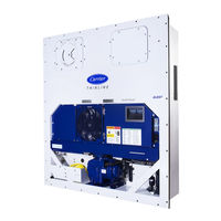
Carrier Transicold 69NT40-561-199 Operation And Service Manual (182 pages)
Container Refrigeration Units
Brand:
Carrier
| Category:
Refrigerator
| Size: 6 MB
Table of Contents
Table of Contents
6
Figure Number
23
Description
23
General Description
23
Refrigeration Unit - Front Section
23
Figure 3.1 Refrigeration Unit - Front Section
23
Fresh Air Makeup Vent
24
Evaporator Section
24
Figure 3.2 Evaporator Section
24
Compressor Section
25
Figure 3.3 Compressor Section
25
Air-Cooled Condenser Section
26
Figure 3.4 Air-Cooled Condenser Section
26
Water-Cooled Condenser Section
27
Figure 3.5 Water-Cooled Condenser Section
27
Control Box Section
28
Communications Interface Module
28
Figure 3.6 Control Box Section
28
Refrigeration System Data
29
Electrical Data
29
Table Number
31
Safety and Protective Devices
31
Table 3-1 Safety and Protective Devices
31
Refrigeration Circuit
32
Standard Operation
32
Economized Operation
32
Electronic Expansion Valve
32
Figure 3.7 Refrigeration Circuit Schematic - Standard Operation
33
Figure 3.8 Refrigeration Circuit Schematic - Standard Operation with Water-Cooled Condenser
34
Figure 3.9 Refrigeration Circuit Schematic - Economized Operation
35
Microprocessor
37
Temperature Control Microprocessor System
37
Figure 4.1 Temperature Control System
37
Display Module
38
Figure 4.2 Keypad
38
Keypad
38
Table 4-1 Keypad Function
38
Controller
39
Controller Software
39
Figure 4.3 Display Module
39
Configuration Software (Cnf Variables)
40
Operational Software (CD Function Codes)
40
Modes of Operation
40
Figure 4.4 Control Module
40
Perishable Heating
41
Perishable Idle, Air Circulation
41
Perishable Mode Temperature Control
41
Perishable Pulldown
41
Perishable Steady State
41
Start up - Compressor Bump Start
41
Start up - Compressor Phase Sequence
41
Figure 4.5 Controller Operation - Perishable Mode
42
Perishable Dehumidification
42
Perishable Dehumidification - Bulb Mode
43
Perishable Economy
43
Perishable Mode Cooling - Sequence of Operation
43
Figure 4.6 Perishable Mode Cooling
44
Perishable Mode Heating - Sequence of Operation
44
Figure 4.7 Perishable Mode Heating
45
Frozen Idle Mode
45
Frozen Mode - Temperature Control
45
Frozen Steady State
45
Perishable Mode - Trim Heat
45
Figure 4.8 Controller Operation - Frozen Mode
46
Frozen "Heat" Mode
46
Frozen Economy Mode
46
Frozen Mode Cooling - Sequence of Operation
46
Defrost
47
Figure 4.9 Frozen Mode
47
Automatic Defrost
48
Defrost Initiation
48
Defrost Interval
49
Defrost Related Settings
49
Figure 4.10 Defrost
49
Protection Modes of Operation
50
Evaporator Fan Operation
50
Failure Action
50
Generator Protection
50
Compressor High Temperature, Low Pressure Protection
50
Perishable Mode - System Pressure Regulation
50
Condenser Fan Override
51
Quest - Ccpc
51
Controller Alarms
51
Pre-Trip Diagnostics
52
Datacorder
52
Description
52
Datacorder Software
53
Sensor Configuration (Dcf02)
54
Logging Interval (Dcf03)
54
Thermistor Format (Dcf04)
54
Figure 4.11 Standard Configuration Download Report
55
Table 4-2 Datacorder Configuration Variables
55
Sampling Type (Dcf05 & Dcf06)
56
Alarm Configuration (Dcf07 - Dcf10)
56
Datacorder Power up
56
Table 4-3 Datacorder Standard Configurations
56
Pre-Trip Data Recording
57
Datacorder Communications
57
Figure 4.12 Datareader
57
USDA Cold Treatment
58
USDA Cold Treatment Procedure
58
Datacorder Alarms
59
ISO Trip Header
60
Controller Configuration Variables
60
Table 4-4 Controller Configuration Variables
60
4.10 Controller Function Codes
61
Table 4-5 Controller Function Codes
61
Figure 4.13 Alarm Troubleshooting Sequence
72
4.11 Controller Alarm Indications
73
Table 4-6 Controller Alarm Indications
73
4.12 Controller Pre-Trip Test Codes
82
Table 4-7 Controller Pre-Trip Test Codes
82
Table 4-8 Datacorder Function Code Assignments
89
Table 4-9 Datacorder Pre-Trip Result Records
90
Table 4-10 Datacorder Alarm Indications
91
Operation
93
Inspection (before Loading)
93
Connect Power
93
Connection to 380 / 460 VAC Power
93
Connection to 190 / 230 VAC Power
93
Adjust Fresh Air Makeup Vent
94
Upper Fresh Air Makeup Vent
94
Figure 5.1 Autotransformer
94
Lower Fresh Air Makeup Vent
95
Figure 5.2 Upper Fresh Air Make up Flow Chart
95
Vent Position Sensor
96
Eautofresh Operation
96
Eautofresh Pre-Trip Inspection
97
Eautofresh Start-Up Procedure
97
Eautofresh Modes of Operation
97
Connect Water-Cooled Condenser
98
Water-Cooled Condenser with Water Pressure Switch
98
Water-Cooled Condenser with Condenser Fan Switch
99
Connect Remote Monitoring Receptacle
99
Starting and Stopping Instructions
99
Starting the Unit
99
Stopping the Unit
100
Start-Up Inspection
100
Physical Inspection
100
Check Controller Function Codes
100
Start Temperature Recorder
100
Complete Inspection
100
Pre-Trip Diagnosis
100
Prior to Starting a Pre-Trip
101
Starting a Pre-Trip
101
Displaying Pre-Trip Test Results
102
5.10 Probe Diagnostics
102
5.11 Emergency Bypass Operation
103
Automatic Cold Treatment (Option)
104
Figure 5.3 Diagram of Emergency Bypass Connections
104
Automatic Setpoint Change (Asc)
106
Troubleshooting
107
Unit will Not Start or Starts then Stops
107
Unit Operates Long or Continuously in Cooling
107
Unit Runs but Has Insufficient Cooling
108
Unit will Not Heat or Has Insufficient Heating
108
Unit will Not Terminate Heating
108
Unit will Not Defrost Properly
108
Abnormal Pressures
109
Abnormal Noise or Vibrations
109
Microprocessor Malfunction
110
6.10 no Evaporator Air Flow or Restricted Air Flow
110
6.11 Eautofresh Not Operating
110
6.12 Electronic Expansion Valve Malfunction
110
6.13 Autotransformer Malfunction
111
6.14 Water-Cooled Condenser or Water Pressure Switch
111
6.15 Compressor Operating in Reverse
111
6.16 Abnormal Temperatures
112
6.17 Abnormal Currents
112
Service
113
Section Layout
113
Manifold Gauge Set
113
Figure 7.1 Manifold Gauge Set
113
Service Connections
114
Figure 7.2 R-134A Manifold Gauge/Hose Set
114
Connecting the Manifold Gauge Set
115
Figure 7.3 Service Valve
115
Removing the Manifold Gauge Set
115
Pump down the Unit
116
Refrigerant Leak Checking
116
Evacuation and Dehydration
117
General
117
Preparation
117
Evacuate and Dehydrate - Complete System
117
Figure 7.4 Refrigeration System Service Connections
117
Evacuate and Dehydrate - Partial System
118
Refrigerant Charge
118
Checking the Refrigerant Charge
118
Figure 7.5 Compressor Kit
120
Figure 7.6 High Pressure Switch Testing
122
Figure 7.7 Water-Cooled Condenser Cleaning, Forced Circulation
125
Figure 7.8 Water-Cooled Condenser Cleaning - Gravity Circulation
126
Figure 7.9 5+1 Heater Arrangement - Omega Heater
128
Figure 7.10 Evaporator Fan Assembly
129
Figure 7.11 Electronic Expansion Valve
131
Figure 7.12 Coil View of Economizer Solenoid Valve (ESV)
131
Figure 7.13 Economizer Expansion Valve
132
Figure 7.14 View of Digital Unloader Valve (DUV) Assembly
133
Figure 7.15 Autotransformer
135
Table 7-1 Valve Override Control Displays
135
Table 7-2 Test Point Descriptions
136
Figure 7.16 Controller Section of the Control Box
137
Table 7-3 Sensor Resistance - AMBS, DTS, ETS, RRS, RTS, SRS, STS
142
Table 7-4 Sensor Resistance - Primeline CPDS
143
Figure 7.17 Sensor Types
144
Figure 7.18 Sensor and Cable Splice
144
Figure 7.19 Supply Sensor Positioning
145
Sensor DTS Reinstallation
146
Sensor CPDS Reinstallation
146
Figure 7.20 Return Sensor Positioning
146
Figure 7.21 Evaporator Temp Sensor Positioning
146
Vent Position Sensor (Vps)
147
Upper VPS
147
Lower VPS
147
Figure 7.22 Compressor Discharge Temperature Sensor
147
Humidity Sensor (Hs)
148
Checking the Operation of the Humidity Sensor
148
7.27 Eautofresh Service
150
Servicing the Eautofresh Air Filter
150
Checking Eautofresh Drive System
150
Figure 7.23 Stepper Components
150
Checking the Controller
151
Figure 7.24 Jumper Assembly
151
Servicing the Eautofresh Drive System
152
7.28 Electronic Partlow Temperature Recorder
153
Figure 7.25 Motor Cup Replacement
153
Replacing the Recorder
154
Figure 7.26 Electronic Partlow Temperature Recorder
154
Recalibrating the Temp Recorder to Zero
155
7.29 Maintenance of Painted Surfaces
155
7.30 Communications Interface Module Installation
155
Figure 7.27 Communications Interface Installation
155
Installing the Module
156
Table 7-5 R-134A Refrigerant Pressure Temperature Chart
156
Table 7-6 Recommended Bolt Torque Values (Dry, Non-Lubricated for 18-8 Stainless Steel)
160
Electrical Wiring Schematics
161
Introduction
161
Figure 8.1 Legend for Standard Unit Configuration
162
Figure 8.2 Schematic Diagram for Standard Unit Configuration
163
Figure 8.3 Legend for Configuration with Available Options
164
Figure 8.4 Schematic Diagram for Configuration with Available Options
165
Figure 8.5 Legend for Configuration with Eautofresh and Emergency Bypass Options
166
Figure 8.6 Schematic Diagram for Configuration with Eautofresh and Emergency Bypass Options
167
Figure 8.7 Schematic and Wiring Diagram for Upper Vent Position Sensor (VPS) Option
168
Figure 8.8 Schematic and Diagram for Lower Vent Position Sensor (VPS) Option
169
Figure 8.9 Unit Wiring Diagram for Standard Unit Configuration with 3-Phase Condenser Fan Motors
170
Figure 8.10 Unit Wiring Diagram for Single Phase Condenser Fan Motor and Optional Heater
172
Figure 8.11 Unit Wiring Diagram for Configuration with Eautofresh and Emergency Bypass Options
174
Index
177
Advertisement
Carrier Transicold 69NT40-561-199 Operation And Service (136 pages)
Container Refrigeration Units
Brand:
Carrier
| Category:
Freezer
| Size: 2 MB
Table of Contents
Table of Contents
8
Table 2−1 Safety and Protective Devices
24
Table 3−1 Keypad Function
29
Vent Position Sensor (Vps)
41
Table 3−2 Datacorder Configuration Variables
41
Table 3−3 Datacorder Standard Configurations
43
Table 3−4 Controller Configuration Variables
46
Table 3−5 Controller Function Codes
47
Table 3−6 Controller Alarm Indications
56
Table 3−7 Controller Pre-Trip Test Codes
64
Table 3−8 Datacorder Function Code Assignments
70
Table 3−9 Datacorder Pre-Trip Result Records
71
Table 3−10 Datacorder Alarm Indications
72
Table 6−1 Valve Override Control Displays
100
Temperature Sensor Service
104
Sensor Checkout Procedure
104
Table 6−2 Sensor Resistance
105
Table 6−3 Sensor Resistance (CPDS)
106
Sensor Replacement
107
Sensor Re-Installation
107
Eautofresh SERVICE
110
Servicing the Eautofresh Air Filter
110
Checking Eautofresh Drive System
110
Checking the Controller
111
Servicing the Eautofresh Drive System
111
Electronic Partlow Temperature Recorder
113
Maintenance of Painted Surfaces
114
Communications Interface Module Installation
114
Table 6−4 R-134A Temperature - Pressure Chart
115
Table 6−5 Recommended Bolt Torque Values
116
Electrical Wiring Schematics
117
Advertisement
Related Products
Carrier 69NT40-561-019
Carrier 69NT40-561-399
Carrier 69NT40-561-300
Carrier Transicold 69NT40-561-001
Carrier PrimeLINE 69NT40-561
Carrier 69NT40-511-199
Carrier 69NT40--541--200 TO 299
Carrier 69NT40-541-508
Carrier 69NT40-551-599
Carrier 69NT40-511-359
Carrier Categories
Air Conditioner
Heat Pump
Furnace
Thermostat
Chiller
More Carrier Manuals
Login
Sign In
OR
Sign in with Facebook
Sign in with Google
Upload manual
Upload from disk
Upload from URL