
Related Manuals for Carrier 69NT40-551-500


Summary of Contents for Carrier 69NT40-551-500
- Page 1 Container Refrigeration OPERATION AND SERVICE 69NT40--551--500 TO 599 Container Refrigeration Units T--334 Rev B Downloaded from ManualsNet.com search engine...
- Page 2 OPERATION AND SERVICE MANUAL CONTAINER REFRIGERATION UNIT Models 69NT40- -551- -500 to 599 Downloaded from ManualsNet.com search engine...
- Page 3 TABLE OF CONTENTS PARAGRAPH NUMBER Page GENERAL SAFETY NOTICES ............Safety--1 FIRST AID .
-
Page 4: Table Of Contents
TABLE OF CONTENTS - - Continued PARAGRAPH NUMBER Page 2.1.3 Evaporator Section ..............2--2 2.1.4 Compressor Section . - Page 5 TABLE OF CONTENTS - - Continued PARAGRAPH NUMBER Page 3.6.3 Sensor Configuration (dCF02) ............3--8 3.6.4 Logging Interval (dCF03) .
- Page 6 TABLE OF CONTENTS - - Continued PARAGRAPH NUMBER Page TROUBLESHOOTING ............... . . 5- -1 UNIT WILL NOT START OR STARTS THEN STOPS .
- Page 7 TABLE OF CONTENTS - - Continued PARAGRAPH NUMBER Page 6.12 EXPANSION VALVES ..............6--12 6.12.1 Checking Superheat .
- Page 8 LIST OF ILLUSTRATIONS FIGURE NUMBER Page Figure 2--1 Refrigeration Unit - Front Section ........... . . 2--1 Figure 2--2 Evaporator Section .
- Page 9 LIST OF ILLUSTRATIONS - - Continued FIGURE NUMBER Page Figure 6--22 Supply Sensor Positioning ............6--23 Figure 6--23 Return Sensor Positioning .
- Page 10 SAFETY SUMMARY GENERAL SAFETY NOTICES SPECIFIC WARNING AND CAUTION STATEMENTS To help identify the label hazards on the unit and explain The following general safety notices supplement the level of awareness each one carries, an explanation specific warnings and cautions appearing elsewhere in is given with the appropriate consequences: this manual.
- Page 11 WARNING WARNING With power OFF discharge the capacitor Make sure that the unit circuit breaker(s) before disconnecting the circuit wiring. (CB-1 & CB-2) and the START-STOP switch (ST) are in the “O” (OFF) position before connecting to any electrical power source. WARNING Do not use a nitrogen cylinder without a WARNING...
- Page 12 (every 60 days) with corrosion inhibiting CRC 3-36a or 6-66 or LPS no. 2. CAUTION CAUTION Use only Carrier Transicold approved Polyol Ester Oil (POE) - EAL 32ST compres- sor oil with R-134a. Buy in quantities of one Recorder element capillary tubing may be quart or smaller.
- Page 13 1.1 INTRODUCTION 1.3.2 Dehumidification The unit may be fitted with a humidity sensor. This The Carrier Transicold model 69NT40-551-500 to 599 sensor allows setting of a humidity set point in the series units are of lightweight aluminum frame controller. In dehumidification mode, the controller will construction, designed to fit in the front of a container operate to reduce internal container moisture level.
- Page 14 1.3.12 Autotransformer 1.3.22 Upper Air (Fresh Air Make Up) The unit may be fitted with an upper fresh air makeup An autotransformer may be provided to allow operation assembly. The fresh air makeup assembly is available 190/230, 3-phase, 50/60 power. with a vent positioning sensor (VPS) and may also be autotransformer raises the supply voltage to the fitted with screens.
-
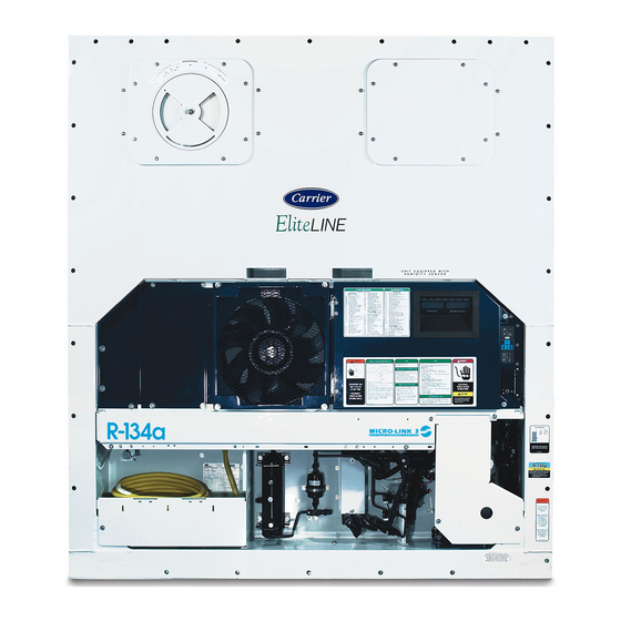
Page 15: Figure 2--1 Refrigeration Unit - Front Section
SECTION 2 DESCRIPTION 2.1 GENERAL DESCRIPTION 2.1.2 Fresh Air Makeup Vent 2.1.1 Refrigeration Unit - Front Section The function of the upper or lower makeup air vent is to The unit is designed so that the majority of the provide ventilation for commodities that require fresh air components are accessible from the front, see circulation. -
Page 16: Evaporator Section
2.1.3 Evaporator Section The evaporator fans circulate air through the container by pulling it in the top of the unit, directing it through the The evaporator section (Figure 2--2) contains the return evaporator coil, where it is heated or cooled, and temperature sensor, humidity sensor, thermostatic discharging it at the bottom. -
Page 17: Compressor Section
2.1.4 Compressor Section The supply temperature sensor, supply recorder sensor and ambient sensor are located to the left of the compressor. The compressor section includes the compressor (with high pressure switch), a discharge pressure transducer Suction modulation valve is located behind the control and the suction pressure transducers. -
Page 18: Air-Cooled Condenser Section
2.1.5 Air-Cooled Condenser Section liquid injection valve, economizer expansion valve, and economizer solenoid valve. The air-cooled condenser section (Figure 2--4) consists of the condenser fan, condenser coil, receiver, sight The condenser fan pulls air through the bottom of the glass/moisture indicator, liquid line service valve, filter coil and discharges it horizontally through the drier, fusible plug, economizer, unloader solenoid valve, condenser fan grille. -
Page 19: Water-Cooled Condenser Section
2.1.6 Water-Cooled Condenser Section liquid injection valve (LIV), economizer expansion valve (EEV), economizer solenoid valve (ESV), and The water-cooled condenser section (Figure 2--5) moisture/liquid indicator. consists of a water-cooled condenser, sight glass, rupture disc, filter drier, water couplings, water pressure The water cooled condenser replaces the standard unit switch, economizer, unloader solenoid valve (USV), receiver. -
Page 20: Control Box Section
2.1.7 Control Box Section 2.1.8 Communications Interface Module The control box (Figure 2--6) includes: the manual The communications interface module is a slave operation switches, circuit breaker (CB-1), compressor, module that allows communication with a master central fan and heater contactors, control power transformer, monitoring station. -
Page 21: Refrigeration System Data
2.2 REFRIGERATION SYSTEM DATA Model RSH105 Weight (Dry) 46.5 kg (103 lb) a. Compressor/Motor Approved Oil Mobil - 32ST Assembly Oil Charge 2957 ml (100 ounces) The oil level range, with the compressor off, Oil Sight Glass should be visible within the sight glass. Verify at -18C b. -
Page 22: Electrical Data
2.3 ELECTRICAL DATA CB-1 Trips at 29 amps CB-2 (50 amp) Trips at 62.5 amps a. Circuit Breaker CB-2 (70 amp) Trips at 87.5 amps b. Compressor Full Load Amps (FLA) 13 amps @ 460 VAC Motor 380 VAC, Single Phase, 460 VAC, Single Phase, 50 Hz 60 Hz... -
Page 23: Safety And Protective Devices
Table 2.3 - Continued Control Circuit 7.5 amps (F3A,F3B) Controller/DataCORDER 5 amps (F1 & F2) g. Fuses Emergency Bypass 10 amps (FEB) Emergency Defrost 5 amps (FED) Electrical Output 0.5 VDC to 4.5 VDC over 90 degree range h. Vent Positioning Supply Voltage 5 VDC +/- 10% Sensor... -
Page 24: Table 2--1 Safety And Protective Devices
Table 2- -1 Safety and Protective Devices UNSAFE CONDITION DEVICE DEVICE SETTING Circuit Breaker (CB-1) - Manual Reset Trips at 29 amps (460 VAC) Trips at 62.5 amps (230 Excessive current draw Circuit Breaker (CB-2, 50 amp) - Manual Reset VAC) Trips at 87.5 amps (230 Circuit Breaker (CB-2, 70 amp) - Manual Reset... -
Page 25: Refrigeration Circuit
2.5 REFRIGERATION CIRCUIT 2.5.2 Economized Operation In the economized mode the frozen and pull down 2.5.1 Standard Operation capacity of the unit is increased by subcooling the liquid refrigerant entering the evaporator expansion valve. Starting at the compressor, (see Figure 2--7, upper Overall efficiency is increased because the gas leaving schematic) the suction gas is compressed to a higher the economizer enters the compressor at a higher... -
Page 26: Figure 2--7 Refrigeration Circuit Schematic - Standard Operation
STANDARD OPERATION WITH RECEIVER EVAPORATOR TXV BULB EVAPORATOR CONDENSER TXV BYPASS VALVE ECONOMIZER TXV BULB DISCHARGE SERVICE VALVE SIGHT GLASS ECONOMIZER ECONOMIZER CONNECTION FILTER FUSIBLE PLUG DRIER ECONOMIZER MOISTURE INDICATOR SUCTION SERVICE LIQUID LINE VALVE SERVICE VALVE RECEIVER COMPRESSOR STANDARD OPERATION WITH WATER COOLED CONDENSER EVAPORATOR TXV BULB EVAPORATOR... -
Page 27: Figure 2--8 Refrigeration Circuit Schematic - Economized Operation
ECONOMIZER CONNECTION ECONOMIZER ECONOMIZER LIQUID LINE SERVICE VALVE LIQUID ECONOMIZER RECEIVER PRESSURE Figure 2- -8 Refrigeration Circuit Schematic - Economized Operation ECONOMIZER CONNECTION SUCTION SERVICE VALVE RECEIVER SUCTION ECONOMIZER PRESSURE Figure 2- -9 Refrigeration Circuit Schematic - Unloaded Operation 2--13 T-334 Downloaded from ManualsNet.com... -
Page 28: Microprocessor
SECTION 3 MICROPROCESSOR 3.1 TEMPERATURE CONTROL MICROPRO- operating parameters cargo temperature CESSOR SYSTEM parameters for future retrieval. Coverage of the temperature control software begins with paragraph 3.2. The temperature control Micro-Link 3 microprocessor Coverage of the DataCORDER software is provided in system (see Figure 3--1) consists of a key pad, display paragraph 3.6. -
Page 29: Key Pad
3.1.1 Key Pad NOTE The controlling probe in the perishable range The key pad (Figure 3--2) is mounted on the right-hand will be the SUPPLY air probe and the controlling side of the control box. The key pad consists of eleven probe in the frozen range will be the RETURN push button switches that act as the user’s interface with the controller. -
Page 30: Controller
3.2 CONTROLLER SOFTWARE The controller software is a custom designed program that is subdivided into configuration software and COOL HEAT DEFROST IN RANGE ALARM SUPPLY RETURN operational software. The controller software performs the following functions: a. Control supply or return air temperature to required limits, provide modulated refrigeration operation, economized operation, unloaded operation, electric SETPOINT/Code... -
Page 31: Modes Of Operation
Figure 3- -4 Control Module The programming is divided into function codes. Some ice on the evaporator coil. In this way, defrosts are of the codes are read only while the remaining codes scheduled to occur only when necessary. may be user configured. The value of the user Once set point has been reached in frozen operation, configurable codes can be assigned in accordance with the automatic selection will set the time interval to... -
Page 32: Perishable Mode - Economy
However, pressure and current limit functions may 2. The unit is in the perishable steady state mode and restrict the valve if either exceeds the preset value. supply air temperature is less than 0.25C above set point. In perishable-pulldown mode, if return temperature is 3. -
Page 33: Perishable - System Pressure Regulation
thermostat settings. (Refer to paragraph NO TAG.) The When temperature drops to set point minus 0.2C and temperature at which the defrost termination thermostat the compressor has run for at least five minutes, the unit will be considered “open” may be changed [in 0.1C will transition to the frozen idle mode. - Page 34 compressor on line. An example is alarm code “LO,” ty, economy, dehumidification and bulb (low main voltage), when a voltage drop of over 25% mode must be reactivated. occurs, an indication is given on the display, but the unit will continue to run. When an Alarm Occurs: a.
-
Page 35: Datacorder
ISO Trip Header (When entered via Interrogation configuration to generic and selecting which data points program) to record may be done using the Carrier Transicold Data Economy Mode Start and End Retrieval Program. “Auto 1/Auto 2/Auto 3” Pre-Trip Start and End Bulb Mode Start 1. -
Page 36: Logging Interval (Dcf03)
3. Frequency 19. Suction pressure transducer 4. Humidity 20. Condenser pressure transducer 5. Phase A current 21. Vent position sensor (VPS) 6. Phase B current 3.6.4 Logging Interval (dCF03) 7. Phase C current 8. Main voltage The user may select four different time intervals 9. -
Page 37: Figure 3--5 Standard Configuration Download Report
Raw Data Report for ABC1234567 May 31, 2001 to Jun 04, 2001 System Configuration at the Time of Interrogation: Interrogated On Sept 05, 2001 Extracted by DataLINE Rev 1.0.0 Controller Software: 5120 Controller Serial #: 04163552 Bill of Lading #: 1 Origin: Origin Date: Destination:... -
Page 38: Sampling Type (Dcf05 & Dcf06)
3.6.8 DataCORDER Power-Up a. DataReader The DataCORDER may be powered up in any one of The Carrier Transicold Data Reader (see Figure 3--6) is four ways: a simple to operate handheld device designed to extract 1. Normal AC power: The DataCORDER is powered data from the DataCORDER and upload it to a PC. -
Page 39: Usda Cold Treatment
Exposing infested fruit to temperatures of 2.2C (36F) or below for specific periods results in the mortality of the DataReader various stages of this group of insects. In response to the demand to replace fumigation with this environmentally sound process, Carrier has integrated Cold Treatment capability into microprocessor system. -
Page 40: Datacorder Alarms
e. If no alarms are active, the Alarm Queue may be Place in pulp of the product located next Sensor 1 cleared. The exception to this rule is the DataCORD- to the return air intake. ER Alarm Queue Full alarm (AL91) , which does not Place in pulp of the product five feet have to be inactive in order to clear the alarm list. -
Page 41: Table 3--4 Controller Configuration Variables
Table 3- -4 Controller Configuration Variables (Sheet 1 of 2) CONFIGURATION TITLE DEFAULT OPTION NUMBER CnF01 Bypass Valve Enable CnF02 Evaporator Fan Speed dS (Dual) SS (Single) CnF03 Control Sensors FOUr duAL CnF04 Dehumidification Mode CnF05 Reserved for future use ----- CnF06 Condenser Fan Speed Select... - Page 42 Table 3- -4 Controller Configuration Variables (Sheet 2 of 2) CONFIGURATION TITLE DEFAULT OPTION NUMBER CnF41 Lower DTT Setting CnF42 Auto Pre-trip Start CnF47 Fresh Air Vent Position Sensor UPP,LOW,CUStOM CnF48 CFS Override CnF49 DataCORDER Configuration Restore CnF50 Enhanced Bulb Mode Selection Bulb, dEHUM CnF51 Timed Defrost Disable...
-
Page 43: Table 3--5 Controller Function Codes
Table 3- -5 Controller Function Codes (Sheet 1 of 4) Code TITLE DESCRIPTION Note: If the function is not applicable, the display will read “-----” Display Only Functions Displays the SMV percent open. The right display reads 100% when the valve is Suction Modulation Cd01 fully open. - Page 44 Table 3- -5 Controller Function Codes (Sheet 2 of 4) Compressor Run This code displays the time remaining until the unit goes into defrost (in tenths of Time Remaining an hour). This value is based on the actual accumulated compressor running Cd25 Until Defrost time.
- Page 45 Table 3- -5 Controller Function Codes (Sheet 3 of 4) The current limit is the maximum current draw allowed on any phase at any time. Limiting the unit’s current reduces the load on the main power supply. This is ac- Current Limit complished by reducing the SMV position until current draw is reduced to the set Cd32...
- Page 46 Table 3- -5 Controller Function Codes (Sheet 4 of 4) Code Cd47 is used with optional economy mode. The values are 0.5C-4.0C. The Variable Economy Cd47 default is 3.0C. If the unit is not configured for economy mode, “----” will be dis- Temperature Setting played.
-
Page 47: Table 3--6 Controller Alarm Indications
Table 3- -6 Controller Alarm Indications (Sheet 1 of 4) Code TITLE DESCRIPTION Alarm 05 is triggered if the controller detects continuous Manual Defrost Switch Manual Defrost AL05 action for 5 minutes or more. The alarm will only trigger off when the unit is pow- Switch Failure er cycled. - Page 48 Table 3- -6 Controller Alarm Indications (Sheet 2 of 4) Alarm 21 is triggered by one of the fuses (F1/F2) being opened on 18 VAC power supply to the controller. The suction modulation valve (SMV) will be opened and Micro Circuit Fuse AL21 Open (18 VAC) current limiting is halted.
- Page 49 Table 3- -6 Controller Alarm Indications (Sheet 3 of 4) Alarm 53 is caused by the battery pack charge being too low to provide sufficient power for battery-backed recording. If this alarm occurs on start up, allow a unit AL53 Battery Pack Failure fitted with rechargeable batteries to operate for up to 24 hours to charge re- chargeable batteries sufficiently to deactivate the alarm.
- Page 50 Table 3- -6 Controller Alarm Indications (Sheet 4 of 4) Suction Pressure AL66 Alarm 66 is triggered if a suction pressure transducer is out of range. Transducer Failure Alarm 67 is triggered by a humidity sensor reading outside the valid range of 0% Humidity Sensor to 100% relative humidity.
-
Page 51: Table 3--7 Controller Pre-Trip Test Codes
Table 3- -7 Controller Pre-Trip Test Codes (Sheet 1 of 4) Code TITLE DESCRIPTION NOTE “Auto” or “Auto1” menu includes the: P0, P1, P2, P3, P4, P5, P6 and rSLts. “Auto2” menu in- cludes P0, P1, P2, P3, P4, P5, P6, P7, P8, P9, P10 and rSLts. “Auto3” menu includes P0, P1, P2, P3, P4, P5, P6, P7 and P8. - Page 52 Table 3- -7 Controller Pre-Trip Test Codes (Sheet 2 of 4) Setup: The High Speed Evaporator Fan is turned on, a current draw test is done after 60 seconds. High Speed P4-0 Evaporator Fan Pass/Fail Criteria: Passes if change in current draw is within the range speci- fied.
- Page 53 Table 3- -7 Temperature Controller Pre-Trip Test Codes (Sheet 3 of 4) Suction Modulation Suction pressure is measured before and after the valve opens. If suction pres- P6-5 Valve Test sure does not increase, the test fails. Economizer Suction pressure is measured during Steps 4 and 5. If suction pressure does not P6-6 Valve Test increase, the test fails.
- Page 54 Table 3- -7 Temperature Controller Pre-Trip Test Codes (Sheet 4 of 4) Requirements: Test P8-1 must pass for this test to execute. This test is skipped if the DataCORDER is not configured or not available. Setup: A 15 minute timer is started. The unit will be required to minimize control temperature error (supply temperature minus set point) until the timer expires.
-
Page 55: Table 3--8 Datacorder Function Code Assignments
Table 3- -8 DataCORDER Function Code Assignments NOTE Inapplicable Functions Display “-----” To Access: Press ALT. MODE key Code TITLE DESCRIPTION Recorder Supply Current reading of the supply recorder sensor. Temperature Recorder Return Current reading of the return recorder sensor. Temperature USDA 1,2,3 Temper- dC3-5... -
Page 56: Table 3--9 Datacorder Pre-Trip Result Records
Table 3- -9 DataCORDER Pre-Trip Result Records Test TITLE DATA Heater On Pass/Fail/Skip Result, Change in current for Phase A, B and C Heater Off Pass/Fail/Skip Result, Change in currents for Phase A, B and C Pass/Fail/Skip Result, Water pressure switch (WPS) - Open/Closed, Condenser Fan On Change in currents for Phase A, B and C Condenser Fan Off... -
Page 57: Table 3--10 Datacorder Alarm Indications
Table 3- -10 DataCORDER Alarm Indications To Access: Press ALT. MODE key Code No. TITLE DESCRIPTION The supply recorder sensor reading is outside of the range of -50C to 70C (-58F to +158F), or the probe check logic has determined there is a fault Recorder Supply with this sensor. -
Page 58: Operation
SECTION 4 OPERATION 4.1 INSPECTION (Before Starting) 2. Plug the 460 VAC (yellow) cable into a de-energized 380/460 VAC, 3-phase power source. Energize the power source. Place circuit breaker (CB-1) in position WARNING “I” (ON). Close and secure control box door. 4.2.2 Connection To 190/230 VAC Power Beware of unannounced starting of the An autotransformer (Figure 4--1) is required to allow... -
Page 59: Upper Fresh Air Makeup Vent
4.3.1 Upper Fresh Air Makeup Vent b. Reduced Flow for Fresh Air Makeup On some models the air slide is supplied with two Two slots and a stop are designed into the disc for air adjustable air control disks. The fresh air makeup can be flow adjustments. -
Page 60: Connect Water-Cooled Condenser
4.4 CONNECT WATER-COOLED CONDENSER 4.6 STARTING AND STOPPING INSTRUCTIONS The water-cooled condenser is used when cooling WARNING water is available and heating the surrounding air is objectionable, such as in a ship’s hold. If water-cooled operation is desired, connect in accordance with the Make sure that the unit circuit breaker(s) following subparagraphs. -
Page 61: Complete Inspection
4.7.4 Complete Inspection 3. Pre-trip also initiated communications. The operation is the Allow unit to run for five minutes to stabilize conditions same as for the key pad initiation described and perform a pre-trip diagnosis in accordance with the below except that should a test fail, the following paragraph. -
Page 62: Observe Unit Operation
ing the PRE-TRIP key. The unit will then resume nor- If the probe check option is configured for special, the mal operation. If the user decides to terminate a test above criteria are applicable. A defrost with probe check but remain at the test selection menu, the user may will be initiated if 25 of 30 readings or 10 consecutive press the UP ARROW key. -
Page 63: Figure 4--3 Controller Operation - Perishable Mode
RISING FALLING PULL DOWN TEMPERATURE TEMPERATURE +2.5C +2.5C (4.5F) (4.5F) START UNLOADED, MODULATED MODULATED TRANSITION TO COOLING COOLING ECONOMIZED UNLOADED UNLOADED OPERATION +.20C +.20C SET POINT SET POINT AIR CIRCULATION UNLOADED OPERATION -0.20C -0.20C AIR CIRCULATION AIR CIRCULATION -0.5C -0.5C (0.9F) (0.9F) HEATING... -
Page 64: Sequence Of Operation - Perishable Mode Cooling
4.10.2 Sequence of Operation - Perishable Mode f. If the calculation determines cooling is no longer re- Cooling quired, contacts TC and TN are opened to de-ener- gize compressor motor and condenser fan motor. NOTE The cool light is also de-energized. In the Conventional Perishable Mode of Opera- g. -
Page 65: Sequence Of Operation - Frozen Mode Cooling
4.10.4 Sequence of Operation - Frozen Mode Cool- 4.10.5 Sequence of Operation - Defrost The defrost cycle may consist of up to three distinct operations. The first is de-icing of the coil, the second is a. With supply air temperature above set point and de- a probe check cycle and the third is snap freeze. -
Page 66: Emergency Bypass Operation
Defrost may be initiated any time the defrost If controller function code CnF33 is configured to snap temperature sensor reading falls below the controller freeze, the controller will sequence to this operation. defrost termination thermostat set point. Defrost will The snap freeze consists of running the compressor terminate when the defrost temperature sensor reading without the evaporator fans in operation for a period of rises above the defrost termination thermostat set point. -
Page 67: Troubleshooting
SECTION 5 TROUBLESHOOTING REMEDY/ CONDITION POSSIBLE CAUSE REFERENCE SECTION 5.1 UNIT WILL NOT START OR STARTS THEN STOPS External power source OFF Turn on Start-Stop switch OFF or defective Check No power to unit Circuit breaker tripped or OFF Check Autotransformer not connected 4.2.2 Circuit breaker OFF or defective... -
Page 68: Unit Runs But Has Insufficient Cooling
REMEDY/ CONDITION POSSIBLE CAUSE REFERENCE SECTION 5.3 UNIT RUNS BUT HAS INSUFFICIENT COOLING Abnormal pressures Abnormal temperatures 5.15 Abnormal currents 5.16 Controller malfunction Evaporator fan or motor defective 6.15 Shortage of refrigerant 6.3 /6.4 Refrigeration system Suction modulation valve lost track of step count Power cycle Suction modulation valve malfunction 6.18... -
Page 69: Abnormal Pressures (Cooling)
REMEDY/ CONDITION POSSIBLE CAUSE REFERENCE SECTION 5.6 UNIT WILL NOT DEFROST PROPERLY - Continued Manual defrost switch defective Replace Will not initiate defrost manually Defrost temperature sensor open 4.10.5 Initiates but relay (DR) drops Low line voltage Heater contactor or coil defective Replace Initiates but does not defrost Heater(s) burned out... -
Page 70: Controller Malfunction
REMEDY/ CONDITION POSSIBLE CAUSE REFERENCE SECTION 5.9 CONTROLLER MALFUNCTION Defective sensor 6.22 Defective wiring Check Will not control Stepper motor suction modulation valve circuit malfunction 6.18 Low refrigerant charge 6.3 /6.4 5.10 NO EVAPORATOR AIR FLOW OR RESTRICTED AIR FLOW Frost on coil Evaporator coil blocked Dirty coil... -
Page 71: Compressor Operating In Reverse
REMEDY/ CONDITION POSSIBLE CAUSE REFERENCE SECTION 5.14 COMPRESSOR OPERATING IN REVERSE NOTE It is normal for the compressor to run in reverse for 15 seconds when the compressor has been off for 6 hours or more. CAUTION Allowing the scroll compressor to operate in reverse for more than two minutes will result in internal compressor damage. -
Page 72: Service
Pressurized mixtures of air models covered within this manual. The manifold or gases containing oxygen can lead to ex- gauge/hose set is available from Carrier Transicold. plosion. (Carrier Transicold part number 07-00294-00, which includes items 1 through 6, Figure 6--2.) To perform service using the manifold gage/hose set, do the 6.1 SECTION LAYOUT... -
Page 73: Refrigeration System Service-Units With Standard Piping (With Service Valves)
3. Evacuate to 10 inches of vacuum and then charge CAUTION with R-134a to a slightly positive pressure of 0.1 kg/ (1.0 psig). To prevent trapping liquid refrigerant in the 4. Front seat both manifold gauge set valves and dis- manifold gauge set be sure set is brought to connect from cylinder. -
Page 74: Refrigerant Leak Checking
(see gauge. (The pump is available from Carrier Trans- Figure 6--4). Be sure the service hoses are suited for icold, part number 07-00176-11.) evacuation purposes. -
Page 75: Refrigerant Charge
c. The area between the suction modulating valve and a. Connect the gauge manifold to the compressor dis- evaporator expansion valve may not be open to the charge and suction service valves. For units operat- access valves. To ensure evacuation of this area, ing on a water cooled condenser, change over to air check that the suction modulating valve is more than cooled operation. -
Page 76: Figure 6--5 Semi-Hermetic Piping Refrigeration System Service Connections
6.4 REFRIGERATION SYSTEM SERVICE - UNITS WITH SEMI-HERMETIC PIPING (without Ser- vice Valves) 6.4.1 Service Connections The compressor is fitted with access valves at the suction connection, economizer fitting and liquid line fitting to enable servicing of the system. Refrigerant must be removed from system before performing service. - Page 77 In the U.S.A., refer to EPA Sec- displacement) and an electronic vacuum gauge. (The tion 608. pump is available from Carrier Transicold, part number 07-00176-11.) a. Connect the gauge manifold to the liquid and suction access valves. For units operating on a water cooled Additional time may be saved during a complete system condenser, change over to air cooled operation.
-
Page 78: Compressor
6.4.7 Adding Refrigerant to System (Partial e. Remove and discard the rubber gasket that was lo- Charge) cated between the terminal box and the compressor shell. a. Examine the unit refrigerant system for any evidence f. Remove the rotalock fittings from the suction, dis- of leaks. -
Page 79: Figure 6--7 Compressor Lower Mounting
j. The replacement compressor is shipped with an oil p. Place the new Teflon seals (kit items #2 and 3) at the charge of 591ml (20 ounces). Before sliding the new compressor service ports and connect the four ser- compressor in the unit, remove the cap from the oil vice fittings loosely. -
Page 80: Compressor Oil Level
Install a new high pressure switch after verifying CAUTION switch settings. d. Evacuate, dehydrate and recharge. Use only Carrier Transicold approved e. Start unit, verify refrigeration charge and oil level. Polyol Ester Oil (POE) - Mobil 32ST com- pressor oil with R-134a. Buy in quantities of 6.7.2 Checking High Pressure Switch... -
Page 81: Condenser Coil
6.8 CONDENSER COIL (0.08” +/- 0.03”) from the outside of the orifice open- ing. Spin fan by hand to check clearance. The condenser consists of a series of parallel copper g. Close and secure condenser fan screen guard. tubes expanded into copper fins. The condenser coil must be cleaned with fresh water or steam so the air flow 6.10 WATER- -COOLED CONDENSER CLEANING is not restricted. -
Page 82: Figure 6--9 Water-Cooled Condenser Cleaning - Forced Circulation
Summary of Procedure: a. Drain water from condenser tubing circuit. Clean water tubes with Oakite No. 22 to remove mud and slime. b. Flush. c. De-scale water tubes with Oakite No. 32 to remove scale. d. Flush. e. Neutralize. f. Flush. g. -
Page 83: Filter Drier
NOTE 2. Check the moisture-liquid indicator if the indicator shows a high level of moisture, the filter drier should If the condenser cooling water is not being used be replaced. as drinking water or is not re-circulated in a b. To Replace Filter Drier closed or tower system, neutralizing is not nec- essary. -
Page 84: Valve Replacement
c. Connect an accurate gauge to the service port direct- ly upstream of the suction modulating valve d. Set the temperature set point to -18C (0F), and run unit until conditions stabilize. Partially block the con- denser airflow with cardboard or similar material and raise the discharge pressure to above 175 psig (12 bar). -
Page 85: Evaporator Heater Replacement
1. Copper Tube 2. Bi-metallic Tube 3. Braze Rod 4. Use of a wet cloth is (Apply heat for 10-15 sec- Connection (Apply heat for (’Sil-Phos” = 5.5% Silver, not necessary due to rapid onds) 2-5 seconds) 6% Phosphorus) heat dissipation of the bi-metallic connections Figure 6- -14 Hermetic Thermostatic Expansion Valve Brazing Procedure f. -
Page 86: Evaporator Fan And Motor Assembly
6.15.1 Replacing The Evaporator Fan Assembly WARNING Always turn OFF the unit circuit breakers (CB-1 & CB-2) and disconnect main power supply before working on moving parts. a. Remove upper access panel (see Figure 2--2) by removing mounting bolts and TIR locking device. Reach inside of unit and remove the Ty-Rap securing the wire harness loop. -
Page 87: Assemble The Evaporator Fan Assembly
6.15.3 Assemble The Evaporator Fan Assembly 6.16.2 Removing The Capacitor a. Assemble the motor and plastic spacer onto the stator. WARNING Make sure power to the unit is OFF and NOTE power plug disconnected before removing When removing the black nylon evaporator fan capacitor(s). -
Page 88: Table 6--2 Valve Override Control Displays
take place immediately. If the timer is not active, Press the ENTER key and SELCt will appear in the changes will not take place for a few seconds after the left display. timer is started. When the timer times out, override c. -
Page 89: Suction Modulation Valve
6.18 SUCTION MODULATION VALVE The SMA-12 portable stepper drive tester (Carrier Transicold part number 07-00375-00) is a battery On start up of the unit, the valve will reset to a known operated stepper drive which will open and close the open position. -
Page 90: Controller
TP 9 requires handling and removal of a module. a. Obtain a grounding wrist strap (Carrier Transicold This test point is the chassis (unit frame) ground part number 07-00304-00) and a static dissipation connection. -
Page 91: Controller Programming Procedure
6.20.3 Controller Programming Procedure b. Procedure for loading Configuration Software: 1. Turn unit OFF using start-stop switch (ST). To load new software into the module, the programming card is inserted into the programming/software port. 2. Insert software/programming PCMCIA card contain- ing the following (example) files into the program- ming/software port. -
Page 92: Vent Position Sensor Service
6.22 TEMPERATURE SENSOR SERVICE tions 14, 13, 11. Procedures for service of the Return Recorder, Return d. Using Driver Bit, Carrier Transicold part number Temperature, Supply Recorder, Supply Temperature, 07--00418--00, remove the 4 screws securing the dis- Ambient, Defrost Temperature, Compressor Discharge play module to the control box. -
Page 93: Sensor Replacement
Table 6- -3 Sensor Temperature/Resistance Chart (+/-.002%) Temperature Resistance (Ohms) AMBS, CPSS, CPDS DTS, RTS, RRS, STS, SRS Mounting Stud Type 177,000 1,770,000 130,400 1,340,000 97,070 970,700 72,900 729,000 55,330 553,000 43,200 423,300 32,650 326,500 Bulb Type 25,390 253,900 19,900 199,000 1. -
Page 94: Figure 6--22 Supply Sensor Positioning
CAUTION Do not allow moisture to enter wire splice area as this may affect the sensor resis- tance. m. Position sensor in unit as shown in Figure 6--22 and re-check sensor resistance. n. Reinstall sensor, refer to paragraph 6.22.3. NOTE The P5 Pre-Trip test must be run to inactivate 1. - Page 95 a. Turn power to the unit OFF. NOTE Failure to press the change chart button, when b. Open the recorder door (item 1, see Figure 6--24). changing a chart with the power OFF, may result in the chart advancing when power is c.
-
Page 96: Figure 6--24 Electronic Partlow Temperature Recorder
Connector Recorder Door Calibration Button Change Chart (Located underneath) Button Mounting Screws, Recorder Box #10-24 x 7/16 inches long Pen Tip Hold Down Tab Stylus Arm Chart Retaining Nut Figure 6- -24 Electronic Partlow Temperature Recorder 6.23.3 Adjusting the Recorder Stylus NOTE Use chart CTD part number 09-00128-00 (F) Proper stylus force upon the chart paper is important. -
Page 97: Maintenance Of Painted Surfaces
An adhesive sealant must be used to make the repair watertight. The adhesive sealant c. Press the calibration button and the pen will position (Sikaflex 221) is included in Crack Repair Kit Carrier itself to the correct temperature reading. Transicold... -
Page 98: Figure 6--25 Door Hinge Repair
Static Mixing Tube (Loctite 983440) 07-00390-00 . . . Instruction Sheet 98-02338-00 Note: Insert repair procedures require use of an Application Gun, Carrier part number 07-00391-00 (Loctite 983435) Table 6- -6 Drill Information Item Insert part number Drill size and depth 34- 06231- 01 10.3 mm x 17.8 mm deep (0.404 in. -
Page 99: Figure 6--26 Insert Location
Figure 6- -26 Insert Location T-334 6--28 Downloaded from ManualsNet.com search engine... -
Page 100: Communications Interface Module Installation
Units that have been factory provisioned for installation 5.2 in-lbs of a communication interface module (CIM) have the 9.6 in-lbs required wiring installed. If the unit is not factory 20 in-lbs provisioned, a provision wiring kit (Carrier Transicold 23 in-lbs 75 in-lbs part number 76-00685-00) must installed. -
Page 101: Table 6--8 R-134A Temperature - Pressure Chart
Table 6- -8 R-134a Temperature - Pressure Chart Temperature Vacuum Temperature Pressure “/hg cm/hg kg/cm psig kg/cm 14.6 49.4 37.08 0.49 24.5 168.9 1.72 1.69 26.1 180.0 1.84 1.80 12.3 41.6 31.25 0.42 27.8 191.7 1.95 1.92 32.8 24.64 0.33 29.6 204.1 2.08... -
Page 102: Electrical Wiring Schematics
SECTION 7 ELECTRICAL WIRING SCHEMATICS 7.1 INTRODUCTION This section contains the Electrical Schematics and Wiring Diagrams. The diagrams are presented as follows: Figure 7--1 provides the legend for use with Figure 7--2, the schematic diagram for units with single--phase motor, normal evaporator fan capability, and Figure 7--3, the schematic diagram for units with single--phase motor, single evaporator fan capability. - Page 103 LEGEND SYMBOL DESCRIPTION (Normal Schematic Location) SYMBOL DESCRIPTION (Normal Schematic Location) [Single Evaporator Fan Schematic Location] [Single Evaporator Fan Schematic Location] AMBS AMBIENT SENSOR (C-21) [C-23] COMPRESSOR PHASE CONTACTOR (L-8, M-7, P-1) [L-12, M-11, N-1] BYPASS MODULE [J8, J9, J10, J11, P18] COMPRESSOR PHASE CONTACTOR CONTROLLER (H-19) [K-21] (L-7, M-8, P-2) [L-11, M-12, N-2]...
-
Page 104: Figure 7--2 Schematic Diagram - Single Phase, Normal Evaporator Fan Capability
FOR VPS, see Figure 7- -8 Figure 7- -2 SCHEMATIC DIAGRAM - Single Phase, Normal Evaporator Fan Capability T-334 7--3 Downloaded from ManualsNet.com search engine... -
Page 105: Figure 7--3 Schematic Diagram - Single Phase, Single Evaporator Fan Capability
Figure 7- -3 SCHEMATIC DIAGRAM - Single Phase, Single Evaporator Fan Capability T-334 7--4 Downloaded from ManualsNet.com search engine... -
Page 106: Figure 7--4 Legend -- Three--Phase Evaporator Fan Motor
LEGEND SYMBOL DESCRIPTION SYMBOL DESCRIPTION AMBS AMBIENT SENSOR (C-21) LIQUID INJECTION SOLENOID VALVE (K-10) UNIT PHASE CONTACTOR (L-1, M-6) CONTROLLER (J-19) UNIT PHASE CONTACTOR (L-3, M-7) CIRCUIT BREAKER - 460 VOLT (F-1) PHYSICAL EARTH-GROUND (F-2) CONDENSER FAN CONTACTOR (M-11, P-6) USDA PROBE RECEPTACLE (E-21, L-22, M-22) COMPRESSOR CONTACTOR (M- -7, P- -1) CONDENSER FAN MOTOR (T- -6, H-10) -
Page 107: Figure 7--5 Schematic Diagram - Three--Phase Evaporator Fan Motor
Figure 7- -5 SCHEMATIC DIAGRAM - Three- -Phase Evaporator Fan Motor T-334 7--6 Downloaded from ManualsNet.com search engine... -
Page 108: Figure 7--6 Schematic Diagram-Transfresh And Emergency Bypass
SEE FIGURE SEE FIGURE TransFRESH CONTROLLER Main Power From QC1 From KA2 From ECG1 From ECJ1 CONTROLLER LEGEND Emergency Bypass BYPASS MODULE EMERGENCY BYPASS FUSE-EMERGENCY BYPASS FUSE-TransFRESH MANUAL SWITCH SUCTION MODULATING VALVE Figure 7- -6 SCHEMATIC DIAGRAM-TransFRESH and Emergency Bypass (For Single Phase Evaporator Fan Motor Applications) T-334 7--7... -
Page 109: Figure 7--7 Schematic And Wiring Diagram - Electronic Partlow Recorder
LEGEND CHART RECORDER Figure 7- -7 SCHEMATIC AND WIRING DIAGRAM - Electronic Partlow Recorder (For Single Phase Evaporator Fan Motor Applications) T-334 7--8 Downloaded from ManualsNet.com search engine... -
Page 110: Figure 7--8 Schematic And Wiring Diagram - Upper And Lower Vent Position Sensors
LOWER VENT POSITION SENSOR UPPER VENT POSITION SENSOR (SEE NOTE) (SEE NOTE) (SEE NOTE) NOTE: VPS2 TO M1 FOR STANDARD VPS. VPS2 TO T1 FOR UPPER VPS VIEWABLE WHILE UNIT IS ON BATTERY POWER. Figure 7- -8 SCHEMATIC AND WIRING DIAGRAM - Upper and Lower Vent Position Sensors T-334 7--9 Downloaded from... -
Page 111: Figure 7--9 Wiring Diagram - Single Phase, Normal Evaporator Fan Capability
Figure 7-5 for detail Control Box Location Condenser Location Figure 7-5 for detail Figure 7- -9 WIRING DIAGRAM - Single Phase, Normal Evaporator Fan Capability (Sheet 1 of 2) T-334 7--10 Downloaded from ManualsNet.com search engine... - Page 112 Figure 7- -9 WIRING DIAGRAM - Single Phase, Normal Evaporator Fan Capability (Sheet 2 of 2) T-334 7--11 Downloaded from ManualsNet.com search engine...
-
Page 113: Figure 7--10 Wiring Diagram - Normal Evaporator Fan Capability With Bypass Module
Figure 7-5 for detail Control Box Location Condenser Location Figure 7-5 for detail Figure 7- -10 WIRING DIAGRAM - Normal Evaporator Fan Capability with Bypass Module (Sheet 1 of 2) T-334 7--12 Downloaded from ManualsNet.com search engine... - Page 114 Figure 7- -10 WIRING DIAGRAM - Normal Evaporator Fan Capability with Bypass Module (Sheet 2 of 2) T-334 7--13 Downloaded from ManualsNet.com search engine...
-
Page 115: Figure 7--11 Wiring Diagram - Single Phase, Single Evaporator Fan Capability
Figure 7- -11 WIRING DIAGRAM - Single Phase, Single Evaporator Fan Capability (Sheet 1 of 2) T-334 7--14 Downloaded from ManualsNet.com search engine... - Page 116 Figure 7- -11 WIRING DIAGRAM - Single Phase, Single Evaporator Fan Capability (Sheet 2 of 2) T-334 7--15 Downloaded from ManualsNet.com search engine...
-
Page 117: Figure 7--12 Wiring Diagram - Three--Phase Evaporator Fan Motor
Figure 7- -12 WIRING DIAGRAM - Three- -Phase Evaporator Fan Motor (Sheet 1 of 2) T-334 7--16 Downloaded from ManualsNet.com search engine... - Page 118 Figure 7- -12 WIRING DIAGRAM - Three- -Phase Evaporator Fan Motor (Sheet 2 of 2) T-334 7--17 Downloaded from ManualsNet.com search engine...
- Page 119 INDEX Economized Operation, Refrigeration Circuit, 2--11 Air Cooled Condenser Section, 2--4 Electrical Data, 2--8 Alarm, 3--6, 3--10, 3--12, 3--13, 3--19, 3--29 Emergency Bypass, 4--9 Autotransformer, 6--18 Evacuation, 6--3, 6--6 Evaporator, 6--13 Evaporator Fan, 1--2, 3--4, 6--15 Evaporator Section, 2--2 Battery Replacement, 6--21 Expansion Bypass Solenoid Valve, Refrigeration Circuit, 2--11 Expansion Valves, 6--12...
- Page 120 INDEX (Continued) LIV Operation, Refrigeration Circuit, 2--11 Safety and Protective Devices, 2--9 Logging Interval, 3--8 Sampling Type, 3--10 Sensor Configuration, 3--8 Sequence Of Operation, 4--5 Solenoid Valves, 6--14 Manifold Gauge Set, 6--1 Standard Operation, Refrigeration Circuit, 2--11 Microporcessor System, 3--1 Starting, 4--3 Modes Of Operation, 3--4 Stopping, 4--3...
- Page 121 Carrier Corporation Container Products Group P.O. Box 4805 Syracuse, N.Y. 13221 U.S A www.carrier.transicold.com A member of the United Technologies Corporation family. Stock symbol UTX ©2007 Carrier Corporation D Printed in U. S. A. 06/07 Downloaded from ManualsNet.com search engine...
Need help?
Do you have a question about the 69NT40-551-500 and is the answer not in the manual?
Questions and answers