Table of Contents
Advertisement
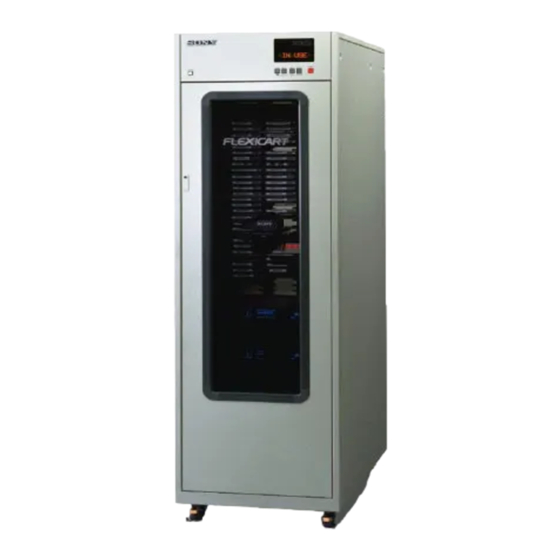
MULTI CASSETTE SYSTEM
FLEXICART
FLEXIBLE CART MACHINE CONSOLE
BFC-1
FLEXIBLE CART MACHINE BIN UNIT
BKFC-8D
BKFC-10B
BKFC-10S
BKFC-21DV
FLEXICART VTR MOUNT KIT
BKFC-52
BKFC-53
BKFC-54
FLEXICART SERIAL INTERFACE BOARD
BKFC-100
FLEXICART DV HAND KIT
BKFC-210
INSTALLATION MANUAL
2nd Edition (Revised 1)
Serial No. 10412 and Higher (BFC-1 for USA/Canada)
Serial No. 20522 and Higher (BFC-1 for Europe)
Advertisement
Table of Contents

Related Manuals for Sony FLEXICART BFC-1


Summary of Contents for Sony FLEXICART BFC-1
- Page 1 MULTI CASSETTE SYSTEM FLEXICART FLEXIBLE CART MACHINE CONSOLE BFC-1 FLEXIBLE CART MACHINE BIN UNIT BKFC-8D BKFC-10B BKFC-10S BKFC-21DV FLEXICART VTR MOUNT KIT BKFC-52 BKFC-53 BKFC-54 FLEXICART SERIAL INTERFACE BOARD BKFC-100 FLEXICART DV HAND KIT BKFC-210 INSTALLATION MANUAL 2nd Edition (Revised 1) Serial No.
- Page 2 ! WARNING This manual is intended for qualified service personnel only. To reduce the risk of electric shock, fire or injury, do not perform any servicing other than that contained in the operating instructions unless you are qualified to do so. Refer all servicing to qualified service personnel.
-
Page 3: Table Of Contents
TABLE OF CONTENTS OUTLINE 4-11. VTR/BIN UNIT INSTALLATION (FOR BETACAM, HDCAM, MPEG IMX and S-VHS VTRs)....4-24 4-11-1. Select BIN Unit and Rack Mount Kit....4-24 1-1. OUTLINE ..............1-1 4-11-2. Installing the Rack Mount Kit and VTR ....4-25 4-11-3. Installing the Bin Unit ...........4-36 4-12. -
Page 5: Outline
Explains the protocol for controlling the Flexicart via the VCC interface. Flexicart is a trademark of Sony Corporation. Betacam SP is a registered trademark of Sony Corporation. VCC stands for Versatile Cart Controller. IBM PC/AT is a registered trademark of International Business Machines Corporation. -
Page 7: Packing
Note: The blank panel (1U) is provided against the space between BIN unit and VTR or VTR and VTR. In the case of the blank panel shortage even the five acces- sories, please contact to sony's service organization. (Sony Part No.: 3-179-787-00) BFC-1... -
Page 8: Bin Unit
2-2. BIN UNIT . BKFC-8D (for D2) . BKFC-10B (for BETACAM, HDCAM, MPEG IMX) . BKFC-10S (for S-VHS) . BKFC-21DV (for DVCAM) BKFC-8D/10B/10S *BKFC-21DV has some differences in package Supplied Accessories: 1 Guide Pin 2 BIN Shutter Plate 3 Screw (+B 5x10) 4 Screw (+PWH 3x6) BFC-1... -
Page 9: Rack Mount Kit
2-3. RACK MOUNT KIT . BKFC-52 ( for DVR-10/20 series, DVR-18/28 series) . BKFC-53 ( for BETACAM, HDCAM, MPEG IMX and S-VHS) : Prepare BKFC-52 having a product code ending with : Prepare BKFC-53 having a product code ending with -1 or higher when installing the DVR-18/28 series -1 or higher when installing the BETACAM UVW VTRs. -
Page 10: Bkfc-100
. BKFC-54 ( for DVCAM) 2-4. BKFC-100 (Optional: for RS-422A serial interface) : Prepare BKFC-54 having a product code ending with -1 or higher when installing the DSR-1600/1800 se- ries VTRs. BKFC-100 2-5. BKFC-210 (Hand conversion kit for DVCAM) Supplied Accessories: Rack Mount (R1) Assy Rack Mount (L1) Assy Guide Plate (R) -
Page 11: Installation Conditions
SECTION 3 INSTALLATION CONDITIONS 3-1. EXTERNAL DIMENSION AND MASS Machines having serial numbers 10169 (for UC) /20091 (for EK) and former have some parts whose shapes and dimensions differ. 3-1-1. External Dimension 527.2 497.4 (600) (1090) 1035 1090 Unit : mm BFC-1... -
Page 12: Mass
3-1-2. Mass 3-2. INSTALLATION CONDITION BFC-1 3-2-1. Operating Condition Console 250 kg +5˚C to +35˚C Operating temperature _40˚C to +60˚C BIN unit Storage temperature BKFC-8D 4.5 kg Humidity 25% to 80% BKFC-10B 4.2 kg BKFC-10S 4.2 kg 3-2-2. Notes on Installing Place BKFC-21DV 2.6 kg Install the console on a flat and firm place. -
Page 13: Door Dimension And Ceiling Height
3-2-3. Door Dimension and Ceiling Height . Door Dimension The minimum door dimensions should be 2000 mm in height, and 700 mm in width. If eye bolts are installed on the top panel, the minimum door height should be 2050 mm. . -
Page 14: Maintenance Space
3-2-4. Maintenance Space To facilitate the maintenance, secure a sufficient space when pulling out the VTR from the console during work. . When the VTR is installed based on a front drawer system: Front side : Approx. 1.0 m Rear side : Approx. -
Page 15: Power Supply
3-3. POWER SUPPLY 3-4. TRANSPORTATION 3-3-1. AC Power Supply The Cart Machine can be lifted and moved with a fork lift in the packing cases, or unpacked. Once unpacked, the console can be Power Supply Voltage: 120/220/230/240 V movable around on the casters which are fitted to the base, if the Power Supply Frequency: 50/60 Hz floor is suficiently even. -
Page 17: Installation And Assembling Procedure
SECTION 4 INSTALLATION AND ASSEMBLING PROCEDURE 4-1. PRECAUTION 4-2-2. Fixture Fixtures to install the cart machine are introduced below. . Wrench (to opposite side: 30 mm) At least two or more persons are required for the cart machine in- stallation to be safe. It is used when adjustment of caster on the console and floor leveler. -
Page 18: Front Door Removal
4-2-3. Front Door Removal It is recommended to remove the front door before installation not to damage it. . Open the front door 1. Rotate the screw counterclockwise (in the direction of the ar- row 1) with hexagonal wrench (to opposite side: 3 mm) and either slide the lock cover. -
Page 19: Installation Flowchart
4-3. INSTALLATION FLOWCHART The installation procedure is shown in the following flowchart. See each section about the detail. START 4-1. PRECAUTION 4-2. PREPARATION 4-4. CONSOLE FIXING 4-5. VOLTAGE SELECTOR CHECK 4-6. CIRCUIT BRAKER CHECK 4-7. SWITCH ON CPU-107 BOARD SETTING 4-8. - Page 20 4-4. CONSOLE FIXING After installation, it is recommended to fix the console to prevent danger such as fall. 1. Cart machine console fixing Install the console on a flat and firm place, lower the floor leveler of the console until they contact the floor. Turn the floor levelers half another after they touch the floor to fix the console.
-
Page 21: Circuit Breaker Check
4-5. VOLTAGE SELECTOR CHECK 1) Remove four screws, and then remove the rear panel of the power block. POWER BLOCK 2) Connect the voltage selector harness on the VS-49 board to REAR PANEL correct position of the same color. (Refer to following table.) J, UC Model EK Model Input Voltage [V AC]... -
Page 22: Switch On Cpu-107 Board Setting
4-7. SWITCH ON CPU-107 BOARD SETTING 4) S5-4 : Not used. Set the following switches according to operating conditions. This switceh should be set to OFF. 5) S5-6 : DF mode switch. OFF : DF mode (NTSC model only) CPU-107 BOARD (A SIDE) ON : Non DF mode DF mode: Drop Frame mode... - Page 23 3. ROTARY switch (S6) Set this switch for unit address 2 which is necessary to con- trol by RS-422A. Unit address 2: When some cart machines are controlled by external controller, each cart machine needs this address severally. See Flexicart VCC Interface Specifications in detail.
-
Page 24: Switch On If-373 Board Setting
4-8. SWITCH ON IF-373 BOARD SETTING IF-373 BOARD (A SIDE) 1. DIP switch (S3) 1) S3-1, 2, 3, 4, 5, 6: Not used. This switch should be set to OFF. 2) S3-7: Sets cueup. OFF : Cueup for DVR (Standard Cueup) ON : Cueup for BVW (with FF/REW control) 3) S3-8: Not used. -
Page 25: Shipping Plate Removal
4-9. SHIPPING PLATE REMOVAL COUNTER WEIGHT 1. Remove the shipping plate of the counter weight block. Remove the screw A, and then remove the shipping plate. 2. Release the shipping screws of the elevator block. (1) Loosen the X/Z shipping screw. (2) Remove the Y shipping screw. -
Page 26: Vtr/Bin Unit Installation (For D-2 Vtrs)
4-10. VTR/BIN UNIT INSTALLATION (FOR D-2 VTRs) Notes . The method of the VTR/BIN Unit installation for BETA- CAM or S-VHS VTRs is described in Section 4-11. . The method of the VTR/BIN Unit installation for DVCAM VTRs is described in Section 4-12. 4-10-1. -
Page 27: Installing The Rack Mount Kit And Vtr
4-10-2. Installing the Rack Mount Kit and VTR Preliminary Information . The VTR can be pulled out from the front or rear of a cart ma- chine by changing how to install the rack mount kit. Display the type as [front drawer] if you want to pull out the VTR from the front. - Page 28 VTR installation position Install the rack mount rail and reference pins according to the procedure while referring to the figure below. . . When DVR-18/28 series (8U) are installed. . . When DVR-10/20 series (6U) are installed. There are marks on this line every 1U. The height of guide pin and attachment holes for bracket (upper) are always equal to this mark.
- Page 29 1. Rack mount rail installation (1) As shown in the figure, install the guide pin (each on the FRAME right and left) in the frame of the direction in which the VTR is pulled out. Pay attention to the relation of the installation GUIDE PIN position between the guide pins and outer rail assembly fix- ing screws.
-
Page 30: Guide Plate (R) X1
(4) Be careful not to pull out the outer rail in the incorrect direc- tion. Fix the outer rail assembly to the cart machine tenta- SCREWS FOR OUTER RAIL OUTER RAIL tively with four screws (four on the right and left, each). ASSEMBLY ATTACHMENT (Tighten the screws so that no play occurs.) - Page 31 (6) Tighten the fixing screw of the rail installation plate and fix it to the frame. (Each on the right and left) FRAME FIXING SCREW FRAME FIXING SCREW RAIL INSTALLATION PLATE (7) In the condition of step (6), tighten the fixing screws (four on the right and left, each) of the outer rail fixed tentatively in step (4).
-
Page 32: Screw (+B 4X6) X4
(9) Pull out the outer member from the outer rail assembly and tighten the four screws shown in the figure. OUTER RAIL ASSY OUTER MEMBER SCREWS 2. VTR installation (1) Remove two screws from the rail installation plate removed in step (8) of procedure 1, then remove the inner rail. RAIL BRACKET ASSY SCREW (+B 4x6) -
Page 33: Washer ( 4)
(3) Install the rail installation plate assembly in the VTR with four screws. (4) Install the inner rail to the rail installation plate assembly with four screws. . BKFC-52 (for D-2 VTRs ) FRONT DRAWING RAIL BRACKET ASSY DRAWING SCREWS DIRECTION (+B 4x8) WASHER... -
Page 34: Guide Pin X2
(5) Raise the VTR with the handles in hands and insert the inner rail into the outer member. GUIDE PINS (6) Press the right and left stoppers and push in the VTR still more. Note: Be sure to perform the work in steps (5) and (6) by two or more persons. - Page 35 [FRONT|DRAWER] GUIDE PLATE (R) (8) Remove the two screws, then remove guide plates (L) and FRAME (R). Notes: . With the guide plates installed, the VTR can- not be fixed to the proper position. Be sure to remove the guide plates. .
- Page 36 3. Shutter plate installation Install the VTR shutter plate (gold) in the cart machine. Adjust so that the screw hole at the top of the shutter plate is the same in height as the guide pin of the VTR. Moreover, EDGE install the shutter plate to the height at which is approximate- ly 20 mm under the top of the panel of the VTR.
-
Page 37: Installing The Bin Unit
4-10-3. Installing the Bin Unit (1) Move the elevator manually to the position where the bin unit is easily installed. (2) Install the bin guide pins in two frames. ELEVATOR BIN GUIDE PINS 1U MARK (4U) BIN GUIDE PIN (3) Insert the reference holes of the bin unit into the reference pins and fix them to the cart machine with four screws. - Page 38 (4) Insert the harness of the main unit into connector CN1 (on the SE-481 board) of the bin unit from the rear of the cart machine. Note: Remove the power panel of the power block when inserting connector CN1 of the third-block bin unit from the top.
- Page 39 (7) Confirm that BIN (top) assembly is the same as lower BIN Overturn BIN (TOP) units. assembly. * BIN plate is changed by remove the LCR panel and over- turn the BIN (top) assembly. In case of the above, install the BIN (top) assembly to the cart machine and attach the LCR panel.
-
Page 40: Vtr/Bin Unit Installation (For Betacam, Hdcam, Mpeg Imx And S-Vhs Vtrs)
4-11. VTR/BIN UNIT INSTALLATION (FOR BETACAM, HDCAM, MPEG IMX and S-VHS VTRs) Notes . The method of the VTR/BIN Unit installation for D-2 VTRs is described in Section 4-10. . The method of the VTR/BIN Unit installation for DVCAM VTRs is described in Section 4-12. 4-11-1. -
Page 41: Installing The Rack Mount Kit And Vtr
4-11-2. Installing the Rack Mount Kit and VTR Preliminary Information . The VTR can be pulled out from the front or rear of a cart machine by changing how to install the rack mount kit. Display the type as [front drawer] if you want to pull out the VTR from the front. - Page 42 VTR installation position Install the rack mount rail and guide pins according to the procedure while referring to the figure below. . When S-VHS series (3U) are installed. . When UVW series (4U) are installed. There are marks on this line every 1U. The height of guide pin and attachment holes for bracket (upper) are always equal to this mark.
- Page 43 . When BETACAM series (5U) and HDCAM VTRs (5U) are installed. . When MPEG IMX VTRs (4U) are installed. There are marks on this line every 1U. There are marks on this line every 1U. The height of guide pin and attachment holes for The height of guide pin and attachment holes for bracket (upper) are always equal to this mark.
- Page 44 1. Rack mount rail installation (1) As shown in the figure, install the guide pin (each on the FRAME right and left) in the frame of the direction in which the VTR GUIDE PIN is pulled out. Pay attention to the relation of the installation position between the guide pins and outer rail assembly fix- ing screws.
- Page 45 (4) Be careful not to pull out the outer rail in the incorrect direc- tion. Fix the outer rail assembly to the cart machine tenta- SCREWS FOR OUTER RAIL OUTER RAIL tively with four screws (four on the right and left, each). ASSEMBLY ATTACHMENT (Tighten the screws so that no play occurs.)
- Page 46 (6) Tighten the fixing screw of the rail installation plate and fix it to the rack. (Each on the right and left) FRAME FIXING SCREW FRAME FIXING SCREW RAIL INSTALLATION PLATE (7) In the condition of step (6), tighten the fixing screws (four on the right and left, each) of the outer rail fixed tentatively in step (4).
- Page 47 (9) Pull out the outer member from the outer rail assembly and tighten the two screws shown in the figure. OUTER RAIL ASSY OUTER MEMBER SCREWS Note: Both of the left and right outer rail assy are installed the rake to the underside. 2.
- Page 48 (2) Install the rail installation plate assembly in the VTR with two screws. Note: The installation method varies depending on the direction in which the VTR to be mounted is pulled out. Therefore, install it referring to the figure. . BKFC-53 FRONT DRAWING (for BETACAM, HDCAM, MPEG IMX and S-VHS VTRs) VTR DRAWING...
- Page 49 (3) Raise the VTR with the handles in hands and insert the inner GUIDE PINS rail into the outer member. (4) Press the right and left stoppers and push in the VTR still more. Note: Be sure to perform the work in steps (3) and (4) by two or more persons.
- Page 50 [FRONT|DRAWER] GUIDE PLATE (R) (6) Remove the two screws, then remove guide plates (L) and (R). FRAME Notes: . With the guide plates installed, the VTR can- not be fixed to the proper position. Be sure to remove the guide plates. .
- Page 51 3. Shutter plate installation Install the VTR shutter plate (gold) in the cart machine. Adjust so that the screw hole at the top of the shutter plate is the same in height as the guide pin of the VTR. Moreover, install the shutter EDGE plate to the height at which is by approximately 20 mm under the top panel of VTR.
-
Page 52: Installing The Bin Unit
4-11-3. Installing the Bin Unit (1) Move the elevator manually to the position where the bin unit is easily installed. (2) Install the bin guide pins in two frames. ELEVATOR BIN GUIDE PINS 1U MARK (4U) BIN GUIDE PIN (3) Insert the guide holes of the bin unit into the bin guide pins and fix them to the cart machine with four screws. - Page 53 (4) Insert the harness of the cart machine into connector CN1 (on the SE-481 board) of the bin unit from the rear of the cart machine. Note: Remove the power panel of the power block when inserting connector CN1 of the third-block bin unit from the top.
- Page 54 (7) Confirm that BIN (top) assembly is the same as lower BIN Overturn BIN (TOP) units. assembly. * BIN plate is changed by remove the LCR panel and over- turn the BIN (top) assembly. In case of the above, install the BIN (top) assembly to the cart machine and attach the LCR panel.
-
Page 55: Vtr/Bin Unit Installation (For Dvcam)
4-12. VTR/BIN UNIT INSTALLATION (FOR DVCAM) 4-12-1. Installing the Rack Mount Kit and VTR Preliminary Information Rack . A maximum of nine VTRs and bin units in all can be mounted BIN Unit HAND Kit Mount Kit when the DVCAM VTR is installed in the BFC-1. Select a proper combination according to the operation conditions of the DVCAM BKFC-54... - Page 56 VTR installation position Install the rack mount rail and reference pins according to the procedure while referring to the figure below. GUIDE PIN HOLE FOR BRACKET DVCAM ATTACHMENT GUIDE PIN DVCAM HOLE FOR BRACKET ATTACHMENT 4-40 BFC-1...
- Page 57 1. Rack mount rail installation FRAME (1) As shown in the figure, install the guide pin (each on the right and left) in the frame of the direction in which the VTR GUIDE PIN is pulled out. Pay attention to the relation of the installation position between the guide pins and outer rail assembly fix- ing screws.
- Page 58 (4) Be careful not to pull out the outer rail in the incorrect direc- tion. Fix the outer rail assembly to the cart machine tenta- SCREWS FOR OUTER RAIL OUTER RAIL tively with four screws (four on the right and left, each). ASSEMBLY ATTACHMENT (Tighten the screws so that no play occurs.)
- Page 59 (6) Tighten the fixing screw of the rail installation plate and fix it to the rack. (Each on the right and left) FRAME FIXING SCREW FRAME FIXING SCREW RAIL INSTALLATION PLATE (7) In the condition of step (6), tighten the fixing screws (four on the right and left, each) of the outer rail fixed tentatively in step (4).
- Page 60 (9) Pull out the outer member from the outer rail assembly and tighten the two screws shown in the figure. OUTER RAIL ASSY OUTER MEMBER SCREWS Note: Both of the left and right outer rail assembly are installed the rake to the overside.
- Page 61 (2) Install the rail installation plate assembly in the VTR with two screws. Note: The installation method varies depending on the direction in which the VTR to be mounted is pulled out. Therefore, install it referring to the figure. • BKFC-54 FRONT DRAWING ATTACHMENT HOLE ATTACHMENT HOLE...
- Page 62 (3) Raise the VTR with the bottom of the VTR in hands and in- GUIDE PINS sert the inner rail into the outer member. (4) Press the right and left stoppers and push in the VTR still more. Note: Be sure to perform the work in steps (3) and (4) by two or more persons.
- Page 63 [FRONT|DRAWER] GUIDE PLATE (R) (6) Remove the two screws, then remove guide plates (L) and (R). FRAME Notes: • With the guide plates installed, the VTR can- not be fixed to the proper position. Be sure to remove the guide plates. •...
- Page 64 3. Shutter plate installation Install the VTR shutter plate (gold) in the cart machine. Adjust so that the screw hole at the top of the shutter plate is the same in height as the guide pin of the VTR. Moreover, install the shutter plate to the height at which the screw is located in the center of EDGE the slot.
-
Page 65: Installing The Bin Unit
4-12-2. Installing the Bin Unit (1) Move the elevator manually to the position where the bin unit is easily installed. (2) Install the bin guide pins in two frames. ELEVATOR BIN GUIDE PINS 1U MARK (4U) BIN GUIDE PIN (3) Insert the guide holes of the bin unit into the guide pins and fix them to the main unit with four screws. - Page 66 (4) Insert the harness of the main unit into connector CN1 (on the SE-481 board) of the bin unit from the rear of the main unit while twisting it as shown in the figure. Note: Remove the power panel of the power block when inserting connector CN1 of the third-block bin unit from the top.
- Page 67 (7) Attach the number sheet (supplied for BFC-1) to the bin unit. Fix it to the left of the bin with two nylon rivets (sup- plied for BFC-1). NUMBER SHEETS (DV) NYLON RIVETS (8) During operation check of the main unit, confirm that the bin lamp lights and that the bin sensor operates properly.
-
Page 68: Remodeling The Hand Assembly (For Dvcam)
4-12-3. Remodeling the Hand Assembly (for DVCAM) It is necessary to remodel the hand portion so that the cassette for DV can be retained. Prepare BKFC-210 for the remodeling below. 1. Hand assembly removal (1) Remove one screw, then remove the hand cover. SCREW (2) Pull out the harnesses from connectors CN1 and CN2 on (PWH 4x8) - Page 69 3. Push rod replacement LEVER GEAR (1) Turn the gear shown in the figure and put the finger into the most open state. SPRING (2) Pull the push rod toward you with fingers and put out it from the grooved shaft of the hand assembly. (3) Remove the lever shaft from the notch of the push rod.
- Page 70 5. Replacement of BCR bracket (1) Remove one screw, then remove the BCR bracket. (2) Install the BCR bracket (DV) of BKFC-210 in the eleva- SCREW tor with the screw (PWH 3x5) removed in step (1). (PWH 3x5) [Reference] For the installation of a barcode reader, refer to Appendix A in the Maintenance Manual.
- Page 71 (2) Connect the power cord of the VTR to the wall outlet and turn on the power switch. (3) Make the cassette compartment go down in a mainte- VTR SHUTTER PLATE nance menu or insert the cassette so as to enter the state in which the cassette door was opened.
- Page 72 9. Height confirmation of VTR shutter plate VTR front panel (For DSR-1600/1800/2000 series VTRs) (1) Turn off the power switch of the VTR. Cassette tape (2) Set L cassette tape in the cassette compartment to dead- end in the depth. Z stage top surface (3) Using thickness gauge, make a positioning of Y direction of elevator assembly so that clearance becomes 1 mm be-...
- Page 73 (5) For assurance, move the elevator assembly upward, then downward with your hand and adjust Y direction of the el- evator assembly so that the top of elevator sensor and cen- ter of V groove come fitted. After this, move the Z stage toward VTR, and then make sure that the clearance A is sure of 1.0 ±0.5 mm as shown in the figure.
-
Page 74: Moving Of Cassette Sensor Board
11. Hand cover installation (For DSR-1600/1800/2000 series VTRs) Install the hand cover in the elevator with one screw. SCREW (PWH 4x8) HAND COVER 4-12-4. Moving of Cassette Sensor Boards To detect the protrusion or falling from the cassette bin, the cas- sette sensor boards are installed in the cart machine. - Page 75 (3) Install the cassette sensor board (upper) in the position shown in the figure with four screws. CASETTE SENSOR Note: Be careful not to interpose the harness. BOARD (UPPER) SCREWS SCREWS 2. Moving of cassette sensor board (lower) (1) Remove the four screws, then remove the bottom plate. SCREWS SCREWS BOTTOM PLATE...
-
Page 76: Cable Connection/Disposition
4-13. CABLE CONNECTION/DISPOSITION 4-13-1. Control Digital System FLEXICART CPU-107 1 (RS-422A) D25F RS-232C (2) 2 (RS-232C) D25F IF-373 (SLOT-8) 2 (SW'ER) IF-373 (SLOT-5) 2 (VTR1) The Connection for control VTR/SWITCHER at inside of the cart 4 (VTR2) machine is shown in this figure. IF-373 When these equipments are controlled directly without through the (SLOT-6) - Page 77 FLEXICART VTR BLOCK DVR-20/28 (VTR1) DSU-V210 REMOTE1-IN REM OUT REM 1 D25F D50F PALA I/O RS-232C REM 1 REM 2 DVR-20/28 DSU-A210 (VTR2) REM 1 REM 1 REM 2 REMOTE1-IN REM OUT D50F PALA I/O RS-232C D25F DVR-20/28 (VTR3) REMOTE1-IN REM OUT D50F PALA I/O...
-
Page 78: Video/Ref (Digital System)
4-13-2. Video/REF (Digital System) INPUT B.B. LOGO FLEXICART DVR-20 1 BNC REF IN 1 D25F D25F DIGITAL DIGITAL V IN V OUT DVR-20 2 BNC REF IN 2 D25F D25F DIGITAL DIGITAL V IN V OUT DVR-20 3 BNC REF IN 3 D25F D25F DIGITAL... - Page 79 (*1) IN9 and IN10 are used when five or six VTRs are installed. IN9 : VTR5 OUT9 : VTR5 IN10 : VTR6 OUT10 : VTR6 For REC (*1) DSU- RESERVED V210 V-IN V-OUT OUT 1 CH-A ON AIR OUT 2 CH-B ON AIR (RESERVED) OUT 3...
-
Page 80: Audio/Time Code (Digital System)
4-13-3. Audio/Time Code (Digital System) INPUT LOGO FLEXICART DVR-20 For REC (*1) RESERVED DSU- DIGITAL A210 TC IN TC OUT DVR-20 DVR-20 CH-A ON AIR OUT 1 CH-B ON AIR OUT 2 DIGITAL (RESERVED) OUT 3 (RESERVED) OUT 4 TC IN TC OUT VTR 1 OUT 5... - Page 81 DAD-A210 CH-A ON AIR CH-B ON AIR NEXT MONITOR MANUAL MONITOR 4-65 BFC-1...
-
Page 82: Control Analog System
4-13-4. Control Analog System FLEXICART CPU-107 1 (RS-422) D25F RS-232C (2) 2 (RS-232C) D25F IF-373 (SLOT-8) 2 (SW'ER) The Connection for control VTR/SWITCHER at inside of the cart machine is shown in this figure. IF-373 When these equipments are controlled directly without through the (SLOT-5) cart machine, use connecter 1 and 3 of the IF-373 board. - Page 83 FLEXICART VTR BLOCK BVW-75 (VTR1) BVS-V1212 REMOTE1-IN REM1 OUT REM 1 D15M TBC REM REM 2 BVW-75 BVS-A1212 (VTR2) REM 1 REM 2 REMOTE1-IN REM1 OUT D15M TBC REM BVW-75 (VTR3) REMOTE1-IN REM1 OUT D15M TBC REM BVW-75 (VTR4) REMOTE1-IN REM1 OUT D15M TBC REM...
-
Page 84: Video/Ref (Analog System)
4-13-5. Video/REF (Analog System) INPUT C.B. B.B. LOGO FLEXICART BVW-75 1 BNC REF IN V IN V OUT BVW-75 2 BNC REF IN V IN V OUT BVW-75 3 BNC REF IN V IN V OUT BVW-75 4 BNC REF IN V IN V OUT CK-39... - Page 85 For REC (*1) BVS- RESERVED V1212 V-OUT V-IN OUT 1 CH-A ON AIR OUT 2 CH-B ON AIR (RESERVED) OUT 3 (RESERVED) OUT 4 VTR 1 OUT 5 VTR 2 OUT 6 VTR 3 OUT 7 VTR 4 OUT 8 (RESERVED) OUT 9 (*1)
-
Page 86: Audio/Time Code (Analog System)
4-13-6. Audio/Time Code (Analog System) INPUT 1kHZ LOGO FLEXICART BVW-75 TC IN TC OUT BVW-75 TC IN TC OUT BVW-75 TC IN TC OUT BVW-75 TC IN TC OUT CK-39 2 (REF IN) T.C. 4 (T.C. IN) 4-70 BFC-1... - Page 87 For REC (*1) BVS- RESERVED A1212 OUT 1 CH-A ON AIR OUT 2 CH-B ON AIR (RESERVED) OUT 3 (RESERVED) OUT 4 VTR 1 OUT 5 VTR 2 OUT 6 VTR 3 OUT 7 VTR 4 OUT 8 (RESERVED) OUT 9 (*1) (RESERVED) OUT10...
-
Page 88: Cable Disposition
4-13-7. Cable Disposition . Dispose the cables with sufficient length to draw the VTR for the maintenance. . When one VTR is installed, the cable disposition is shown in the figure. When two or more VTRs are installed, dispose the cables using another cable strap in the same way. -
Page 89: Operation Check
SECTION 5 OPERATION CHECK The initial operation check, which is performed after the unit is installed according to section 4 "INSTALLATION AND ASSEM- BLING PROCEDURE", is mentioned in this section. The operation check is performed by execute the auto test mode which is a part of test mode equipped BFC-1. See maintenance manual section 5 "TEST MODE"... -
Page 91: Input/Output Interface
6-1. MATCHING CONNECTORS AND CABLES Note: The length of the cables are 5 m, 10 m and 15 m. BFC-1 Connector Matching Connectors/Cables Used for Type Type SONY Part No. CPU-107 board REMOTE-1 (RS-422A) D-SUB, 9P Female D-SUB, 9P Male RCC-5G RCC-10G... -
Page 92: Signal Inputs And Outputs
6-2. SIGNAL INPUTS AND OUTPUTS CPU-107 Board (1) REMOTE-1 (RS-422A) Pin No. Signal Signal level Description – OUTSIDE VIEW – TX (_) RS-422A conformity TXAOUT (_) RX (+) RS-422A conformity RXBIN (+) TX (+) RS-422A conformity TXBOUT (+) RX (_) RS-422A conformity RXAIN (_) (2) REMOTE-2 (RS-232C) - Page 93 (3) TEST (RS-232C) Pin No. Signal Signal level Description – OUTSIDE VIEW – RS-232C Transmit Data RS-232C Receive Data RS-232C Data Set Ready RS-232C Data Terminal Ready RS-232C Clear To Send RS-232C Request To Send IF-373 Board (4) 1/3 (For RS-422A IN) Pin No.
- Page 94 CK-39 Board Pin No. Description Specification Status Common (6) PARALLEL I/O (PARA PORT) Status Common – OUTSIDE VIEW – Outport 2 Outport 5 . Inport Outport 8 Outport 11 When the pin is shorted, it is Outport 14 set to ON. Outport 17 When the pin is opened, it is Outport 20...
- Page 95 (7) REFERENCE VIDEO IN (REF VIDEO IN): BNC Connector Specification 75 Z, unbalanced, Black Burst or composite Video 1.0±0.2 Vp-p (8) TIME CODE IN (TC IN): BNC Connector Specification unbalanced, Impedance 3.3 k, 0 dBs to 8 dBs Controller Block REFERENCE VIDEO IN (8) TIME CODE IN...
- Page 97 The material contained in this manual consists of screws, and all other exposed metal parts for AC information that is the property of Sony Corporation and leakage. Check leakage as described below. is intended solely for use by the purchasers of the equipment described in this manual.
- Page 98 BKFC-8D (SY) BKFC-10B (SY) BKFC-10S (SY) BKFC-21DV (SY) BKFC-52 (WW) BKFC-53 (WW) BKFC-54 (WW) BKFC-100 (SY) BKFC-210 (WW) Printed in Japan Sony Corporation BFC-1 (UC, EK) E 2001. 4 11 Communication System Solutions Network Company 3-179-656-12 ©1998...
Need help?
Do you have a question about the FLEXICART BFC-1 and is the answer not in the manual?
Questions and answers