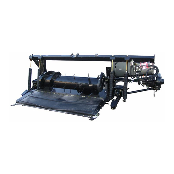
Summary of Contents for MacDon CA20
- Page 1 CA20, CA25, and FM100 Combine Adapters and Float Modules CE Chain Removal Instructions 214923 Revision A Original Instruction The harvesting specialists.
- Page 2 CA25 Combine Adapter FM100 Float Module Published February 2019...
- Page 3 Introduction Safety chains have been added to driveline halves and guards sold by MacDon Parts. These parts can be used to replace damaged driveline halves and guards on all MacDon CA20 and CA25 Combine Adapters and FM100 Float Modules. If servicing a driveline not originally equipped with safety chains, the chain on the replacement part needs to be removed first to prevent damage to the guard caused by only one half of the guard rotating during operation.
-
Page 5: Table Of Contents
2.1.2 Removing Driveline – CA20 and CA25 ....................7 2.2 Removing Driveline Guard........................8 2.3 Installing Driveline Guard .........................9 2.4 Installing Driveline ..........................11 2.4.1 Installing Driveline – FM100......................11 2.4.2 Installing Driveline – CA20 and CA25 ....................13 214923 Revision A... -
Page 7: Chapter 1: Safety
Chapter 1: Safety 1.1 Signal Words Three signal words, DANGER, WARNING, and CAUTION, are used to alert you to hazardous situations. Two signal words, IMPORTANT and NOTE, identify non-safety related information. Signal words are selected using the following guidelines: DANGER Indicates an imminently hazardous situation that, if not avoided, will result in death or serious injury. -
Page 8: General Safety
SAFETY 1.2 General Safety CAUTION The following general farm safety precautions should be part of your operating procedure for all types of machinery. Protect yourself. • When assembling, operating, and servicing machinery, wear all protective clothing and personal safety devices that could be necessary for job at hand. - Page 9 SAFETY • Wear close-fitting clothing and cover long hair. NEVER wear dangling items such as scarves or bracelets. • Keep all shields in place. NEVER alter or remove safety equipment. Make sure driveline guards can rotate independently of shaft and can telescope freely. •...
-
Page 11: Chapter 2: Installation Instructions
Chapter 2: Installation Instructions Refer to the following flowchart to determine if your model requires chain removal. Figure 2.1: Driveline Flowchart 1028263 214923 Revision A... -
Page 12: Removing Driveline
• 2.1.1 Removing Driveline – FM100, page 6 • 2.1.2 Removing Driveline – CA20 and CA25, page 7 2.1.1 Removing Driveline – FM100 WARNING To avoid injury or death from unexpected start-up of machine, always stop engine and remove key from ignition before leaving operator’s seat for any reason. -
Page 13: Removing Driveline - Ca20 And Ca25
INSTALLATION INSTRUCTIONS 2.1.2 Removing Driveline – CA20 and CA25 WARNING To avoid injury or death from unexpected start-up of machine, always stop engine and remove key from ignition before leaving operator’s seat for any reason. 1. Remove the two nuts (A) securing the shield (B) to the gearbox. -
Page 14: Removing Driveline Guard
INSTALLATION INSTRUCTIONS 2.2 Removing Driveline Guard 1. Slide the two halves of the driveline shaft apart. 2. On the guard being replaced, use a slotted screwdriver to release grease fitting/lock (A). Figure 2.6: Driveline Guard 3. Rotate the driveline guard locking ring (A) counterclockwise using a screwdriver until the lugs (B) line up with the slots in the guard. -
Page 15: Installing Driveline Guard
INSTALLATION INSTRUCTIONS 2.3 Installing Driveline Guard 1. Slide the guard onto the replacement driveline, and line up the slotted lug on the locking ring (A) with the arrow (B) on the guard. Figure 2.8: Driveline Guard 2. Push the guard onto the ring until the locking ring is visible in the slots (A). - Page 16 INSTALLATION INSTRUCTIONS 4. Push the grease fitting (A) back into the guard. 5. Grease the driveline. Figure 2.11: Driveline Guard 6. Assemble the driveline. IMPORTANT: The splines are keyed to align the universals. Align weld (A) with the missing spline (B) when assembling. Failure to align the halves of the shaft can cause excessive vibration and feed auger/gearbox failures.
-
Page 17: Installing Driveline
• 2.4.1 Installing Driveline – FM100, page 11 • 2.4.2 Installing Driveline – CA20 and CA25, page 13 2.4.1 Installing Driveline – FM100 WARNING To avoid injury or death from unexpected start-up of machine, always stop engine and remove key from ignition before leaving operator’s seat for any reason. - Page 18 INSTALLATION INSTRUCTIONS 3. Slide shield (A) over driveline (B). 4. Position the driveline quick disconnect onto the float module gearbox shaft, pull back the collar, and slide it onto the shaft until it locks in place. Release the collar. 5. Position shield (A) on the gearbox and secure with bolts (C). 6.
-
Page 19: Installing Driveline - Ca20 And Ca25
INSTALLATION INSTRUCTIONS 2.4.2 Installing Driveline – CA20 and CA25 DANGER To avoid bodily injury or death from unexpected start-up of machine, always stop engine and remove key from ignition before leaving operator’s seat for any reason. IMPORTANT: If the combine output shaft splines match the adapter input... - Page 22 MacDon Industries Ltd. MacDon Brasil Agribusiness Ltda. 680 Moray Street Rua Grã Nicco, 113, sala 404, B. 04 Winnipeg, Manitoba Mossunguê, Curitiba, Paraná Canada R3J 3S3 CEP 81200-200 Brasil t. (204) 885-5590 f. (204) 832-7749 t. +55 (41) 2101-1713 f. +55 (41) 2101-1699 MacDon, Inc.


Need help?
Do you have a question about the CA20 and is the answer not in the manual?
Questions and answers