
Related Manuals for Diamond Products CC8574DD


Summary of Contents for Diamond Products CC8574DD
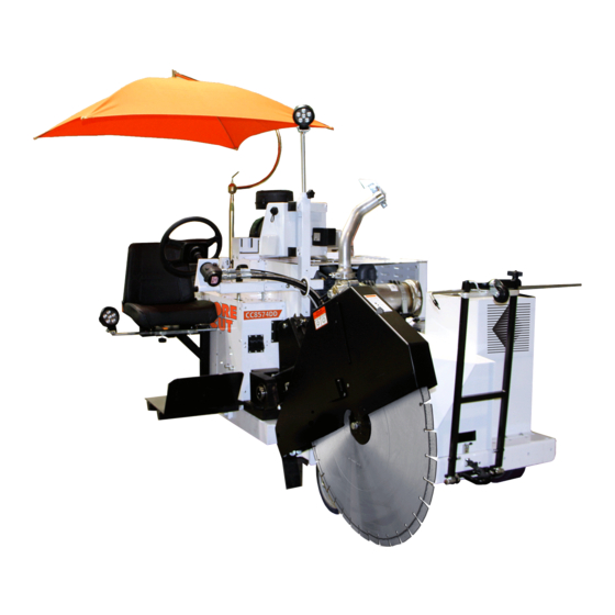
- Page 1 CORE CUT OPERATOR’S MANUAL CC8574DD RIDER SAW JULY 2020 Rev.: 20-01 Part #: 1808501...
-
Page 3: Table Of Contents
TABLE OF CONTENTS Introduction ............................. 7 CC8574DD Controls ..........................8 C8574DD Dimensions & Orientation Definition ..................12 CC8574DD Specifications ........................13 CC8574DD Specifications ........................14 Service Access Points .......................... 15 Front Hood ............................15 Top Access Panels ..........................15 Operator Side Access Panels ......................16 Service Side Panels .......................... - Page 4 TABLE OF CONTENTS Wheel Drive Control Lever ........................ 31 Control Grip Pushbuttons ....................... 32 Maneuvering the Machine Forward / Reverse with the Engine Running ........32 Moving the Machine with the Engine Off ..................32 Deactivating the Mechanical Brake ....................32 Activating the Mechanical Brake ....................
- Page 5 TABLE OF CONTENTS General Cleaning ..........................47 Cleaning Techniques ........................47 Radiator ............................47 Control Panel ..........................47 Engine ............................48 Part Lubrication ..........................48 Post Cleaning ............................ 48 Service Schedule ..........................49 Daily Service ............................50 Check Engine Oil Level ........................50 Check Fuel Level ..........................
- Page 6 Storing ............................... 69 Disposal ............................70 Appendix A ............................71 Troubleshooting ..........................71 Appendix B ............................72 CC8574DD RPM Chart ........................72 Appendix C ............................73 Additional Resources ........................73 Appendix D ............................74 Model and Serial Numbers ........................ 74...
-
Page 7: Introduction
Welcome to the Diamond Products family and thank you for choosing Diamond Products equipment. At Diamond Products we are driven to ensure you are completely satisfied with your product and continually strive to improve our product line so that we can offer you the best possible equipment in the industry. -
Page 8: Cc8574Dd Controls
INTRODUCTION CC8574DD Controls 1. Display Panel – Monitors and displays various engine and machine parameters. 2. Ignition Switch – Starts the engine and provides power to certain components. 3. Emergency Stop Button – Stops the engine. 4. Engine Throttle Switch – Increases and decreases engine/blade speed (RPM). - Page 9 INTRODUCTION 12. Blade Speed Control Lever – Adjusts blade pump outlet flow to operate the blade in a down cut or up cut direction. 13. Down Cut Stop Bolt – Set for a given blade size to quickly return to a desired speed. 14.
- Page 10 INTRODUCTION 19. Top Light – Provides area lighting. 20. Bottom Light – Provides area lighting. 21. Water Inlet Hose Connection – Attachment point for water supply 22. Steering Wheel – Provides directional control for vehicle movement.
- Page 11 INTRODUCTION 23. Water Control On/Off Control Valve – Turns water flow to the saw blade on and off and controls water flow rate. 24. Blade Raising Speed Valve – Controls the raising speed of the cutting arm assembly. 25. Blade Lowering Speed Valve – Controls the lowering speed of the cutting arm assembly.
-
Page 12: C8574Dd Dimensions & Orientation Definition
INTRODUCTION C8574DD Dimensions & Orientation Definition CC8745 Rider Saw Dimensions Inches Millimeters Saw Height - Max. 2286 Saw Height - Min. 1626 Saw Length - Max. 3226 Saw Length - Min. 2438 Frame Length 2261 Wheel Base Length 1778 Saw Width 1676 Frame Width 1194... -
Page 13: Cc8574Dd Specifications
INTRODUCTION CC8574DD Specifications... -
Page 14: Cc8574Dd Specifications
INTRODUCTION CC8574DD Specifications... -
Page 15: Service Access Points
INTRODUCTION Service Access Points Doors and panels are designed to provide easy access to internal parts and systems for maintenance purposes. These access points are located in the font, on the top, and on either side of the machine. Front Hood The front hood is located at the front of the saw and provides access to the hydraulic pump assembly. -
Page 16: Operator Side Access Panels
INTRODUCTION Operator Side Access Panels On the operator’s side of the machine there are two service access panel provided: 1. Fuel Component Access Door – Allows access to the following components: Fuel pump • Fuel pre-filter • Cutting arm raise/lower valve assembly •... -
Page 17: Service Side Panels
INTRODUCTION Service Side Panels There are two access panel located on the service or left side of the machine: 1. Service Side Engine Cover – Allows access to the maintenance side of the engine as well as the battery and wheel drive charge filter. 2. -
Page 18: Safety
California to cause cancer. For more information go Refer to the Diamond Products Parts List for additional information and part diagrams. Refer to the engine manual and manufacturer as the WWW.P65WARNINGS.CA.GOV... -
Page 19: Respiratory Hazards
SAFETY PRECAUTIONS under the frame base to properly support Respiratory Hazards the equipment. Repair the equipment immediately when a • WARNING problem arises. Concrete cutting produces dust and fumes Replace equipment decals if unreadable. • known to cause illness, death, cancer, respiratory disease, birth defects, and/or Dispose of all hazardous waste materials •... -
Page 20: Battery And Electrical Safety
SAFETY PRECAUTIONS Operate the equipment with anyone near Immediately rinse your clothing, skin, or • • the work area or within the direct line of the eyes with water if exposed to battery acid. blade. Seek medical attention immediately! Operate the equipment until all Disconnect the battery prior to servicing all •... -
Page 21: Blade Guard Safety
SAFETY PRECAUTIONS DO NOT use a blade for cutting that • Fuel Safety requires a lower speed than the blade shaft Always use caution when refueling. • speed. Store all fuel in appropriate safety • Always tighten the blade shaft bolt/screw as •... -
Page 22: Cutting Safety
SAFETY PRECAUTIONS components. If a particular component is Always operate the equipment in • under pressure when connection points are well-ventilated areas. loosened, oil may spray out forcefully. Concentrated engine exhaust can cause loss of consciousness and/or Always place a piece of •... -
Page 23: Lifting Safety
SAFETY PRECAUTIONS Use extreme caution when guiding the Lifting Safety • equipment up and down Move yourself and all others away • ramps. Slowly drive the from the lifting area when hoisting equipment forward down the the saw to prevent being crushed. ramp. -
Page 24: Display Panel Controller
CONTROL PANEL Display Panel Controller The display panel is a rugged Controller Area Network or CAN. This is a means of linking all of the electronic systems within the saw together allowing them to communicate with each other. This section explains the functions of the unit, describes the display screens and gives details about the configuration. -
Page 25: Soft Key Commands
CONTROL PANEL Soft Key Commands Columns of vertical commands may be located to the left and/or right of the display. They will change according to the options available for the screen being displayed. There are four basic icons associated with the soft key commands. These icons allow for the navigation through the sub-menus, selection of commands, or deselection of commands. -
Page 26: Home Screen
CONTROL PANEL Home Screen When the saw is operating, all essential parameters are monitored from the “Home” screen through a series of gauges and displays. At the center of the screen is a large digital gauge showing the blade speed (RPM), fuel level, and accumulated engine hours. Below that at the bottom of the screen is a digital bar gauge showing engine speed (RPM). -
Page 27: Menu Key Operations
Utilities This menu is used for recalibration of the depth stop sensor or to calibrate a new sensor. If access to this menu is required, contact Diamond Products Technical Department at (800) 321-5336. Engine Diagnostics This menu will open a screen of stored historic fault codes. These codes can be toggled through using the Up and Down arrow keys to the right of the screen. -
Page 28: User Settings
CONTROL PANEL User Settings This menu will display a screen allowing the operator to change some parametric settings. The yellow Up and Down arrows on the left allow you to move the cursor through the options. When the cursor highlights an option that can be changed, gray Up and Down arrows will appear on the right side of the display. -
Page 29: Enter Key Operations
CONTROL PANEL Enter Key Operations This feature is used when uploading new programs to the controller. Display Panel Operation Turning the ignition key switch to ON will open up the “Select Blade Size” screen with all active faults at the bottom of the screen. The active faults can be toggled through using the two lower function keys (Left &... -
Page 30: Status Displays
CONTROL PANEL The speed reducing gearbox has a temperature switch that will display an active fault message when the gearbox temperature reaches 180°F (82°C). The message can be turned off by using the upper right hand key on the controller. The high temperature fault will remain active until the condition clears. -
Page 31: Operating
OPERATING Operating Deactivating the Emergency Stop Prior to deactivating the emergency stop, ensure that General Operating Precautions the machine is back into a safe operating condition. Prior to operating the machine, read the • Then turn the emergency stop button clockwise until it operator’s manual thoroughly and ensure springs back into position. -
Page 32: Control Grip Pushbuttons
OPERATING 4. Turn the ignition switch to the START Control Grip Pushbuttons position until the engine starts, then release The control grip pushbuttons only work with the the switch. The key will return to the ON ignition key at ON or with the engine running. position. - Page 33 OPERATING 4. Locate the “Brake Release kit” bolted to the 9. At the rear drive wheel, remove the rubber lower left rear panel of the saw near the plug from the brake protector at the center battery. of the wheel motor. 10.
-
Page 34: Activating The Mechanical Brake
OPERATING WARNING With the manual brake deactivated, DO NOT attempt to manually push the machine while it is on a grade or slope. The machine could roll uncontrolled causing personal injury or property damage Activating the Mechanical Brake 1. Place wheel chocks under the rear wheel in both directions. -
Page 35: Fuel System
OPERATING Fuel System Blade Guard WARNING WARNING DO NOT operate the saw with the blade guard Always use caution when refueling. • raised or removed. DO NOT operate the saw with a fuel • DO NOT remove the blade guard with the leak. -
Page 36: Installing The Blade Guard
OPERATING 3. Remove the lock pin from the tapered Installing the Blade Guard frame mount. Always install the blade guard with the blade off 4. Use the handle on the blade guard to rock the saw. the guard back and forth while lifting the 1. -
Page 37: Wrench
OPERATING 3. Slide the cutting motor shaft into the Wrench gearbox until seated and bolt the cutting Use the wrench provided when installing or motor to the gearbox using four 1/2"-13 hex removing a blade. Apply force to the opposite head bolts, lock washers, and flat washers. -
Page 38: Installing The Blade
OPERATING 4. Disconnect the harness ends for the pillow NOTE: For blades 42” and larger, ensure the block sensor, temperature switch, oil pump, speed reducing gearbox is installed on the and fan from the main wiring harness in cutting head. accordance with the electrical schematic located in the CC8574 Parts List Manual. -
Page 39: Removing The Blade
OPERATING 6. Place the blade against the inner flange. Removing the Blade For large blades, carefully roll the blade up to the inner flange. Adjust the height of CAUTION the saw to align the flange and blade • DO NOT remove a blade with the arbor. -
Page 40: Engine
OPERATING 5. Carefully remove the outer flange and Check fluids and fill to appropriate levels. • blade. Place the blade in an appropriate Turn off controls and switches. • storage location. Remove tools from area. • The engine will not start unless the following NOTE: If the outer flange is difficult to remove, tasks are completed: tighten a setscrew into two of the holes on the... -
Page 41: Stopping The Engine
OPERATING Stopping the Engine Water Supply (Non Water Pump) The water supply directs cooling water to the CAUTION blade and minimizes dust when cutting. The DO NOT leave the saw unattended until the water supply hose connection is located under engine is off and the blade has stopped the operator’s seat to the rear of the saw. -
Page 42: Water Supply (Optional Water Pump)
OPERATING 4. If a water pump is installed, close the water pump isolation valve to prevent back pressurizing the pump. 5. Start the flow of water from the source to the saw. 6. To start the flow of water to the blade guard, open the water control valve by rotating the valve handle toward the rear of the saw. -
Page 43: High Pressure Operation With The Water Pump Installed
OPERATING 4. Ensure that the water pump isolation valve 4. Divide an 8–10 ft. piece of string in half. located underneath and to the front of the 5. Place the looped end of string into a gullet operator’s seat is open. on the backside of the blade. -
Page 44: Tasks Prior To Cutting
Refer to the Diamond Products’ Guide for • 11. Continue the step-cut process to reach the Professional Concrete Cutters for maximum depth. -
Page 45: Continuing A Partial-Cut
OPERATING 8. If you are cutting more than 2” deep, you There are two spotlights available to provide can finish the job in less time and effort by work area lighting. The top spotlight is located step cutting in 2” increments. Cut a 2” on the steering upright assembly. -
Page 46: Strobe Light
OPERATING Strobe Light Umbrella An amber strobe warning light is provided on Opening the Umbrella the saw for visibility safety. The strobe light is 1. Insert the swivel ball locking handle into the located on the steering upright assembly next umbrella support shaft. -
Page 47: Maintenance
General Cleaning Refer to the CC8574DD Parts List for The saw must be cleaned after each use and additional information and part diagrams when prior to conducting any maintenance. Ensure performing maintenance tasks. -
Page 48: Engine
MAINTENANCE Engine Post Cleaning Use a mild detergent and water to clean the Lubricate the machine as required. • engine. Do not to spray water forcefully on the Dry all electrical components using • engine to prevent damage to components. compressed air. -
Page 49: Service Schedule
MAINTENANCE Service Schedule The service schedule is based primarily on the standard operating time of the machine. The frequency of the maintenance tasks can be increased based on the working environments of the machine. -
Page 50: Daily Service
MAINTENANCE 5. Using a funnel, add oil, in accordance with Daily Service the “Specifications” table located in the Check Engine Oil Level Introduction section of this manual, until the level is correct. Prior to checking the engine oil level, ensure 6. -
Page 51: Check Hydraulic Fluid Level
8. Close the water valve. 9. Shut off water supply and disconnect from The coolant system on the CC8574DD is a the water manifold. pressurized system. Care must be taken when 10. Pull the detent pin on the blade guard servicing the system. -
Page 52: Check Air Cleaner Restriction Indicator
MAINTENANCE Check Air Cleaner Restriction Indicator 1. Check the restriction indicator located on the outlet to the air cleaner. Restriction Indicator 2. If the indicator is red, clean the air cleaner outer primary filter in accordance with the Rubber Dust Ejector Boot “Clean the Outer Primary Air Filter”... -
Page 53: Drain The Fuel Pre-Filter Water Separator
MAINTENANCE 1. Ensure the engine is turned off and the saw frame is level. 2. Disconnect the water supply hose to the blade guard at the water valve. 3. Disconnect the wire harness to the seat safety switch. Outer Primary Filter 5. -
Page 54: 100 Hour Service
MAINTENANCE 10. Close and latch the fuel door. Replacing the Oil in the Planetary Speed 11. Rotate the seat back into position, reinstall Reduction Gearbox the three hex head bolts and tighten to NOTE: If it is known that the planetary speed secure. -
Page 55: Adding Oil To The Planetary Speed Reducing Gearbox
MAINTENANCE Adding Oil to the Planetary Speed Reducing Gearbox 1. Ensure the engine is OFF. 2. Disconnect the air purge tank hose at the 1/4" JIC fitting attached to the 1/4" elbow on the discharge side of the cooler. Filler Breather Cap Air Purge Tank Air Purge Tank Hose Oil Drain Hose and Valve... -
Page 56: 500 Hour Service
MAINTENANCE 11. Remove the access cover plate located on associated with it and will provide a visual the engine cover panel to access the oil fill indication on the display when it requires cap. replacing. There is a second filter, the hydraulic blade pump charge filter, located on the front hydraulic blade pump. - Page 57 MAINTENANCE 12. Replace the ten inch access cover on the side of the tank and secure the bolt using a 15/16” wrench. 13. Insert the filter cartridge back into the filter bowl assembly and ensure that it is seated. 14. Place the bypass valve onto the filter. 15.
-
Page 58: Gravity Drain
MAINTENANCE 21. When all oil has been drained, wipe the sealing surface of the oil filter mounting bracket and the area around the pump with a clean lint free cloth. 22. Dispose of the oil and filter in accordance with all city, state, and federal regulations. 23. - Page 59 MAINTENANCE 5. Using a 7/8” wrench, remove the drain plug 12. Place a suitable collecting receptacle under from the bottom of the reservoir tank and the hydraulic blade pump charge filter. allow the oil to drain. Hydraulic Blade Pump Charge Filter 13.
-
Page 60: Replace The Secondary Fuel Filter
MAINTENANCE 20. When all oil has been drained, wipe the Replace the Secondary Fuel Filter filter head area of all oil with a clean lint 1. Ensure the engine is turned off and the saw free cloth. frame is level. 21. -
Page 61: Replacing The Outer Primary And Inner Safety Air Filters
MAINTENANCE 12. Reconnect the sensor wire to the drainage cap/switch assembly. 13. Rotate the seat back into position and reinstall and tighten all bolts. 14. Re-connect the wire harness to the seat safety switch. 15. Reconnect the water supply hose to the blade guard onto the water valve. -
Page 62: 1000 Service Hours
MAINTENANCE 1000 Service Hours Replace the Fuel Pre-Filter Replace the fuel pre-filter periodically to prevent wear on the fuel pump due to dirt in the fuel. 1. Ensure the engine is turned off and the saw frame is level. 2. Disconnect the water supply hose to the blade guard at the water valve. -
Page 63: Year Service
Refer to the 6. Press a section of the widest end of the CC8574DD Part’s List Manual for additional inner bearing into the outer edge of the information and diagrams. grease closest to the thumb forcing grease up into the interior of the bearing. - Page 64 MAINTENANCE a) Using a 7/16” wrench, remove the two 1/4”-20 self-tapping screws from the front of the engine cover stiffener and set aside. b) Using a 10mm wrench, remove the seven M6 x16mm hex head cap screws and washers attaching the hose thru panel to the engine cover plate and set aside.
-
Page 65: Year Service
11. Using the socket wrench, allow the tension Refer to the CC8574DD Parts List Manual for roller to move clockwise and tension the v- additional information. ribbed belt. 12. Check the belt to ensure it is properly 1. -
Page 66: Engine
MAINTENANCE The saw contains a charged battery with one Engine positive cable lead and one negative cable lead. WARNING Let the engine cool down prior to Battery Type servicing the saw. 12 Volt, Group 24 DO NOT service the saw with the Servicing the Battery engine running (unless stated otherwise). -
Page 67: Electrical System
MAINTENANCE The second location is located just inside the Electrical System upper front control panel where the control cable connects to the wheel drive control lever. WARNING There are two jam nuts at this end of the cable Never weld on the machine with the ECU for adjustment as well. -
Page 68: Adjusting The Wheel Drive Control Lever Tension
MAINTENANCE The cable has a rod end located on the cable 2. Disconnect the water supply hose to the to adjust the cable length as necessary. The blade guard at the water valve. second location is located just outside the 3. -
Page 69: Adjusting The Wheel Drive Control Lever Spring Plungers
MAINTENANCE Spring Plunger Hex Nuts 2. Screw the spring plungers slightly out to let the speed control lever move easily into Grease Cap and out of the STOP/PARK position. Screw the spring plungers slightly in to let the speed control lever move forward and backward firmly in the forward/reverse slot. -
Page 70: Disposal
MAINTENANCE Lower the blade arm completely to remove • Disposal strain on the lifting mechanism. Dispose of the saw when it’s no longer Clean and wipe down the saw to remove • repairable, and/or contains safety hazards not dust, debris, and slurry from saw worth repairing or maintaining. -
Page 71: Troubleshooting
REFERENCE Appendix A Troubleshooting Troubleshooting the CC8574DD Symptom Problem Solution Out of Fuel? Fill fuel tank. Fuel lines clogged? Unclog or replace fuel lines. Air in fuel lines? Bleed fuel lines. Worn out battery? Charge or replace battery. 1. Engine will not start. -
Page 72: Cc8574Dd Rpm Chart
REFERENCE Appendix B CC8574DD RPM Chart... -
Page 73: Additional Resources
Appendix C Additional Resources 1. Deutz (www.deutzamericas.com) Operator’s Manual Deutz Engine, TD 2.9 L4 • 2. Diamond Products (www.diamondproducts.com) CC8574DD Parts List • A Guide for Professional Concrete Cutters • Training Manual – Introduction to Diamond Blades, Bits, and Equipment •... -
Page 74: Model And Serial Numbers
REFERENCE Appendix D Model and Serial Numbers Record the saw’s serial number below for future reference and customer service purposes. Serial Number Record the engine’s model and serial numbers below for future reference and customer service purposes. Model Number Serial Number... - Page 76 (1) year from the date of shipment to Customer. The responsibility of Diamond Products under this Warranty is limited to replacement or repair of defective parts at Diamond Products’ Elyria, Ohio...
Need help?
Do you have a question about the CC8574DD and is the answer not in the manual?
Questions and answers