Table of Contents
Advertisement
Advertisement
Table of Contents

Subscribe to Our Youtube Channel
Related Manuals for Evinox ModuSat FS Series


Summary of Contents for Evinox ModuSat FS Series
- Page 1 ModuSat FS Unit Installation Manual...
-
Page 2: Table Of Contents
CONTENTS GENERAL INFORMATION ......................9 Warnings........................... 9 Symbols ..........................9 Safety Instructions ......................9 TECHNICAL FEATURES........................11 Hydraulic Schematics & dimensions ................... 11 Dimensions ........................14 Technical data ........................16 INSTALLATION ..........................21 Recommended handling procedure ................... 21 ModuSat FS positioning ....................22 Checks before connecting the ModuSat FS ................. - Page 3 Apartment Circuit Balancing ..................... 45 Use of the commissioning switch ..................46 Adjustment of TMV ......................47 Pump Start-up - Wilo PWM Pump ..................48 Warranty.......................... 49...
- Page 4 Label for ModuSat FS 80 Main features (BS EN12897 2006) Manufacturer: Evinox Energy Ltd Unit 37, Barwell Business Park Leatherhead Road, Chessington, Surrey KT9 2NY Tel : + 44 (0)1372 722277 www.evinoxenergy.co.uk Model: ModuSat FS 80 Serial number: ______________ Year of manufacture:...
- Page 5 Label for ModuSat FS 150 Main features (BS EN12897 2006) Manufacturer: Evinox Energy Ltd Unit 37, Barwell Business Park Leatherhead Road, Chessington, Surrey KT9 2NY Tel : + 44 (0)1372 722277 www.evinoxenergy.co.uk Model: ModuSat FS 150 Serial number: ______________ Year of manufacture:...
- Page 6 Label for ModuSat FS 200 Main features (BS EN12897 2006) Manufacturer: Evinox Energy Ltd Unit 37, Barwell Business Park Leatherhead Road, Chessington, Surrey KT9 2NY Tel : + 44 (0)1372 722277 www.evinoxenergy.co.uk Model: ModuSat FS 200 Serial number: ______________ Year of manufacture:...
- Page 7 Label for ModuSat FS 300 Main features (BS EN12897 2006) Manufacturer: Evinox Energy Ltd Unit 37, Barwell Business Park Leatherhead Road, Chessington, Surrey KT9 2NY Tel : + 44 (0)1372 722277 www.evinoxenergy.co.uk Model: ModuSat FS 300 Serial number: ______________ Year of manufacture:...
- Page 8 Label for ModuSat FS 400 Main features (BS EN12897 2006) Manufacturer: Evinox Energy Ltd Unit 37, Barwell Business Park Leatherhead Road, Chessington, Surrey KT9 2NY Tel : + 44 (0)1372 722277 www.evinoxenergy.co.uk Model: ModuSat FS 400 Serial number: ______________ Year of manufacture:...
-
Page 9: General Information
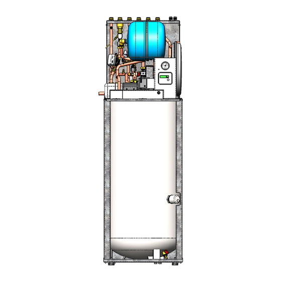
Evinox representative. Any modifications or adjustments carried out without EVINOX official authorisation will invalidate the warranty and absolves Evinox from any liability. Evinox has the right to make any changes or modifications to the products without prior notice. Symbols... - Page 10 ModuSat FS 200 ModuSat FS 150 ModuSat FS 80 Please note: Images shown include the optional factory fitted immersion heater. ModuSat FS 400 ModuSat Tank Without immersion heater fitted FS 300...
-
Page 11: Technical Features
2 TECHNICAL FEATURES Hydraulic Schematics & dimensions ModuSat FS 80 & 150 Schematic Components Heat meter Controls & Other Items Primary / DH flow Non-return valve Wireless RS 485 (Optional) Primary / DH return DHW Secondary Side Circuit Electronic control board Domestic cold water Inlet External lime scale reducer Room control unit... - Page 12 ModuSat FS 200 Schematic Components control valve (PICV) with Controls & Other Items Primary / DH flow actuator Wireless RS 485 (Optional) Primary / DH return Heat meter Electronic control board Domestic cold water Inlet Non-return valve Room control unit Domestic hot water outlet DHW Secondary Side Circuit IV (Strainer + flushing...
- Page 13 ModuSat FS 300 & 400 Schematic Components Pressure independent Drain point Primary / DH flow control valve (PICV) with Controls & Other Items Primary / DH return actuator Wireless RS 485 (Optional) Domestic cold water Inlet Heat meter Electronic control board Domestic hot water outlet Non-return valve Room control unit...
-
Page 14: Dimensions
Dimensions ModuSat FS 80 & 150... - Page 15 ModuSat FS 200...
- Page 16 ModuSat FS 300 & 400...
-
Page 17: Technical Data
Technical data ModuSat FS 80 & 150 Electrical ModuSat FS 80 ModuSat FS 150 Electric supply 220/240 Volt (AC) Frequency 50 Hz Current absorption 0.6A (Without immersion Heater) Optional immersion heater 220/240 Volt (AC) Hydraulic connections ModuSat FS 80 ModuSat FS 150 Primary circuit supply ¾”... - Page 18 ModuSat FS 200 Electrical ModuSat FS 200 Electric supply 220/240 Volt (AC) Frequency 50 Hz Current absorption 0.6A (Without immersion Heater) Optional immersion heater 220/240 Volt (AC) Hydraulic connections ModuSat FS 200 Primary circuit supply ¾” ext. thread Primary circuit return ¾”...
- Page 19 ModuSat FS 300 & 400 Electrical ModuSat 300 ModuSat 400 Electric supply 220/240 Volt (AC) Frequency 50 Hz Current absorption 1.5A (Without immersion Heater) Optional immersion heater 9000 W – 415 Volt (AC) 3 Phase Hydraulic connections ModuSat FS 300 ModuSat FS 400 Primary circuit supply 1”...
- Page 20 Technical performance table ModuSat® ModuSat® ModuSat® ModuSat® ModuSat® FS 80 FS 150 FS 200 FS 300 FS 400 Water capacity Litres Primary flow rate at 80⁰C Nom / Max l / h 1000 1300 1600 1500 1900 Exchanger power Nom / Max Continuous DHW flow rate at 45⁰C l / m Pre-heat time from 15⁰C to 60⁰C...
-
Page 21: Installation
INSTALLATION The installation and commissioning of the units should be carried out only by competent and qualified personnel according to the current regulations and standards. Recommended handling procedure ModuSat 80, 150 & 200 - The unit should be moved into position still within its packaging and on its pallet to prevent any damage whilst being positioned. -
Page 22: Modusat Fs Positioning
In case of damage please contact Evinox immediately. Packaging materials must be properly disposed of in line with current environmental guidelines. -
Page 23: Checks Before Connecting The Modusat Fs
All electrical wiring should be installed / checked by qualified personnel in line with current regulations. EVINOX are not liable for damage caused by incorrect electric connections or faulty wiring. The ModuSat should be provided with additional fused protection. This will be via... -
Page 24: Use Of Pre-Installation Rig
INSTALLATION RIG STEP1: Temporarily fix the Pre- Installation Rig against the wall in the required position. STEP2: Fit the Evinox Flushing Bypass & Valve Kit to the rig and then make final connections to the pipework running to the HIU. -
Page 25: Installation Of Safety Discharges
Installation of Safety Discharges The opening temperature of the P & T valve is 90°C. The position of the tundish should be visible to the occupants and must be positioned away from any electrical devices. Refer to the drawing below for typical tundish position, discharge pipe and connection details. - Page 26 Worked example The example below is for a G 1/2 temperature relief valve with a discharge pipe (D2) having 4 no. elbows and length of 7m from the tundish to the point of discharge. From Table 1 • Maximum resistance allowed for a straight length of 22mm copper discharge pipe (D2) from a G 1/2 temperature relief valve is 9.0m Subtract the resistance for 4 no.
- Page 27 Optional Way to Discharge P & T Valve...
-
Page 28: Pressure Independent Control Valves (Picv)
Pressure Independent Control Valves (PICV) FS 80, 150 & 200 PICV FS 300 & 400 PICV Valve Model DN20 2.5mm No Presetting DN20 5.5mm High Maximum flow rate 1450 l/h +/- 10% 1800 l/h +/- 10% Start up ∆P 25 kPa 40 kPa Max differential ∆P 800 kPa... -
Page 29: Primary And Secondary Circuit
The valve should be set to 125% above the design flow rate. The project specific set-point (if required) can be confirmed by Evinox Energy. Tighten Actuator Connections Ensure that the actuators are tightened to ensure the operation of the unit. -
Page 30: Precautions
• Frequent top ups due to leaks, repair and maintenance. • Use of water with characteristics that are not in line with the recommendations within this manual or in line with BSRIA / Evinox requirements. Precautions The correct operation of the unit, as well as the entire system, depends on good water quality. -
Page 31: Bionibal
IT IS ADVISABLE to ADD a suitable approved corrosion inhibitor before the system is put in operation. Bionibal dosage and use (If used & when required if Evinox boiler plant is installed) NEW INSTALLATIONS: Fill the circuit with water and check for leaks... -
Page 32: Initial Opening / Filling Of The Unit
flush / drain as required. In some cases, the system may need washing by a suitable product: SUGGESTED DOSE • 2 litres for every 100 litres of primary network • 1 litre for every 100 litres of the radiator circuit capacity •... -
Page 33: Flushing Bypass
Flushing Bypass Unit bypassed Flushing bypass Isolation valves are closed (Handles in horizontal position) and bypass is open. Turn screw in horizontal position for flushing of primary system. Unit in normal operation (Open to primary system) Isolation valves are opened (Handles in vertical position) and bypass valve is closed with screw in vertical position. -
Page 34: Tank Draining
Tank draining The cylinder drain is located on the bottom part of the integrated tank. Procedure: • Switch off and isolate all mains electricity supply to the unit. • Close hot isolation valve • Slowly close the mains water supply valve. •... -
Page 36: Electric Connections
The unit is not protected from lightning. Auxiliary connections Don’t connect the Evinox room controller unit to a mains supply as this will cause permanent damage. • Use the relevant terminal connections and a suitable 4 wire shielded cable (4 x 0.35mm²) for this connection and follow the procedure on the following page... -
Page 37: Modusat Wiring Connections
Modusat Wiring Connections The modusat wiring board is located within the modusat itself under a removable metal cover. To access the wiring board the full front case cover (Or front top cover if a 200, 300 or 400 litre unit) should be removed. The connections board will be to your left as shown, to take off the cover the retaining screw should be removed and the cover lifted off. - Page 38 Guides for the various connection applications and requirements are detailed in the wiring principle drawings shown on pages 31-32. Evinox strongly recommend in accordance with best practice that all wiring connections to the board, especially the BUS and room controller are terminated using ‘bootlace ferrule’...
-
Page 39: Modusat Connection Board (Visible Once The Cover Is Removed)
ModuSat Connection Board (Visible once the cover is removed) Please Note: When connecting external valves or pumps to the control board of the ModuSat, it must be ensured that each connection does not exceed 1amp @ 220/240 volts (AC) -
Page 40: Room Controller Connections
Room controller connections The Room controller is a white ABS box with a graphic display. It should be installed in the main living area of the dwelling. It must be connected to the control wiring board within the ModuSat (please refer to the electrical diagram) using a 4x0.35 mm2 screened cable. - Page 41 Once the tab has been Connection terminal with releasees the cover can be room controller hinged up to access connection 4 x 0.35 sqmm + sheild...
-
Page 42: Typical Modusat Electric Wiring Diagram (Single Room Controller)
Typical ModuSat Electric Wiring Diagram (Single Room Controller) Note 3: Pumps & valves must have localized power supply. Switched neutral connection to be fitted with 1 amp in-line fuse on neutral cable. -
Page 43: Typical Modusat Electric Wiring Diagram With 2 Zone Control (2 Room Controllers)
Typical ModuSat Electric Wiring Diagram with 2 Zone Control (2 Room Controllers) Note 3: Pumps & valves must have localized power supply. Switched neutral connection to be fitted with 1 amp in-line fuse on neutral cable. -
Page 44: Commissioning
This prevents the components being exposed to excessive hydraulic shock. If there is a problem with any of the above listed checks, contact Evinox immediately and DO NOT OPERATE THE UNIT until rectified. -
Page 45: Apartment Circuit Balancing
The unit will then require full commissioning by an Evinox engineer. During the commissioning procedure the unit will be fully set up to the system design parameters. All commissioning must be booked well in advance and will be carried out to a pre-agreed programme. -
Page 46: Use Of The Commissioning Switch
45 mins. Please note: The rocker switch above the commissioning push button is the Pump Manual Override. This should NOT be operated or used by persons other than Evinox Engineers as it is for emergency use only. -
Page 47: Adjustment Of Tmv
Adjustment of TMV The ModuSat unit is fitted with an internal blending valve on the DHW outlet from the integral storage tank. This enables the DHW storage temperature to be higher to improve DHW recovery and draw off rates but also ensure that the DHW to outlets does not exceed the design / safe temperatures as an additional fail safe protection. -
Page 48: Pump Start-Up - Wilo Pwm Pump
Pump Start-up - Wilo PWM Pump The Wilo Pulse-width modulation (PWM) pump features dry running protection to eliminate burn out and provides compliance with the 2015 pump efficiency regulations. Description of the pump The pump consists of a hydraulic system, a glandless pump motor with a permanent magnet rotor, and an electronic control module with an integrated frequency... -
Page 49: Warranty
Replacement parts are chargeable until passed as faulty by Evinox, when a credit will be provided. Any parts that have failed as a result of poor servicing or misuse will not be covered by our warranty. - Page 50 Installation of the Evinox unit should only be carried out by suitably qualified personnel (I.e. approved to install unvented systems in line with Water Supply (water fittings) Regulations 1999 and Building Regulations 1991 Part C (B.R Part C 1992) and also have relevant approval for associated plumbing and electrical works.
Need help?
Do you have a question about the ModuSat FS Series and is the answer not in the manual?
Questions and answers