Vex Robotics CLAWBOT Building Instructions
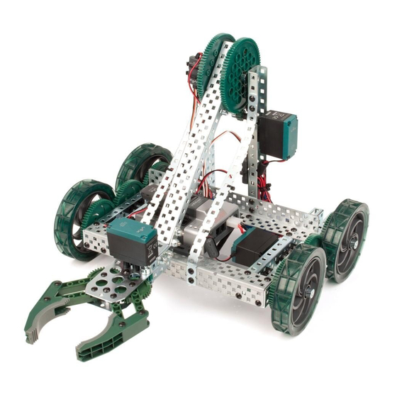
Clawbot with sensors
Hide thumbs
Also See for CLAWBOT:
- Build instructions (28 pages) ,
- Assembly manual (20 pages) ,
- Build instructions (28 pages)

Related Manuals for Vex Robotics CLAWBOT


Summary of Contents for Vex Robotics CLAWBOT
- Page 1 RO O R BOT T C C C CLAWBOT BUILDING INSTRUCTIONS CLAWBOT WITH SENSORS BUILDING INSTRUCTIONS USING THE VEX CORTEX Clawbot 1.0 • © 2013 Carnegie Mellon Robotics Academy / For use with VEX Robotics Systems ®...
- Page 2 RO O R BOT T C C C CLAWBOT BUILDING INSTRUCTIONS Collect the parts and tools from the list below to attach the sensors: Note that this robot can only Materials Quantity be built if you have a standard Shaft, 4” Long Clawbot already assembled Shaft, 5”...
- Page 3 RO O R BOT T C C C CLAWBOT BUILDING INSTRUCTIONS Attaching the Bumper Sensor 3/4” Place screws through the bump sensor and place thin spacers on the opposite side Clawbot 1.0 • © 2013 Carnegie Mellon Robotics Academy / For use with VEX Robotics Systems ®...
- Page 4 RO O R BOT T C C C CLAWBOT BUILDING INSTRUCTIONS Attaching the Bumper Sensor (continued) Attach the bump sensor as shown below Bottom View Front View Clawbot 1.0 • © 2013 Carnegie Mellon Robotics Academy / For use with VEX Robotics Systems ®...
- Page 5 RO O R BOT T C C C CLAWBOT BUILDING INSTRUCTIONS Attaching the Ambient Light Sensor 3/8” Claw is hidden for visibility purposes Front View Top View Clawbot 1.0 • © 2013 Carnegie Mellon Robotics Academy / For use with VEX Robotics Systems ®...
- Page 6 RO O R BOT T C C C CLAWBOT BUILDING INSTRUCTIONS Attaching the Potentiometer To attach the Potentiometer, C-Channel holding the arm Remove the arm motor along with the clutch post and shaft coupler Next, remove the left, bent bar and its screws and nuts Clawbot 1.0...
- Page 7 RO O R BOT T C C C CLAWBOT BUILDING INSTRUCTIONS Attaching the Potentiometer (continued) This is what the robot should look like after the bar is removed Remove the shaft collar below Clawbot 1.0 • © 2013 Carnegie Mellon Robotics Academy / For use with VEX Robotics Systems ®...
- Page 8 RO O R BOT T C C C CLAWBOT BUILDING INSTRUCTIONS Attaching the Potentiometer (continued) Carefully slide the C-Channel off the arm structure. Keep the bearing blocks intact. Take the metal bar and remove the bearing blocks and rivets. Clawbot 1.0 •...
- Page 9 RO O R BOT T C C C CLAWBOT BUILDING INSTRUCTIONS Attaching the Potentiometer (continued) Reattach the block on the opposite side of the metal bar block and 2 rivets. We will use it later for the limit switch. 3/4”...
- Page 10 RO O R BOT T C C C CLAWBOT BUILDING INSTRUCTIONS Attaching the Potentiometer (continued) Reattach the bent bar we removed earlier Re-attach the arm motor along with the clutch post and shaft coupler Clawbot 1.0 • © 2013 Carnegie Mellon Robotics Academy / For use with VEX Robotics Systems ®...
- Page 11 RO O R BOT T C C C CLAWBOT BUILDING INSTRUCTIONS Attaching the Potentiometer (continued) Make sure your structure looks like this before moving on Replace the uppermost shaft of the arm with a longer shaft. Clawbot 1.0 • © 2013 Carnegie Mellon Robotics Academy / For use with VEX Robotics Systems ®...
- Page 12 RO O R BOT T C C C CLAWBOT BUILDING INSTRUCTIONS Attaching the Potentiometer (continued) The shaft should be around 4” in length 4” Place a thick spacer on the shaft Clawbot 1.0 • © 2013 Carnegie Mellon Robotics Academy / For use with VEX Robotics Systems ®...
- Page 13 RO O R BOT T C C C CLAWBOT BUILDING INSTRUCTIONS Attaching the Potentiometer (continued) Slide the structure back in place. Both C-Channels should now open to the right. Building Tip - Potentiometer Range of Motion At this step, make sure the arm rotates within the potentiometer’s range of motion.
- Page 14 RO O R BOT T C C C CLAWBOT BUILDING INSTRUCTIONS Attaching the Potentiometer (continued) Screw the screws and nuts shown below back into place Finish by putting on the shaft collar we removed earlier Building Tip - Using Shaft Collars Clawbot 1.0...
- Page 15 RO O R BOT T C C C CLAWBOT BUILDING INSTRUCTIONS Attaching the Potentiometer (continued) Push the arm structure inwards and make sure everything is tight Make sure the arm moves freely Clawbot 1.0 • © 2013 Carnegie Mellon Robotics Academy / For use with VEX Robotics Systems ®...
- Page 16 RO O R BOT T C C C CLAWBOT BUILDING INSTRUCTIONS Attaching the Sonar Sensor 3/4” Much like the bumper sensor, start with 2 screws and a spacer Orthographic view Top-down view Clawbot 1.0 • © 2013 Carnegie Mellon Robotics Academy / For use with VEX Robotics Systems ®...
- Page 17 RO O R BOT T C C C CLAWBOT BUILDING INSTRUCTIONS Attaching the Sonar Sensor (continued) Attach the sonar to the front of the robot The side rail is hidden for visibility purposes Clawbot 1.0 • © 2013 Carnegie Mellon Robotics Academy / For use with VEX Robotics Systems ®...
- Page 18 RO O R BOT T C C C CLAWBOT BUILDING INSTRUCTIONS Attaching the Limit Switch 3/4” The limit switch is also attached using 2 screws and spacers Orthographic view Top-down view Clawbot 1.0 • © 2013 Carnegie Mellon Robotics Academy / For use with VEX Robotics Systems ®...
- Page 19 RO O R BOT T C C C CLAWBOT BUILDING INSTRUCTIONS Attaching the Limit Switch (continued) Place the sensor in between the bent bars on the front of the robot like such Front view from a bottom perspective Clawbot 1.0 •...
- Page 20 RO O R BOT T C C C CLAWBOT BUILDING INSTRUCTIONS Attaching the Limit Switch (continued) Recover the bearing Building Tip - Using Pop Rivets block you saved earlier from the potentiometer build. Place it underneath the claw as shown below.
- Page 21 RO O R BOT T C C C CLAWBOT BUILDING INSTRUCTIONS Line Tracking Sensor Construction 3/4” Next, attach the line tracking sensors Make sure the line trackers are centered on the robot Bottom View Clawbot 1.0 • © 2013 Carnegie Mellon Robotics Academy / For use with VEX Robotics Systems ®...
- Page 22 RO O R BOT T C C C CLAWBOT BUILDING INSTRUCTIONS Attaching the Gyroscope 3/4” Attach the gyroscope as close to the center as possible Below is the top view Clawbot 1.0 • © 2013 Carnegie Mellon Robotics Academy / For use with VEX Robotics Systems ®...
- Page 23 RO O R BOT T C C C CLAWBOT BUILDING INSTRUCTIONS This robot model features 2 options for motor encoder:. A.) Attaching the external VEX Quadrature Encoders to the shafts connecting the back wheels to the drive train. B.) Using the Integrated Motor Encoders.
- Page 24 RO O R BOT T C C C CLAWBOT BUILDING INSTRUCTIONS Attaching the Left Encoder Take an angle gusset and an encoder 3/8” Option A: This section covers how to assemble the external Quadrature Encoders. If you would like to use...
- Page 25 RO O R BOT T C C C CLAWBOT BUILDING INSTRUCTIONS Attaching the Left Encoder (continued) 3/4” At the end of the gusset, place a screw and a thin spacer as shown below Clawbot 1.0 • © 2013 Carnegie Mellon Robotics Academy / For use with VEX Robotics Systems ®...
- Page 26 RO O R BOT T C C C CLAWBOT BUILDING INSTRUCTIONS Attaching the Left Encoder (continued) Now do the same for the right encoder 3/8” Clawbot 1.0 • © 2013 Carnegie Mellon Robotics Academy / For use with VEX Robotics Systems...
- Page 27 RO O R BOT T C C C CLAWBOT BUILDING INSTRUCTIONS Attaching the Left Encoder (continued) 3/4” Just like the potentiometer, to build the encoders, we will need to lengthen the shaft Clawbot 1.0 • © 2013 Carnegie Mellon Robotics Academy / For use with VEX Robotics Systems ®...
- Page 28 RO O R BOT T C C C CLAWBOT BUILDING INSTRUCTIONS Attaching the Left Encoder (continued) 5” Clawbot 1.0 • © 2013 Carnegie Mellon Robotics Academy / For use with VEX Robotics Systems ®...
- Page 29 RO O R BOT T C C C CLAWBOT BUILDING INSTRUCTIONS Attaching the Left Encoder (continued) 5” Remove these shaft collars and replace them with 2 thick spacers on each side Clawbot 1.0 • © 2013 Carnegie Mellon Robotics Academy / For use with VEX Robotics Systems ®...
- Page 30 RO O R BOT T C C C CLAWBOT BUILDING INSTRUCTIONS Attaching the Left Encoder (continued) Slide the shaft through the encoder and then place the screws as shown below Clawbot 1.0 • © 2013 Carnegie Mellon Robotics Academy / For use with VEX Robotics Systems ®...
- Page 31 RO O R BOT T C C C CLAWBOT BUILDING INSTRUCTIONS Attaching the Left Encoder (continued) Place the shaft collar back in place Clawbot 1.0 • © 2013 Carnegie Mellon Robotics Academy / For use with VEX Robotics Systems ®...
- Page 32 Attaching the Integrated Motor Encoders This set of instructions to build the 393 Motors with the Integrated Motor Encoder was designed by VEX Robotics Option B: This section covers using the Integrated Motor Encoders. If you built the external Quadrature Encoders, then skip pages 32-34.
- Page 33 RO O R BOT T C C C CLAWBOT BUILDING INSTRUCTIONS Attaching the Integrated Motor Encoders (continued) Remove the back casing with a #1 Phillips Screwdriver Clawbot 1.0 • © 2013 Carnegie Mellon Robotics Academy / For use with VEX Robotics Systems ®...
- Page 34 RO O R BOT T C C C CLAWBOT BUILDING INSTRUCTIONS Attaching the Integrated Motor Encoders (continued) Place the new motor cap on to the 393 motor as shown Reattach the motors to the drive train Clawbot 1.0 • © 2013 Carnegie Mellon Robotics Academy / For use with VEX Robotics Systems ®...
- Page 35 RO O R BOT T C C C CLAWBOT BUILDING INSTRUCTIONS Attaching the LCD Display 3/8” 1” Connect the left side of the LCD to the left C-Channel Clawbot 1.0 • © 2013 Carnegie Mellon Robotics Academy / For use with VEX Robotics Systems ®...
- Page 36 RO O R BOT T C C C CLAWBOT BUILDING INSTRUCTIONS Attaching the LCD Display (continued) Use a standoff to mount the display on the opposite side Clawbot 1.0 • © 2013 Carnegie Mellon Robotics Academy / For use with VEX Robotics Systems ®...
- Page 37 RO O R BOT T C C C CLAWBOT BUILDING INSTRUCTIONS Your Clawbot with sensors is complete! Clawbot 1.0 • © 2013 Carnegie Mellon Robotics Academy / For use with VEX Robotics Systems ®...
Need help?
Do you have a question about the CLAWBOT and is the answer not in the manual?
Questions and answers