
Related Manuals for Digital Networks DECserver 716

Summary of Contents for Digital Networks DECserver 716
- Page 1 Digital Networks DECserver 716 and 732 Installation and User’s Guide DECserver IG-DSRVW-00...
- Page 3 DECserver 716 and 732 Installation and User’s Guide Part Number: IG-DSRVW-00 February 2001 This document describes how to install and cable the DECserver 716 and the DECserver 732. Revision/Update Information: This is a new document.
- Page 4 Digital Networks makes no representations that the use of its products in the manner described in this publication will not infringe on existing or future patent rights, nor do the descriptions contained in this publication imply the granting of licenses to make, use, or sell equipment or software in accordance with the description.
- Page 5 Achtung! Dieses ist ein Gerät der Funkstörgrenzwertklasse A. In Wohnbereichen können bei Betrieb dieses Gerätes Rundfunkstörungen ß auftreten, in welchen Fällen der Benutzer für entsprechende Gegenma nahmen verantwortlich ist. Avertissement! Cet appareil est un appareil de Classe A. Dans un environnement résidentiel cet appareil peut provoquer des brouillages radioélectriques.
-
Page 7: Table Of Contents
What are the DECserver 716 and 732? ........ - Page 8 3 Installing and Removing the Flash RAM Card Overview ..............3-1 Introduction .
- Page 9 A Problem Solving Overview ..............A-1 Introduction.
-
Page 11: Preface
Web. Purpose of This Guide This guide describes how to install and cable the DECserver 716 and the DECserver 732 hardware. It also provides problem solving information, connector pin assignments, and product specifications. -
Page 12: Structure Of This Guide
DECserver 716 or DECserver 732. Chapter 5 Connecting and Describes how to connect cables to and remove Removing Cables and cables from the DECserver 716 or DECserver 732. AUI adapters Appendix A Problem Solving Helps you identify and correct any problems during and after installation. -
Page 13: Conventions
Conventions Conventions This guide uses the following conventions. Convention Description Bold Type Indicates user input. Indicates system output. Monospaced Type <Return> Indicates that you press the Return Key. -
Page 14: Document Conventions
Document Conventions Document Conventions The following are used to call attention to important information throughout this document. NOTE Calls the reader’s attention to any item of information that may be of special importance. WARNING Warns against an action that could result in the presence of an electrical hazard. CAUTION Contains information essential to avoid damage to the equipment. -
Page 15: Related Documentation
The following documents may help the user to configure and manage the DECserver 716 and the DECserver 732. All documentation is on the Web and can be located at http://www.dnpg.com/dr/npg/dsrfm-mn.html. Except for the DECserver 716 and 732 Quick Start Card, all documentation resides on CD-ROM (CD-DNAS0-00). -
Page 16: Getting Help
Getting Help Getting Help To locate product-specific information, refer to the Digital Networks web site at: http://www.dnpg.com/ To contact us by mail: Digital Networks 200 Brickstone Square Andover, MA 01810... -
Page 17: Product Description
The term DECserver is used where information is common to both the DECserver 716 and 732. In This Chapter Topic Page What are the DECserver 716 and 732? Features Front and Back Panel Components Front Panel Components Back Panel Components... -
Page 18: What Are The Decserver 716 And 732
4 MB of standard memory. The DECserver 716 and DECserver 732 provide Ethernet/IEEE 802.3 connection via a l0BASE-T or an AUI port connection. The DECserver 716 or 732 can be installed on a desktop or in a NEMA 19-inch rack. 1-2 Product Description... -
Page 19: Features
Features Features The DECserver 716 and 732 provides the following features: • Provides an Ethernet/IEEE 802.3 connection via a l0BASE-T or an AUI port connection. • Installs on a desktop or in a NEMA 19-inch rack. • Provides for an optional PCMCIA Flash card to locally store operational software. -
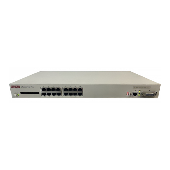
Page 20: Front And Back Panel Components
Front and Back Panel Components Front and Back Panel Components The following sections describe the front and back panel components for both the DECserver 716 and DECserver 732. Front Panel Components Table 1-1 describes the front panel components, and LEDs, that are illustrated in Figure 1-1. - Page 21 Seven-segment Display Provides error and status information. Blinks: If an error occurs during self-test. Off: The DECserver 716 or 732 has failed self-test. Rotating Figure’8’: Operating image loaded and running. 10BASE-T and AUI Allows you to switch between the 10BASE-T and AUI port selector switch on the server.
-
Page 22: Back Panel Components
Front and Back Panel Components Back Panel Components Table 1-2 describes back panel components that are illustrated in Figure 1-2. Figure 1-2: Back Panel Components DECserver 716 DECserver 732 3505-04 Table 1-2: Back Panel Component Descriptions Item Name Description Expels hot air from inside the DECserver. -
Page 23: Installing Brackets On The Decserver
Installing Brackets on the DECserver Overview Introduction This chapter describes how to install the DECserver 716 and DECserver 732 in a rack- mount cabinet and how to cable the front panel. NOTE The term DECserver is used where information is common to both the DECserver 716 and the DECserver 732. -
Page 24: Required Tools
CAUTION Static electricity can damage servers and electronic components. Digital Networks recommends using a grounded antistatic wrist strap and a grounded work surface when handling any servers. Check the shipment for damaged and missing parts. In case of damaged or missing parts, contact your delivery agent and your sales representative. -
Page 25: Installing The Rack-Mounting Brackets To The Decserver
Installing the Rack-Mounting Brackets to the DECserver Installing the Rack-Mounting Brackets to the DECserver The DECservers can be used as standalone devices or installed in a standard 19-inch rack using the rack-mounting kit part number 9061218. Table 2-1 describes how to assemble the rack-mounting kit as illustrated in Figure 2-1. -
Page 26: Installation Components
Installation Components Installation Components The following lists installation components including the connecting cables. • Brackets. For optional wall-mounting hardware, refer to Wiring and Connectivity selection on the web page: www.dnpg.com/products. • Serial line connection. For a list of supported cables refer to Chapter 4 or Appendix B. -
Page 27: Installing And Removing The Flash Ram Card
Overview Introduction This chapter describes how to install and how to remove the Flash RAM card from a DECserver 716 or DECserver 732. NOTE The term DECserver is used where information is common to both the DECserver 716 and the DECserver 732. -
Page 28: About The Flash Ram Card
About the Flash RAM Card About the Flash RAM Card Use the Flash RAM card to store the DECserver operational software, which can then be used to load the DECserver rather than using a load host available on the LAN. The Flash RAM may be updated with later releases of operational software. -
Page 29: Installing The Flash Ram Card In The Decserver
Installing the Flash RAM Card in the DECserver Installing the Flash RAM Card in the DECserver Figure 3-1 shows the Flash RAM card being inserted into the DECserver. Table 3-1 describes how to insert the Flash RAM card. Figure 3-1: Flash RAM Card Installation Table 3-1: Flash RAM Card Installation Procedures Step Action... -
Page 30: Removing The Flash Ram Card From The Decserver
Removing the Flash RAM Card from the DECserver Removing the Flash RAM Card from the DECserver The Flash RAM card can be hot swapped and may be removed at anytime. Figure 3-2 shows the Flash RAM card being removed from the DECserver. Table 3-2 describes how to remove the Flash RAM card. -
Page 31: Cabling Requirements
Overview Introduction This chapter describes communication distances and cable length requirements between associated devices and the DECserver 716 or DECserver 732. NOTE The term DECserver is used where information is common to both the DECserver 716 and the DECserver 732. -
Page 32: Connecting The Ethernet Cables And Devices
Connecting the Ethernet Cables and Devices Connecting the Ethernet Cables and Devices You can connect the DECserver to: • Standard Ethernet/IEEE 802.3 network • l0BASE-T Ethernet/IEEE 802.3 network 4-2 Cabling Requirements... -
Page 33: Connecting Serial Cables And Devices On The Decserver
Connecting Serial Cables and Devices on the DECserver Connecting Serial Cables and Devices on the DECserver The DECserver can be configured by the software to support one of the two sets of modem signals. One modem set consists of: • Clear to send (CTS)-This is the default setting. - Page 34 Connecting Serial Cables and Devices on the DECserver Cables and Adapters for the DECserver Table 4-1: Cable and Adapters Description BN24H The BN24H is a three twisted-pair cable with a standard 8- 8-Pin MJ to 6-Pin MMP Pin modular plug (DEC-423) on one end and a 6-Pin Office Cable MMP (modified modular plug) on the other.
-
Page 35: Cabling Requirements
Cabling Requirements Cabling Requirements Table 4-2 shows the maximum communication distances for different types of cables used between the DECserver and the Ethernet device. Table 4-3 shows the maximum cable lengths for a number of data rates using DECserver supported line protocols. The cabling requirements of the DECserver are shown in the following sections. -
Page 36: Standard Ethernet Connection Requirements
Cabling Requirements CAUTION Do not use structured building wiring or bundled type breakout cables at baud rates above 38.4K. Separate point to point cables are recommended at baud rates above 38.4K. Standard Ethernet Connection Requirements The transceiver cable must not exceed the maximum distances listed in Table 4-2. 10BASE-T Ethernet Connection Requirements The 10BASE-T Ethernet installation must conform to the following configuration rules:... -
Page 37: Connecting And Removing Cables And Adapters
Introduction This chapter describes how to connect cables to and remove cables from the DECserver 716 or DECserver 732. For cable lengths, refer to Chapter 4, Cabling Requirements. For information on connectors, refer to Appendix B, Connector and Pin Assignments. - Page 38 Topic Page Removing the 8-Pin MJ Cable 5-11 Removing the 10BASE-T Cable 5-12 Removing the Ethernet AUI Adapters 5-13 Removing Cables from the Ethernet AUI Adapters 5-14 Removing the Power Cable 5-17 5-2 Connecting and Removing Cables and Adapters...
-
Page 39: Connecting The Console Cable
Connecting the Console Cable Connecting the Console Cable This section describes how to connect the console cable to the DECserver. Connecting the 8-Pin MJ Console Cable Figure 5-1 shows how to connect the 8-Pin MJ console cable to Port 1 on the DECserver. -
Page 40: Connecting Cables
Connecting Cables Connecting Cables This section describes how to connect cables to the DECserver. Connecting the 8-Pin MJ Cable Figure 5-2 shows how to connect the 8-Pin MJ cable to ports on the DECserver. Figure 5-2: Connecting the 8-Pin MJ Cable To connect the cable, complete the following steps: 8-Pin MJ... -
Page 41: Connecting The 10Base-T (Utp) Cable
Connecting Cables Connecting the 10BASE-T (UTP) Cable The DECserver 10BASE-T uses an 8-pin MJ connector. Select the appropriate cable type, crossover or straight-through, to ensure that the server’s transmit/receive signals connect correctly to the transmitter/receiver of the connected device. Before connecting the cables to the server (Figure 5-3), note the following: Device Cable... -
Page 42: Connecting The Ethernet Aui Adapters
Connecting Cables Connecting the Ethernet AUI Adapters Figure 5-4 shows how to connect a 15-Pin AUI adapter to the AUI port on the DECserver. Figure 5-4: Connecting the AUI Adapters 3505-26 To connect an adapter, complete the following steps: Step Action Align the AUI adapter (1) with the AUI port (2). -
Page 43: Cabling The Ethernet Aui Adapters
Connecting Cables Cabling the Ethernet AUI Adapters This section describes how to connect the 15-Pin AUI adapters. Cabling the AUI Fiber Port Adapter Figure 5-5 shows how to cable the 15-Pin AUI fiber port adapters. Figure 5-5: Cabling the AUI Fiber Port Adapter 3505-28 To cable an adapter, complete the following steps: Step... - Page 44 Connecting Cables Cabling the AUI 10BASE-T Port Adapter Figure 5-6 shows how to cable the 15-Pin AUI 10BASE-T port adapters. Figure 5-6: Cabling the AUI 10BASE-T Port Adapter 3505-29 To cable an adapter, complete the following steps: Step Action Align the 10BASE-T connector (1) with the port on the AUI adapter (2). Ensure that the locking tab is positioned properly in relation to the 10BASE-T connector on the AUI adapter.
- Page 45 Connecting Cables Cabling the AUI BNC Port Adapter Figure 5-7 shows how to cable the 15-Pin AUI BNC port adapters. Figure 5-7: Cabling the AUI BNC Port Adapter 3505-37 To cable an adapter, complete the following steps: Step Action To install the T-connector (2): a.
-
Page 46: Connecting The Power Cable
Connecting Cables Connecting the Power Cable Figure 5-8 shows how to apply power to the DECserver. Figure 5-8: Connecting Power Cable 3505-15 To connect the power cable on the DECserver, complete the following steps: Step Action Plug the ac power supply cable (2) into the server power cable receptacle (1). -
Page 47: Removing The Cables
Removing the Cables Removing the Cables This section describes how to remove cables attached to the DECserver. Removing the 8-Pin MJ Cable Figure 5-9 shows how to remove 8-Pin MJ cables from ports on the DECserver. Figure 5-9: Removing the 8-Pin MJ Connector To remove the cable, complete the following steps: 8-Pin MJ... -
Page 48: Removing The 10Base-T Cable
Removing the Cables Removing the 10BASE-T Cable Figure 5-10 shows how to remove the 10BASE-T cable from the DECserver. Figure 5-10: Removing the 10BASE-T Cable 3505-19 To remove the 10BASE-T cable, complete the following steps: Step Action Press in the release tab on the cable plug (1), remove the connector from the DECserver 10BASE-T port connector (2). -
Page 49: Removing The Ethernet Aui Adapters
Removing the Cables Removing the Ethernet AUI Adapters Figure 5-11 shows how to remove a 15-Pin AUI adapter from the AUI port on the DECserver. Figure 5-11: Removing the AUI Adapters 3505-27 To remove the adapters, complete the following steps: Step Action Slide the locking tab (2) up (if the server is in the vertical position) or to... -
Page 50: Removing Cables From The Ethernet Aui Adapters
Removing the Cables Removing Cables from the Ethernet AUI Adapters This section describes how to remove the various cables from the 15-pin AUI adapters. Removing Cables from the AUI Fiber Port Adapter Figure 5-12 shows how to remove cables from the 15-Pin AUI fiber port adapters. Figure 5-12: Removing AUI Fiber Port Adapter Cables 3505-31 To remove the cable from an adapter, complete the following steps:... - Page 51 Removing the Cables Removing Cables from the AUI 10BASE-T Port Adapter Figure 5-13 shows how to remove cables from the 15-Pin AUI 10BASE-T port adapters. Figure 5-13: Removing AUI 10BASE-T Port Adapter Cables 3505-32 To remove the cable from the adapter, complete the following steps: Step Action Press in the release tab on the 10BASE-T connector (1), remove the...
- Page 52 Removing the Cables Removing Cables from the AUI BNC Port Adapter Figure 5-14 shows how to remove cables from the 15-Pin AUI BNC port adapters. Figure 5-14: Removing AUI BNC Port Adapter Cables 3505-37 To remove the cable from the adapter, complete the following steps: Step Action Turn the BNC connector (1) to the left to unlock the connector from the...
-
Page 53: Removing The Power Cable
Removing the Cables Removing the Power Cable Figure 5-15 shows how to remove power from the DECserver. Figure 5-15: Removing Power Cable 3505-15 To remove the power cable on the DECserver, complete the following steps: Step Action Remove the ac power supply cable (2) from the wall outlet. Remove the ac power supply cable from the DECserver power connector (1). -
Page 55: Overview
Problem Solving Overview Introduction This appendix helps you identify and correct problems you may encounter during and after the installation of the DECserver 716 or DECserver 732 hardware. The troubleshooting procedures are for diagnosing and correcting hardware-related problems only. NOTE The term DECserver is used where information is common to both the DECserver 716 and the DECserver 732. -
Page 56: Diagnosing Problems
Diagnosing Problems Diagnosing Problems Notify the network manager if the troubleshooting procedures indicate the problem is software related or if the procedures do not correct the problem. Additional software troubleshooting information is provided in the Network Access Software Problem Solving Guide. Use the following to diagnose and troubleshoot the DECserver problems: •... - Page 57 Diagnosing Problems Table A-1: Display/Indications Corrective Device Definition State Indication Action Page # System OK Diagnostic Self-test passed Fatal error Flashing Nonfatal error Seven- Status/ No power or Segment Diagnostic display broken Display “C”, “d”, “n” DRAM failure Flashing Fatal error “3”...
-
Page 58: Seven-Segment Display Off And System Ok Led Off
Seven-Segment Display Off and System OK LED Off Seven-Segment Display Off and System OK LED Off Ethernet LED Display Selected Power is not 1. Secure the power cable at the DECserver and at the wall reaching the outlet and check the fuse in the power cable plug (if DECserver applicable). -
Page 59: System Ok Led Off/Seven-Segment Display Flashing "C", "D", Or "N
System OK LED Off/Seven-Segment Display Flashing “C”, “d”, or “n” System OK LED Off/Seven-Segment Display Flashing “C”, “d”, or “n” Problem: The DECserver DRAM is faulty. Correction: There is no corrective procedure for this problem. Notify the network manager that the DECserver must be returned to Digital Network Products Group for repair or replacement. -
Page 60: System Ok Led Off/Seven-Segment Display Flashing
System OK LED Off/Seven-Segment Display Flashing System OK LED Off/Seven-Segment Display Flashing Problem: A hardware error occurred that makes the DECserver nonoperational. Correction: There is no corrective procedure for this problem. Notify the network manager that the DECserver must be returned to Digital Network Products Group for repair or replacement. -
Page 61: System Ok Led Flashing
System OK LED Flashing System OK LED Flashing If the System OK LED is flashing after power up, it indicates that the DECserver has a nonfatal problem detected during self-test. The error message on the console terminal shows the primary problem. To isolate and diagnose the problem, do the following: Step Action... - Page 62 System OK LED Flashing Message: Local—941—Transceiver loopback error Problem: The Ethernet port has failed self-test. Correction: Determine which of the following corrections applies to your situation: Check to ensure that the Ethernet selector switch is selecting the appropriate connector. Standard Ethernet/ThinWire – Replace the cables or MAU. Test again by pulling out the power cord and reinserting.
- Page 63 System OK LED Flashing Message: Local—967—Parameter checksum error detected in NVRAM Problem: Self-test has detected a checksum error in nonvolatile random-access memory (NVRAM) parameters. Correction: Reset the DECserver to the factory settings by pulling out the power cord and reinserting it while pressing the system reset switch until the System OK LED flashes.
-
Page 64: Seven-Segment Display Shows A "3
Seven-Segment Display Shows a “3” Seven-Segment Display Shows a “3” If the seven-segment display has a “3” after power up, the DECserver has a downline loading problem. To isolate and diagnose the problem, do the following: Step Action Connect a terminal to the console port of the DECserver, then power up the terminal. -
Page 65: Downline Load Does Not Start
Seven-Segment Display Shows a “3” Downline Load Does Not Start Message: The following sequence of messages appears on the console terminal at various time intervals: Local—951—Network DECserver will retry operation in n seconds Local—953—[IP] Attempting to locate load host, [ETHERNET] Local—953—[MOP] Attempting to locate load host, [ISO8802] Local—953—[MOP] Attempting to locate load host, [ETHERNET] Problem:... -
Page 66: Seven-Segment Display Codes
Seven-Segment Display Codes Seven-Segment Display Codes Table A-2 defines the seven-segmnet display codes (in approximate font type) and describes the codes that will be displayed during the server internal self-test when the DECserver goes through a power up and initialization. Table A-2: Seven-Segment Display Codes No power or display broken Initial power on... -
Page 67: Network Activity Led
Network Activity LED Network Activity LED Table A-3 shows the connection status for the Network Activity LED display. Table A-3: Network Activity LED Ethernet Connection Status LED Display Selected 10BASE-T Open/incorrectly terminated Correctly terminated Standard Ethernet A-13... -
Page 69: B Connector And Pin Assignments
Overview Introduction This chapter describes the cable pins of the DECserver 716 or DECserver 732. It also describes the hardware connectors and the cables used to interface to the DECserver hardware . Wiring diagrams of the individual cables are included to help you troubleshoot and in cable building. -
Page 70: Connector Pin Descriptions
Connector Pin Descriptions Connector Pin Descriptions This section describes the pins for the following DECserver connectors: • Standard Ethernet/IEEE 802.3 transceiver interface • 10BASE-T Ethernet/IEEE 802.3 transceiver interface • DECserver serial port connectors... -
Page 71: Standard Ethernet
Connector Pin Descriptions Standard Ethernet shows how the pins are numbered on a standard Ethernet transceiver Figure B-1 interface connector. lists the signals for the standard Ethernet connector Table B-1 pins. Figure B-1: Pin Numbers and Signals for Standard Ethernet Connector Table B-1: Signal Names for Standard Ethernet Connector Pins Pin No. -
Page 72: 10Base-T Ethernet
Connector Pin Descriptions 10BASE-T Ethernet The 10BASE-T Ethernet connector is an 8-Pin modular jack (MJ8). Figure B-2 shows how the pins are numbered on a 10BASE-T Ethernet connector and Table lists the signals for the 10BASE-T Ethernet connector. Figure B-2: Pin Numbers and Signals for 10BASE-T Ethernet Connector Table B-2: Signal Names for 10BASE-T Ethernet Connector Pins... -
Page 73: Decserver 8-Pin Mj Ports
Connector Pin Descriptions DECserver 8-Pin MJ Ports The DECserver uses an 8-Pin MJ connector on the serial ports. Figure B-3 shows how the pins are numbered on the 8-Pin MJ connector and Table B-3 lists the signals on the pins. You can set pins 4, 5, and 8 to either CTS, RTS, DSR or RI, DSRS, DCD. Figure B-3: Pin Numbers and Signals for the 8-Pin MJ Connector Table B-3:... -
Page 74: Cabling And Adapters Used With Decserver
Cabling and Adapters Used with DECserver Cabling and Adapters Used with DECserver Figure B-4 illustrates cabling (and adapters) that can be used with the DECserver. Note: For cables and adapters connections refer to Table 4-1 in Chapter 4. Figure B-4: Crossover and Straight-Through Cable Connections. - Page 75 Cabling and Adapters Used with DECserver Figure B-5 shows the crossover cable connection that can be used when cabling the 10BASE-T or 8-Pin MJ to the DECserver. Figure B-5: 10BASE-T and 8-Pin MJ Crossover Cable Connection.
-
Page 77: C Product Specifications
Overview Introduction The DECserver 716 or DECserver 732 can operate in an office environment and in a standard equipment rack located in a computer room or satellite equipment room. Regardless of where you install the DECserver, verify that all of the requirements in this section are met before beginning the installation. -
Page 78: Physical Requirements
Physical Requirements Physical Requirements Allow for 15 cm (6 in) of airspace around the DECserver air vents. Table C-1 shows the size and weight of the DECserver. Table C-1: Physical Specifications of the DECserver Dimension Measurement Height 43.69 mm (1.72 in) Width 438.15 mm (17.25 in) Depth... -
Page 79: Environmental Requirements
Environmental Requirements Environmental Requirements Environmental requirements for temperature and humidity must be within the ranges shown in Table C-3. Table C-3: Environmental Specifications of the DECserver Parameter Minimum Maximum Temperature Operating C (41 C (122 Nonoperating - 40 C (- 40 C (151 Maximum rate of C (36... -
Page 80: Electrical Requirements
Electrical Requirements Electrical Requirements The power at the electrical outlet must match the requirements shown in Table C-4. The instructions assume that an appropriate ac power source is within 1.8 m (6.0 ft) of DECserver. Table C-4: Electrical Requirements Parameter DECserver Line voltage 100–120 V rms/220–240 V rms... - Page 81 10BASE-T Link LED 1-5 10BASE-T Port connection 1-5 DECserver 8-pin MJ Ports B-5 Back Panel Components 1-6 Front Panel Components 1-4 DECserver 716 and 732 Overview 1-2 AUI Port 1-5 Diagnosing Problems A-2 AUI Selection LED 1-5 Documentation related documents xv...
- Page 82 Environmental C-3 Physical C-2 Reset Switch 1-4 Seven-Segment Display Codes A-12 Error Messages A-7 Off and System OK LED Off A-4 Status LEDs 1-5 Switch 10BASE-T and AUI 1-5 Reset 1-4 What are the DECserver 716 and 732 1-2 Index-2...
- Page 84 Digital Networks IG-DSRVW-00...
Need help?
Do you have a question about the DECserver 716 and is the answer not in the manual?
Questions and answers