Dormakaba ED50 Installation Instructions Manual
Low energy automatic swing door operator, installation in surface applied (narrow) header
Hide thumbs
Also See for ED50:
- Installation instructions manual (116 pages) ,
- Manual (74 pages) ,
- Owner's manual (20 pages)

Related Manuals for Dormakaba ED50


Summary of Contents for Dormakaba ED50
- Page 1 ED50 Low Energy Automatic Swing Door Operator Installation in Surface Applied (Narrow) Header Installation Instructions DL4615-002 – 01-2020 | EN |...
-
Page 2: Table Of Contents
Door signage, low energy single swing 14.5 Remove protective film strips from door operator 11.3 Door signage, low energy double swing 14.6 Install ED50 operator on mounting plate doors in header 11.4 Safety label, low energy swing doors 14.7 Double header ED50 operator installation 14.8... - Page 3 ED50 SA Installation Instructions Table of Contents Arm with track mount installation Install door signage 15.1 Arm with track installation 28.1 Install door signage ANSI/BHMA standards 15.2 Splined arm and track assemblies 15.3 Splined arm and track hardware 29.1 A156.19 Low energy power operated...
-
Page 4: General Information
Chapter 1 1 General information 1.1 Installation Instructions. This manual provides installation instructions for ED50 low energy operators used in single door and double door surface applied installations. 1.2 Manual storage. This document must be kept in a secure place, and accessible for reference as required. -
Page 5: Product Description
ED50 operators. Included inside header: • (2) low energy accessory installation kits WARNING (Chapter 6). To reduce risk of injury to persons, use this ED50 • Program switch panel (Chapter 5). operator only with a swing door for which the •... -
Page 6: Safety Information
Crushing hazards at door closing edges! Standard for Power Assist and Low Energy Power Operated Doors shall be applied and maintained on the door controlled by the ED50 low energy operator. Fig. 3.1 Door closing edges 3.3 Safety warnings. WARNING... -
Page 7: Recommended Tools And Torque Chart
ED50 SA Installation Instructions Chapter 4 4 Recommended tools and torque chart Recommended tools Fig. 4.1.1 Recommended tools T-handle hex key, 5 mm Hex keys, 2.5 mm, 3 mm, 6 mm Screwdriver, flat blade Door pressure gauge, 0 to 35 ft - lbf... -
Page 8: Ed50 Product Overview
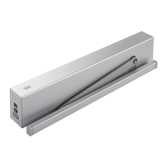
ED50 SA Installation Instructions Chapter 5 5 ED50 Product overview ED50 operator Fig. 5.1.1 ED50 operator ED50 header ED50 operator Mounting plate Push arm Terminals for accessory wiring Bag containing terminals and third Fig. 5.1.2 Accessory terminals, guide pin... -
Page 9: Ed50 Single Swing Door Header
Fig. 5.5.1 Double header with cover Double header Header cover Cover screws Program switch panel Hole for drive axle Header track Hole for spring Fig. 5.5.2 Double header without ED50 operators tension adjustment Fig. 5.5.3 Double header with ED50 operators ED50 DL4615-002 01-2020... -
Page 10: Ed50 Operator Component Views
SA ED50 Installation Instructions Chapter 4 ED50 operator component views Fig. 5.6.1 ED50 component views Power switch 120 Vac cable Housing unit Drive spindle Operator (motor, gear, spring) Spring tension adjustment, closing force Brake 4 button user interface Information... -
Page 11: Axle Extensions
ED50 SA Installation Instructions Chapter 4 Axle extensions Fig. 5.7.2 [30 mm] Fig. 5.7.1 [20 mm] Fig. 5.7.3 [60 mm] 1 1/8" 3/4" 2 3/8"" 20 mm axle extension sleeve 25447200140 30 mm axle 20 mm axle extension sleeve... -
Page 12: Push Arm Door Stop - Option
SA ED50 Installation Instructions Chapter 4 Push arm door stop - option Fig. 4.9.1 Door stop assembly Fig. 4.9.2 Mounting screw kit 1/2" thick base plate DC4633-002 1/4" thick base (4) 5.1 plate DC4633-001 Rubber bumper DC4633-003 Shoulder screw DC4633-004 1/4 x 1 1/4"... -
Page 13: Double Door Ed50 Operator Connection Cables
Program switch panel DX4604 Manuals not shown. Installation manual Owner's manual Optional key switch panels; Reference Para. 5.3. Double door ED50 operator connection cables Fig. 6.2.1 Communication cable Fig. 6.2.2 115 VAC power cable Communication cable DX3485-010, 250 mm, 9 7./8"... -
Page 14: Technical Data
ED50 SA Installation Instructions Chapter 7 7 Technical data ED50 Technical data 7.1.4 Outputs Maximum wire size 7.1.1 Required operating conditions 16 AWG Connector plug 1/16” screw size Ambient temperature 5 to 122 °F Sr parameter Suitable for dry... -
Page 15: Operating Specifications
Appendix A, Parameter detail Low energy product 8.2.1 ANSI/BHMA 156.19 Required system safety, as a low energy application, is ED50 operator is configured to meet requirements of a achieved utilizing the following design factors: low energy application per ANSI/BHMA A156.19 •... -
Page 16: User Interface
ED50 SA Installation Instructions Chapter 9 9 User interface Overview Fig. 9.1.1 Operator keypad and display 9.1.1 Operator user interfaces 2 digit display 1. 4 button keypad and 2 digit display. 4 button keypad • 4 button keypad; to select, input and adjust door parameter values. -
Page 17: Program Switch Panel
SA ED50 Installation Instructions Chapter 9 9.3.1 Program switch control modes Program switch panel • Auto, door opens following pulse generation by a knowing act device or by Fig. 9.3.1 Program switch panel push/pull. • Close, door closes automatically, or Program switch remains closed. -
Page 18: System Accessories
Door locking device Manual release switch ED50 header 10.2 System accessories 10.2.1 Overview 10.2.6 Activators ED50 operators are normally used with Typical activators: system accessories available from 1. Pushbuttons, key switches dormakaba USA, Inc. or other 2. Access control systems manufacturers. -
Page 19: Ed50 Terminal Board Interfaces
SA ED50 Installation Instructions Chapter 10 10.3 ED50 terminal board interfaces Fig. 10.3.1 Terminal board electrical connections Green LED (Para. 9.4) Night- Activation inputs Yellow LED (Para. 9.4) Interior Exterior bank Safety sensors input Red LED (Para. 9.4) DCW bus... -
Page 20: Ed50 Door Signage
ED50 SA Installation Instructions Chapter 11 11 ED50 door signage 11.1 Low energy operator 11.2 Door signage, low energy single swing door 11.1.1 Overview Signage and warnings are specified in ANSI /BHMA Fig. 11.2.1 Knowing act device initiation of door operation A156.19, American National Standard for Power Assist... -
Page 21: Door Signage, Low Energy Double Swing Doors
ED50 SA Installation Instructions Chapter 11 11.3 Door signage, low energy double swing doors Fig. 11.3.1 Knowing act, SA header side Fig. 11.3.2 Knowing act, hinge side AUTOMATIC AUTOMATIC AUTOMATIC AUTOMATIC CAUTION CAUTION CAUTION CAUTION DOOR DOOR DOOR DOOR... -
Page 22: Safety Label, Low Energy Swing Doors
ED50 SA Installation Instructions Chapter 11 11.4 Safety label, low energy swing Fig. 11.4.1 Safety label Fig. 11.4.2 Annual compliance label doors SAFETY INFORMATION Low Energy Swinging 11.4.1 Low energy swinging door safety information ANNUAL COMPLIANCE Doors label INSPECTION... -
Page 23: 12.1 Ed50 Sa Arm Configurations
SA ED50 Installation Instructions Chapter 12 12 ED50 SA arm configurations 12.1 Single swing door right hand arm configurations Fig. 12.1.1 RH pull Pull arm Track Fig. 12.1.2 RH deep pull Track Pull arm with CPD lever Fig. 12.1.3... -
Page 24: 12.2 Single Swing Door Left Hand Arm
ED50 SA Installation Instructions Chapter 12 Fig. 12.1.5 RH deep push Deep push arm Door stop (optional) 12.2 Single swing door left hand arm configurations Fig. 12.2.1 LH pull Pull arm Track Fig. 12.2.2 LH deep pull Track Pull arm with CPD lever Fig. -
Page 25: Single Swing Door Center Hung Door Arm
SA ED50 Installation Instructions Chapter 12 Fig. 12.2.4 LH push Push arm Door stop (optional) Fig. 12.2.5 LH deep push Deep push arm Door stop (optional) 12.3 Single swing door center hung door arm configurations Fig. 12.3.1 Center hung door, RH push arm Fig. - Page 26 ED50 SA Installation Instructions Chapter 12 Fig. 12.3.5 Center hung door, LH pull arm Fig. 12.3.3 Center hung door, RH pull arm Track Pull arm with CPD lever Bottom pivot assembly (by others) Fig. 12.3.6 Center hung door, pull as push RH Fig.
-
Page 27: Double Door Arm Configurations
SA ED50 Installation Instructions Chapter 12 12.4 Double door arm configurations Fig. 12.4.1 Double door pull Pull arm Track Fig. 12.4.2 Double door deep pull Track Pull arm with CPD lever Fig. 12.4.3 Double door pull as a push... -
Page 28: Double Egress Arm Configurations
ED50 SA Installation Instructions Chapter 12 12.5 Double egress arm configurations Fig. 12.5.1 Double egress LH Track Pull arm with CPD lever Push arm Fig. 12.5.2 Double egress RH Track Pull arm with CPD lever Push arm ED50 DL4615-002... -
Page 29: 12.6 Double Door Center Hung Arm
SA ED50 Installation Instructions Chapter 12 12.6 Double door center hung arm configurations Fig. 12.6.1 Center hung door, double door pull Track Pull arm with CPD lever Bottom pivot assembly (by others) Top pivot assembly (by others) not shown Fig. -
Page 30: 13 Header Installation
Structural, local conditions, available tools, or other factors or circumstances WARNING may require modification to these steps. ED50 header assembly should be installed by trained and knowledgeable installers WARNING experienced in installation and commissioning Operator 115 Vac branch circuit disconnect must of automatic door closers. -
Page 31: 13.3 Remove Ed50 Operator From Mounting
ED50 SA Installation Instructions Chapter 13 13.3 Remove ED50 operator from mounting plate Fig. 13.3.1 Operator M6 SHCS locations Fig. 13.3.2 M6 x 10 SHCS ED100 / ED250 operator Mounting base M6 X 20 SHCS M6 X 10 SHCS... -
Page 32: Single Header Installation
ED50 SA Installation Instructions Chapter 13 13.4 Single header installation 13.4.1 Single header installation preparation Fig. 13.4.1 Door frame width 1. Door frame installed. Header width 2. Confirm header width. • Header width equals door frame width plus three inches. -
Page 33: Install Program Switch Panel In Header
ED50 SA Installation Instructions Chapter 13 Fig. 13.4.4 Header located on door frame Screws in bottom slide channel Screws in top V-groove (located on stud centerlines) Program switch panel (may be in different location) Low voltage wiring 115 Vac wiring (may... -
Page 34: Double Header Installation
ED50 SA Installation Instructions Chapter 13 13.6 Double header installation Fig. 13.6.1 Header and door frame width 13.6.1 Double header installation preparation 1. Door frame installed. Header width 2. Confirm header width. Door frame width • Header width equals door frame width plus three inches. - Page 35 ED50 SA Installation Instructions Chapter 13 Fig. 13.6.3 Header located on door frame/wall Screws in bottom Low voltage and slide channel 115 Vac wiring (may Screws in top be in different V-groove (located on location) stud centerlines) Program switch...
-
Page 36: 13.7 Sa Narrow Header (4 X 6") - Push Arm Template
ED50 SA Installation Instructions Chapter 13 13.7 SA narrow header (4 x 6") – push arm template Fig. 13.7.1 Standard push arm template 0 to 8 3/4” Reveal depth 90° 20 1/16” [510] Header width = door width + 3”... -
Page 37: Sa Narrow Header (4 X 6")
ED50 SA Installation Instructions Chapter 13 13.8 SA narrow header (4 x 6") – deep push arm installation template Fig. 13.8.1 Deep push arm template 90° Reveal depth 26 5/16” [667] Header width = door width + 3” [76.2] 5 7/8”... -
Page 38: Sa Narrow Header (4 X 6")
ED50 SA Installation Instructions Chapter 13 13.9 SA narrow header (4 x 6") – pull arm template Fig. 13.9.1 Deep pull arm template 5 7/8” 1 1/2” 1 1/2” [38] [149] [38] 2” [48] 3/4” [19] 17 3/4” 7”... -
Page 39: Sa Narrow Header (4 X 6") - Deep Pull Arm Template
ED50 SA Installation Instructions Chapter 13 13.10 SA narrow header (4 x 6") – deep pull arm template Fig. 13.10.1 Deep pull arm template 1 1/2” 5 7/8” [38] [147] 3 7/8” [99] 1 1/8” 7” 17 3/4” [178]... -
Page 40: Sa Narrow Header (4 X 6") - Center Hung Door, Push Arm Template
ED50 SA Installation Instructions Chapter 13 13.11 SA narrow header (4 x 6") – center hung door, push arm template Fig. 13.11.1 Push arm template 2 3/4” [70] 16” [413] 90° 5 7/8” 1 1/2” [149] [37] 1/2” [13] 1 1/2”... - Page 41 ED50 SA Installation Instructions Chapter 13 13.12 SA narrow header (4 x 6") offset pivot door, ,push arm template Fig. 13.12.1 Offset pivot door, surface applied header, push arm template 2 3/4” [70] 5 3/4” 1 1/2” [38] [147] 2 3/8”...
- Page 42 ED50 SA Installation Instructions Blank page This page left intentionally blank. ED50 DL4615-002 01-2020...
- Page 43 ED50 SA Installation Instructions Blank page This page left intentionally blank. ED50 DL4615-002 01-2020...
-
Page 44: 14 Ed50 Operator Installation
ED50 SA Installation Instructions Chapter 14 14 ED50 operator installation 14.1 Single header mounting plate installation Fig. 14.1.1 Header with header tracks Header track Operator axle hole Program switch panel Fig. 14.1.2 Mounting plate Mounting plate 2 (12) 1/4 x 20 UNC hole... -
Page 45: Double Header Mounting Plate Installation
ED50 SA Installation Instructions Chapter 14 14.2 Double header mounting plate installation Fig. 14.2.1 Double header with header tracks Axle centerline Program switch Header track panel Fig. 14.2.2 Double header with mounting plates installed Guide pin Third guide pin Fig. -
Page 46: Customer 115 Vac Connection To
Fig. 14.3.1 Mounting plate power connection side WARNING 115 Vac terminal block Routing and connection of 115 Vac Ground terminal wiring to ED50 must be performed Terminal block screw by a qualified person! torque label Preferred 115 Vac wiring entry point WARNING... -
Page 47: Double Door Header 115 Vac Mounting
ED50 SA Installation Instructions Chapter 14 14.4 Double door header 115 Vac mounting plate connection Fig. 14.4.1 Double door header 115 Vac connection 115 Vac terminal block Ground stud 14.4.1 115 VAC connection to double door NOTICE header. 1. Customer 115 Vac connects to mounting... -
Page 48: Install Ed50 Operator On Mounting Plate
ED50 SA Installation Instructions Chapter 14 14.6 Install ED50 operator on mounting plate in header Fig. 14.6.1 Header with mounting plate installed Guide pin Mounting plate 115 VAC plug M6 SHCS mounting hole Program switch Fig. 14.6.2 Installing operator on mounting plate... -
Page 49: 14.7 Double Header Ed50 Operator Installation
ED50 SA Installation Instructions Chapter 14 Fig. 14.6.5 Header with operator installed 14.7 Double header ED50 operator installation Fig. 14.7.1 Double header with operators installed 14.7.1 Install operators on mounting Fig. 14.7.2 115 Vac power cable installed on plates. -
Page 50: Connect Program Switch Cable To Ed50
ED50 SA Installation Instructions Chapter 14 14.8 Connect program switch cable to ED50 operator Fig. 14.8.1 Header with ED50 operator Program switch panel Header for program switch cable COM 1 service connector Fig. 14.8.2 Cable installation on operator Fig. 14.8.4 Program switch panel... - Page 51 ED50 SA Installation Instructions Blank page This page left intentionally blank. ED50 DL4615-002 01-2020...
-
Page 52: Arm With Track Mount Installation
ED50 SA Installation Instructions Chapter 15 15 Arm with track mount installation 15.1 Arm with track installation NOTICE Reference Para. 12.2 (single door) and Para. 12.3 (double door) installation templates. 15.2 Splined arm and track assemblies Fig. 15.2.1 Splined arm with CPD lever and Fig. -
Page 53: Slide Shoe Assembly
ED50 SA Installation Instructions Chapter 15 15.4 Slide shoe assembly 15.4.1 Install pivot pin into slide shoe. Fig. 15.4.1 Slide shoe and pivot pin 1. Insert pivot pin into slide shoe. Slide shoe Pivot pin 2. Install spring clip into pivot pin slot. -
Page 54: Fasten Track Assembly To Door
ED50 SA Installation Instructions Chapter 15 15.6 Fasten track assembly to door 15.6.1 Mount track assembly on door. Fig. 15.6.1 Track assembly example Track CAUTION Fixing piece Insure track hardware is Slide shoe assembled for hand of door. Bumper Wood screw 1. -
Page 55: Arm Assembly
ED50 SA Installation Instructions Chapter 15 15.7 Arm assembly Fig. 15.7.1 Arm assembly Aarm 15.8 Arm assembly with CPD extension 15.8.1 Arm with CPD extension assembly. Fig. 15.8.1 Slotted spring pin Slotted spring pin CAUTION Assemble arm and CPD lever based on RH or LH pull or push. -
Page 56: Fasten Arm To Ed50 Operator
ED50 SA Installation Instructions Chapter 15 15.9 Fasten arm to ED50 operator 15.9.1 Mount drive arm to operator. Fig. 15.9.1 Mount drive arm to operator at 12 degrees WARNING 12° Use caution when working in proximity of door and drive arm!. - Page 57 ED50 SA Installation Instructions Chapter 15 Fig. 15.9.6 Fastening drive arm to pivot pin 15.9.2 Attach drive arm to pivot pin. 1. Open door as required to access pivot pin M8 socket head. 2. Use 6 mm T handle hex key to rotate pivot pin M8 socket head into drive arm and tighten.
-
Page 58: Push Arm Installation Templates
ED50 SA Installation Instructions Chapter 16 16 Push arm installation 16.1 Push arm installation templates NOTICE Reference Chapter 13 for installation templates. Fig. 16.1.1 Push arm assemblies Standard push arm, reveal depths 0 - 8" maximum Deep push arm reveal depths 8 - 12"... -
Page 59: Assemble Drive Arm To Operator
Reference Chapter 19, Set operator spring tension. 2. Insert axle extension into drive arm. Splined drive arm Shoe 3. Move arm to ED50, inserting axle Socket Ball head extension sleeve into operator spindle at Adjustment arm a 90⁰ angle (Fig. 16.3.3). - Page 60 ED50 SA Installation Instructions Chapter 16 Fig. 16.3.5 Arm assemblies attached to door and ED50 16.3.4 Connect adjustment arm to drive arm. 1. Loosen the two adjustment M6 x 10 mm flanged button head screws (Fig. 16.3.5). 1. Using square, position adjustment arm assembly at 90⁰...
-
Page 61: Measure Door Width, Reveal Depth
ED50 SA Installation Instructions Chapter 17 17 Measure door width, reveal depth 17.1 Door width parameter Tb 17.3 Tb parameter values 17.3.1 ED50 door width Parameter Reference Description paragraph, Door width measurement parameters Width Inches [mm] inches Door width Para. -
Page 62: Reveal Depth Parameter Rd
Use of arm and CPD lever (Fig. 17.4.1): Value of parameter rd must be reduced by 3/16" [30]. Door frame • Example: ED50 with CPD pull arm and lever in pull installation with reveal of 30 mm (1 1/8"). Parameter rd setting = 0 Face of (Reveal of 30 mm - 30 mm). -
Page 63: Braking Circuit Plug
ED50 SA Installation Instructions Chapter 18 18 Braking circuit plug 18.1 Braking circuit plug position Fig. 18.1.1 Braking circuit socket and plug, plug factory installed in pull installation location Braking circuit plug Braking circuit 3 pin socket User interface 18.1.1 Braking circuit plug. -
Page 64: Operator Spring Tension
ED50 SA Installation Instructions Chapter 19 19 Operator spring tension 19.1 Set ED50 operator spring tension 19.1.2 Operator spring tension function. Fig. 19.1.1 Spring tension adjustment 1. Spring tension sets closing force on door. 2. Required spring tension is based on door width. -
Page 65: Power Fail Closing Speed
3/32" [2-3 mm] flat blade screwdriver required for adjustment. 20.1.2 Setting door closing speed upon power failure. 1. Turn ED50 power switch OFF. 2. Manually open door to 90° angle and let it close. 3. If door closes in less than 5 seconds, turn... -
Page 66: Parameters
Operator firmware version is displayed during first commissioning. Reference Chapter 22. Program switch, • dormakaba handheld can be used to check operator 3 position firmware version and to perform firmware updates. Reference Appendix C, dormakaba handheld, or dormakaba handheld manual. - Page 67 ED50 SA Installation Instructions Chapter 21 21.1.5 Configuration parameters TIPS AND RECOMMENDATIONS Parameter Description Driving parameter details can be found in Appendix A, Driving Parameters – detail. Installation type Reveal depth Driving parameter Description Door width Input 4/4a and X3, 1G 24V locking...
- Page 68 [Application specific]. installation. 1. For doors without fire or smoke detection • Example: ED50 with arm and CPD lever in pull requirements. installation with reveal of 30 mm (1 1/8"). 2. Maximum reveal depth of 2 3/8" [60]. Parameter rd setting = 0 (Reveal of 30 mm - 30 mm).
-
Page 69: Single Door First Commissioning
ED50 SA Installation Instructions Chapter 22 22 Single door first commissioning 22.1 First commissioning Fig. 22.1.1 Program switch Conditions prior to commissioning. Program switch, 3 position 1. Header with operator is installed. 2. Standard push arm or arm with track is installed. -
Page 70: Set Configuration Parameters
ED50 SA Installation Instructions Chapter 22 22.2 Set configuration parameters 22.2.1 Set parameter AS, installation type. Fig. 22.2.1 4 button keypad, 2 digit display Step 1 Press and hold PRG > 3 s to enter Four button Press program mode, AS parameter keypad displayed. -
Page 71: Key Switch Option; Set Parameter Ps Program Switch Type
CAUTION set parameter PS to 1. Key switch option – Step 1 Press and hold PRG > 3 s to enter Program switch wired to ED50 terminal Press program mode, AS parameter board. Reference Appendix D. displayed. Parameter PS (Program switch type) must be Step 2 set to 1. -
Page 72: Perform Learning Cycle
ED50 SA Installation Instructions Chapter 22 22.4 Perform learning cycle CAUTION Step 1 Secure motion range of door. Learning cycle must be performed while Step 2 Set program switch to CLOSE position. motor is cold! Rotating "o" and a "0" indicates CAUTION operator learning cycle is required. -
Page 73: Double Door First Commissioning
ED50 SA Installation Instructions Chapter 23 23 Double door first commissioning 23.1 Separately commission active and inactive doors 23.1.1 Commission active door first. 1. Refer to Para.21.1 and commission active door. 23.1.2 Commission inactive door. 1. Refer to Para.21.1 and commission inactive door. -
Page 74: Connect Communication Cable Between Operators
ED50 SA Installation Instructions Chapter 23 23.2.2 Inactive door, set parameter dL. 1. Set program switch to CLOSE. 2. Set parameter dL (door type) for inactive door. Step 1 Step 5 Press and hold PRG > 3 s to enter... -
Page 75: Set Track Bumper Stop
ED50 SA Installation Instructions Chapter 24 24 Set track bumper stop 24.1 Set track bumper stop position 24.1.1 Set bumper stop position. Fig. 24.1.1 Door at set opening angle, bumper stop set 1. Set program switch to OPEN. 2. Door moves to set opening angle. -
Page 76: Install Push Arm Door Stop
Chapter 25 dormakaba SA ED50 Installation Instructions 25 Install push arm door stop 25.1 Install push arm bumper stop (optional assembly) Fig. 25.1.1 Bumper stop assembly TIPS AND RECOMMENDATIONS 1/2" thick base plate Contact local dormakaba USA, DC4633-002 Inc. distributor for bumper stop (4) 5.1... -
Page 77: Install Header Cover
ED50 Installation Instructions Chapters 27 and 28 27 Install header cover 27.1 Install header cover. 27.1.1 Install header cover. 1. Install header cover on header and CAUTION secure with supplied flat head screws. Note: Headers with pull arms shown as an Before installing cover, check example. -
Page 78: 29.1 Ansi/Bhma Standards
ED50 SA Installation Instructions Chapter 29 29 ANSI/BHMA standards 29.1 A156.19 Low energy power operated doors The following table references portions of content from ANSI/BHMA A156.19. Refer to the standard, available through ANSI or BHMA for additional information. Standard material reprinted with BHMA permission. - Page 79 ED50 SA Installation Instructions Chapter 29 29.1.2 A156.19, Table I: Minimum opening and closing times. "W" door weight, pounds "D" door width, inches 3.0 s 3.0 s 3.0 s 3.0 s 3.5 s 3.0 s 3.5 s 3.5 s 4.0 s...
- Page 80 ED50 SA Installation Instructions Chapter 30 Fig. 30.1.2 Annual Fig. 30.1.1 Safety compliance information 30 Maintenance inspection label label ANNUAL COMPLIANCE SAFETY INFORMATION 30.1 Safety label, low energy swing INSPECTION Low Energy Swinging Doors INSPECT FOR AND doors COMPLIES WITH ANSI These minimum safety checks, A156.19 ON:...
- Page 81 DD0586-010 ACTIVATE SWITC H TO OPERATE DD0758-010 DD0758-010 dormakaba ED50 header can be cleaned with a damp cloth and commercial cleaning agents. TIPS AND RECOMMENDATIONS Abrasive (scouring) agents should not be used as they may damage header surfaces. 30.2.4 Water and other liquids.
- Page 82 ED50 SA Installation Instructions Chapter 30 30.4 Pull arm maintenance Fig. 30.4.1 Pull arm with track assembly, track mounting screws Fig. 30.4.3 Program switch 30.4.1 Track mounting screws. 1. Set program switch to CLOSE. 2. Remove track end caps 3.
- Page 83 ED50 SA Installation Instructions Chapter 30 30.4.1 Arm fasteners – torque requirements 30.4.1.1 Check drive arm M8 SHCS torque. Fig. 30.4.1.1 Spindle M8 SHCS 1. Set program switch to CLOSE. 2. Remove cap over M8 SHCS. 3. Check torque.
- Page 84 ED50 SA Installation Instructions Chapter 30 30.6 Push arm maintenance Fig. 30.6.1 Push arm assembly Fig. 30.6.4 Program switch 30.6.1 Push arm maintenance. WARNING Set program switch to CLOSE before performing maintenance! 1. Adjustment arm. • Check for wear or damage.
- Page 85 ED50 SA Installation Instructions Chapter 30 30.7 Push arm – M8 SHCS torque requirements 30.7.1 Drive arm M8 SHCS torque. Fig. 30.7.1 Push arm M8 SHCS 1. Remove spindle cap. 2. Check tightness of M8 SHCS. 3. Replace spindle cap.
-
Page 86: Ed50 Brake Maintenance
ED50 SA Installation Instructions Chapter 30 30.8 ED50 brake maintenance 30.8.1 Adjustment of air gap: Fig. 30.8.1 ED900 operator brake to brake disc (Fig. 30.8.2). TIPS AND RECOMMENDATIONS Reference drawing: 254197-01-50 WARNING Brake assembly Set program switch to CLOSE Fig. - Page 87 ED50 SA Installation Instructions Chapter 30 30.8.2 Torque setting of M3 x 5 SHCS. Fig. 30.8.5 M3 x 5 SHCS • 5.3 in-lb + 0.9 in-lb [0.6 Nm +0.1 Nm] Brake assembly Brake disc assembly M3 x 5 SHCS Fig.
-
Page 88: Appendix A - Driving Parameters
ED50 SA Installation instructions Appendix A Appendix A - Driving parameters Driving parameters – detail A.1.1 Driving parameters detail. Value Factory Parameter Units Description range setting Opening speed, automatic mode 1. Opening speed refers to automatic mode, speed can be adjusted using this parameter. - Page 89 ED50 SA Installation Instructions Appendix A A.1.1 Driving parameters detail. Value Factory Parameter Units Description range setting Safety sensor parameter ST must be set to sensors used and if they are active-high or active-low. See E 04 safety sensor test error, Appendix B.
- Page 90 .45- 3.4 1.35 See Chapter 29. 4. ED50 low energy operator: static force range is reduced. Static force in closing direction 1. Static force in closing direction (basic parameter for wind load control). Static force on door closing edge can be changed using this parameter.
- Page 91 ED50 SA Installation Instructions Appendix A A.1.1 Driving parameters detail. Value Factory Parameter Units Description range setting Push & Go 1. Parameter is activated. 2. Automatic opening of door is started when door is manually moved 4° out of the 0 - 1 closed position.
- Page 92 1. Status relay activated when door is opened further than opening angle parameter OA, set during learning cycle. 2. Parameter OA value can only be changed using dormakaba handheld or by performing another learning cycle. Locking device output configuration;...
- Page 93 Service interval is reset to 12 months. • Yellow LED not illuminated. 0 - 1 2. Parameter is then automatically reset to "0". 3. Values other than default values must be set using dormakaba USA, Inc. handheld: • Maintenance interval •...
- Page 94 ED50 SA Installation instructions Appendix A A.1.1 Driving parameters detail. Value Factory Parameter Units Description range setting 1. Automatic mode. This mode is applicable whenever door is mainly opened automatically and where motion detectors are installed. 2. Mode is optimized for high frequency use.
- Page 95 Key switch button ST 32 DCW (max. 2) • I/O module DCW (max. 1) COM 1 configuration interface Interface programmed for communication with dormakaba handheld. 0 - 1 Interface programmed for use with dormakaba TMS Soft control software. ED50 DL4615-002 01-2020...
- Page 96 ED50 SA Installation instructions Appendix A A.1.1 Driving parameters detail. Value Factory Parameter Units Description range setting Backcheck when door opened manually 1. Angle after which door is braked when manually opened. 2. Back check level is automatically optimized during manual door opening cycles. This...
- Page 97 ED50 SA Installation Instructions Appendix A Overhead concealed mode (OHC): Activation of permanent open via night-bank input Function disabled. 0 - 1 If night-bank signal is longer than 3 seconds, operator changes to permanent open mode. Overhead concealed mode (OHC):...
-
Page 98: Appendix B - Troubleshooting
Red LED operator will switch to emergency mode. Users can Yellow LED then access door manually. Green LED B.1.3 User information display. User interface display, or or dormakaba handheld displays: • Information ln codes • Error message E codes B.1.4 Viewing error messages. -
Page 99: Red Led Status Codes
ED50 SA Installation Instructions Appendix B B.1.7 Error message memory. 1. There are ten error message memory locations; E 0 through E 9. 2. The latest error message is always stored in error memory location E 0: • As soon as another error occurs, the existing error stored in E 0 will be moved to E 1 and the latest error will be stored in E 0. -
Page 100: Troubleshooting Chart, "Ln" Codes
3. If ln 08 still present, check activators or system wiring. Upgrade card error 1. Installed upgrade card cannot be removed from ED50. • Installed upgrade card has 2. If more than one upgrade card is installed, the first card installed becomes been removed. -
Page 101: Troubleshooting Chart, "E" Codes
4. Check for activation of the test at the safety sensors. EEPROM error • Internal memory check could 1. Using dormakaba handheld, reload current firmware to Flashing not be completed. reinitialize system. E 12 12 x •... - Page 102 ED50 SA Installation instructions Appendix B B.4.1 Troubleshooting chart, "E" codes. Display Red LED • Description Troubleshooting error codes Overcurrent detection 1. Motor is consuming too much power, check for any external • Motor is consuming more Flashing causes.
-
Page 103: Appendix C - Dormakaba Handheld
(dot, comma, hash key, plus, C.1.1 Interface cable minus, asterisk and diagonal slash). Use dormakaba interface cable (Article No. 16596101170) C.1.3 Handheld startup. to connect dormakaba handheld to operator 1. Press OFF ON to turn on Handheld terminal. -
Page 104: Dormakaba Handheld; Configuration
ED50 SA Installation instructions Appendix C NOTICE Parameters and detail may change depending on firmware version. dormakaba handheld; configuration parameters "#" refers to reference numbers in Parameter list, Chapter 18. C.2.1 Configuration parameters Parameter and Parameter and Description / Selections... -
Page 105: Dormakaba Handheld; Driving Parameters
ED50 SA Installation Instructions Appendix C C.2.1 Configuration parameters Parameter and Parameter and Description / Selections Description / Selections default default Manual mode on. NO contact; night- Manual bank function mode Normal* Manual mode disabled. triggered while contact closed. -
Page 106: Dormakaba Handheld; Special Functions
ED50 SA Installation instructions Appendix C dormakaba handheld; special functions (Upgrade cards) ED50 C.4.1 Special functions (upgrade cards) Parameter and Parameter and Description / Selection Description / Selection default default • locked: not available locked Upgrade • unlocked: available, not active... -
Page 107: Dormakaba Handheld; Diagnostics
ED50 SA Installation Instructions Appendix C dormakaba handheld; diagnostics C.5.1 Diagnostics Parameter name Description Setting Parameter name Description Setting FW vers BM Displays firmware (FW) x.x y y (e.g.,0190 Wartungs x x y y (month, version of basic module v 1.9.0) - Page 108 ED50 SA Installation instructions Appendix C C.5.1 Diagnostics Parameter name Description Setting Parameter name Description Setting Clamp X3, 1G and 3, 0, low active Klemme 1G 24 V out Setting code (function on) 1, function off Opening width Displays opening angle ( ..
-
Page 109: New Dormakaba Handheld; Language
ED50 SA Installation Instructions Appendix C New dormakaba handheld; language change to English C.6.1 New dormakaba handheld; language 5. Press to select Sprachen (Fig. 26.6.6). ENTER Fig. C.6.1 change. Fig. C.6.7 Sprachauswahl (Language dormakaba handheld If German language is displayed on screen... -
Page 110: Dormakaba Handheld; Firmware Update
ED50 SA Installation instructions Appendix C dormakaba handheld; firmware update C.7.1 Firmware update procedure CAUTION For all firmware changes, set program switch to CLOSE and allow door to close completely before any updates are made! Fig. C.7.1 Handheld power on sequence... - Page 111 ED50 SA Installation Instructions Appendix C Fig. C.7.5 Select Firmware upload Fig. C.7.4 Select UpDoLd ENTER button F2 button Up/down arrows Connected with: DOWN/UPLOAD ED50_US Download data FW-Version: 01.40 Upload file Revision: Firmware upload Again UpDoLd Door Door 4. Press F2 to select UpDoLd.
-
Page 112: Appendix D - Wiring Diagrams
ED50 SA Installation instructions Appendix D Appendix D - Wiring diagrams D1.1 DX4604-21C Key Switch Panel with RJ45 connector Fig. D1.1 Key switch panel DX4604-21C Fig. D1.2 Key switch panel wiring diagram 3 B A 1 57 57a 15 17... -
Page 113: D2.1 Dx4604-11C Key Switch Panel
ED50 SA Installation Instructions Appendix D D2.1 DX4604-11C Key Switch Panel Fig. D.2.1 Key switch panel DX4604-11C Fig. D2.2 Key switch panel wiring diagram 3 B A 1 57 57a 15 17 13 3 Swing Approach side side Feedback... - Page 114 USA, Inc. 1 Dorma Drive, Drawer AC Reamstown, PA 17567 T: 717-336-3881 www.dormakaba.com F: 717-336-2106...
Need help?
Do you have a question about the ED50 and is the answer not in the manual?
Questions and answers