
Related Manuals for Midea ECOHEAT Series


Summary of Contents for Midea ECOHEAT Series
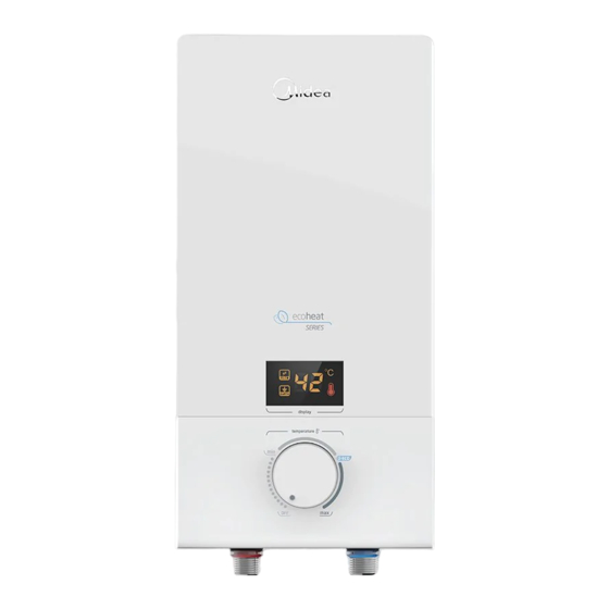
- Page 1 USER’S MANUAL Water Heater ECOHEAT SERIES Rated Voltage: 230V Rated Power: 3800W Frequency: 60Hz Weight: 1.95/2.25kg Dimensions (WxHxD): 200x400x95mm FP-67WTR380WMTM-W1 FP-67WTR380WMTH-B1 version 000 ph.midea.com...
-
Page 2: Table Of Contents
Sincerely, thank you for selecting our electric water heater. Please read this manual carefully before use; correctly grasp the methods for installation and use of this electrical water heater, to make full use of its superior performance. Please do preserve the instruction manual, for future reference. -
Page 3: Caution
1. CAUTION To prevent personal injury, injury to others and property damage, the instructions below must be followed. Incorrect operation due to failure to follow instructions will cause harm or damage. Special Caution This water heater is for household use only and it can be installed indoors where hot water is needed. - Page 4 Ground resistance measurement method: Connect the wire of measuring instrument according to the manual. Please check the diagram ● below. ● Connect E1to the ground wire, and connect E2, P2 to the auxiliary electrode of steel bar in the soil or ground.
-
Page 5: Product Introduction
2. PRODUCT INTRODUCTION 2.1 Technical Performance Parameters Model FP-67WTR380WMTM-W1 FP-67WTR380WMTH-B1 230V~ Rated V oltage Rated Frequency 60 Hz Rated Power 3800W 3800W Rated Current 0~17A 0~17A Dia. Of Wire Cord 4mm² 4mm² Circuit Breaker ≥20A ≥20A R ated Pressure 0 MP a Minimum F low R ate 1.2 Liters/minute Minimum Pressure... - Page 6 2.3 Parts Identi cation Terminal block Main control board Temperature Limiter/ Wire pressing Thermal board cut out Indicator Heating light board elements assembly DC pump Stainless steel circlip Electronic Silicon control Temperature sensor Flow sensor Marker for Marker for wateroutlet water inlet Blue Water inlet...
- Page 7 2.4 Internal Wire Diagram WIRING DIAGRAM FOR FP-67WTR380WMTH-B1 WIRING DIAGRAM FOR FP-67WTR380WMTM-W1 ①:Key board ①:Key board ②:Terminal Block ②:Terminal Block ③:Main Control Board ③:Main Control Board ④:Indicator Light ④:Indicator Light ⑤:Thermal Cut Out ⑤:Thermal Cut Out ⑥:Heating Elements ⑥:Heating Elements ⑦:Temperature Sensor ⑦:Temperature Sensor ⑧:DC Pump...
-
Page 8: Unit Installation
3. UNIT INSTALLATION 3.1 Installation Instruction ① Check the capacity of power circuit (circuit breaker, wires, etc.) ② Power cord installation; ③ Water heater installation; ④ Plumbing connection; ⑤ Power supply connection; ⑥ Water Supply. 3.2 Power Cord Installation Step 1 Step 2 Remove the screws at the bottom of the unit. - Page 9 NOTE The installation position of neutral line (blue), live line (brown/red) and earth line (green/yellow) should be corresponding to the other end of the wiring terminals. 3.3 Water Heater Installation ① Determine installation position of the unit according to length of power cord / position of circuit breaker (Distance between bottom and floor should be ≥1.6m).
- Page 10 Water ow adjusting valve with lter (Fig.2) Cold water inlet NOTE Water flow adjusting valve with filter must be used when installing the unit. Blue marker stands for water inlet, red marker stands for water outlet. Do not apply excessive torque/force to avoid damaging the water heater.
-
Page 11: Usage
4. USAGE 4.1 Operating the unit Switch on the power supply and the LED will light up. If the heater is not working, the light in both the icons will turn o after 15 seconds. Rotate the knob clockwise to switch on the unit and the will display the set temperature. -
Page 12: Maintenance
5. MAINTENANCE This electric water heater should be installed in a place without direct sunshine or where rainwater will not hit the unit. Please cut off power supply if the unit will not be used for a long period of time. Please run the water for about 10 seconds to drain away the impurities in the pipe before connecting the water source to the electric water heater, to avoid clogging. - Page 13 A quality product of Customer Care www.midea.com.ph Email: customercare@midea.com.ph For more information, please visit our website Toll free: 1-800-10-863-5522 Landline: (02) 863-55-22 Viber/SMS: (0917) 863-5522 Monday - Sunday / 8:00am - 8:00pm...
Need help?
Do you have a question about the ECOHEAT Series and is the answer not in the manual?
Questions and answers