
Related Manuals for Rice Lake MSI TranSend Series


Summary of Contents for Rice Lake MSI TranSend Series
- Page 1 MSI TranSend Series Single Channel and Four Channel Installation Manual PN 167375 Rev C...
-
Page 3: Table Of Contents
Course descriptions and dates can be viewed at www.ricelake.com/training or obtained by calling 715-234-9171 and asking for the training department. © Rice Lake Weighing Systems. All rights reserved. Printed in the United States of America. Specifications subject to change without notice. - Page 4 Rice Lake continually offers web-based video training on a growing selection of product-related topics at no cost. Visit www.ricelake.com/webinars MSI TranSend Series...
-
Page 5: Introduction
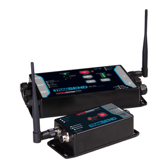
This manual provides the details for TranSend 7000 and TranSend 7001 installation, configuration and calibration. For questions or comments please contact Measurement Systems International at 1-800-874-4320. Manuals can be viewed or downloaded from the Rice Lake Weighing Systems website at www.ricelake.com Four - Single Channel TranSend Transmitters... -
Page 6: Overview
Failure to heed may result in serious injury of death. DO NOT remove or obscure warning labels. There are no user serviceable parts within the TranSend units. Any repairs are to be performed by qualified service personnel only. MSI TranSend Series... -
Page 7: Transend Models Available
1.3 TranSend Models Available Part No DESCRIPTION TRANSMITTERS 5-6 VDC Power Input 160330 Single-channel transmitter, no relays. RF 802.15.4, 2.4 GHz, TranSend 7001 LC 159207 Four-channel transmitter, no relays. RF 802.15.4, 2.4 GHz, TranSend 7000 LC 161949 Four-channel transmitter, includes three coil relays. RF 802.15.4, 2.4 GHz, TranSend 7000 LC 7-36 VDC Power Input 160329 Single-channel transmitter, no relays. -
Page 8: Options
Load cell connector, TranSend. Field wireable, 6-8 mm straight. For use with single channel transmitters 162186 Load cell connector, TranSend. Field wireable, 4-6 mm right angle. For use with single channel transmitters 162187 Load cell connector, TranSend. Field wireable, 6-8 mm right angle. For use with single channel transmitters MSI TranSend Series... -
Page 9: Transend 7000 Front Panel
1.5 TranSend 7000 Front Panel Serial Wi-Fi 802.11 Port 802.15.4 FHSS Set Point Set Point Power Output Input Figure 1-3. TranSend 7000 Front Panel Item No. Description Power In Connection – Located on the side of the unit. Setpoint 1-3 Connections – Located on the side of the unit. Type of power source –... -
Page 10: Transend 7001 Front Panel
1.6 TranSend 7001 Front Panel Measurement Systems WiFi 802.11 International A RICE LAKE WEIGHING SYSTEMS COMPANY 802.15.4 Power In FHSS 85~265 VAC 47~63 Hz Blink Rate 7~36 VDC 1/s = Power OK Load Cell In 2/s = Low EXT BATTERY... -
Page 11: Installation
Immediately after unpacking, visually inspect the contents to ensure all components are included (refer to the packing list) and undamaged. If any parts were damaged in shipment, notify Rice Lake Weighing Systems, MSI Division, and the shipper immediately. Mounting the Enclosure The TranSends can be mounted either vertically or horizontally to a flat surface. - Page 12 8.54" 217 mm 8.09" 205.5 mm 3.97" 100.8 mm 4.70" 3.47" 119.5 mm 88.3 mm 0.25" 6.3 mm 0.17" 4.3 mm 1.57" 40 mm Figure 2-2. Mounting Dimensions – TranSend 7000 MSI TranSend Series...
-
Page 13: Cable Connections
Cable Connections 2.3.1 Connect Transmitter Using the optional pre-wired cable (see Table 2-1) or the field wire-able connector (see Figure 2-3), connect a TranSend 7001 transmitter to the load cell or j-box; eliminating the need for a homerun cable. For TranSend 7000 devices, feed standard load cell cable through the cord grip and wire to the terminal strip according to Figure 2-4. -
Page 14: Connect Receiver
Pwr Adapter, 18W 6VDC Wall Mount. Universal Input 90- 6V Wall Cube for 5-6V TranSend 7000 & 7001, 264VAC. 2.1mm Coax Power Plug. Contains blades for 160110 Int'l mains. International Plugs US, UK, Europe, Aus, China 7-36VDC AC Input Table 2-2. Power Connection Options MSI TranSend Series... -
Page 15: Network Connections
2.4 Network Connections When connecting to a remote device for a network setting, transmitting and receiving units must be set to ensure network and channel settings match. The ScaleCore ID must be unique to each unit. See Section 3.1 on page 14. 2.5 Analog Output Connection 50.0 mm [1.97"] 7.0 mm [0.28"]... -
Page 16: Relays
With normally closed wiring, the contact is closed and energized when the setpoint is inactive. When the setpoint is tripped, the contact will open and the relay will de-energize. See Section 3.4 on page 22 for programming setpoints. MSI TranSend Series... -
Page 17: Scalecore Configuration Management Program (Sccmp)
ScaleCore Configuration Management Program (ScCMP) ScCMP is a software application for configuration and calibration of a ScaleCore based product from a computer. ScCMP and its operation manual are available for download at www.msiscales.com. 1. Download ScCMP to a computer. 2. Connect the transmitter to a computer using a DTE Serial Cable (PN 150964). 3. -
Page 18: Network Settings
Channel Network match for all networked transmitters and receivers. Figure 3-5. Radio Configuration and Caution Boxes 5. Press to save settings and enable the network. Cycle Power on the devices for new radio settings to take effect. MSI TranSend Series... -
Page 19: Calibration (Transmitters)
Calibration (Transmitters) Calibration can also be done using a MSI-8000 or MSI-8000HD. Section 4.0 on page 28 ScCMP provides an interface for performing the available types of sensor (Load Cell) calibration to ensure the ScaleCore product is accurate. The available methods of calibration are: •... -
Page 20: Calibrate With Sccmp
7. Press close, then screen goes to the main screen. 8. Select the LC/Math Sensors 9. Starting with 0, select the sensor that needs calibration. Select from the lower toolbar. Calibrate Calibrate Figure 3-9. LC/Math Sensor Screen 10. The calibration interface screen is displayed. MSI TranSend Series... -
Page 21: Initial And Re-Calibration
Sensor (Load Cell) Calibration Type Figure 3-10. SCCMP Sensor Calibration Dialog 3.2.3 Initial and Re-Calibration 1. Select the sensor (load cell) to calibrate, see Figure 3-10. 2. Select from the drop down box in the controls interface Initial Calibration/Re-Calibration 3. Press the button. -
Page 22: Cal-Number
3. Select , or located at the bottom of that screen and explained in further Calibrate DAC Manual DAC Edit DAC detail in the following sections. DAC outputs may not be available in all ScaleCore family products. MSI TranSend Series... -
Page 23: Calibrate Dac
3.3.1 Calibrate DAC The DAC output is physically hardwired to the channel 4 output connectors on the 7000mV receiver. The channel 1-3 connectors cannot be used to wire the output of the DAC to the indicator that is being used for the output. -
Page 24: Manual Dac
PEAK_NOF Peak weight, first value, only is transmitted ADC_COUNT ADC_COUNT_NOF Development setting only CUR_MODE CUR_MODE_NOF Development setting only, nothing to do with 4-20mA operation TTL COUNT Development setting only Table 3-1. Sensor Value Type Pull Down Menu MSI TranSend Series... - Page 25 Only two Settings are used for 99.9% of applications: • – used in most applications, transmits filtered and allows functions such as Gross Gross Weight Tare Zero the indicator, PC or PLC. Filter level is set under sensor configuration on sensor page. •...
-
Page 26: Setpoints
Setpoints are not intended for batching sequences. Setpoints are free-running setpoints and are intended to be used as interlocks. For more advanced setpoint operation, please consult the indicator’s or PLC’s operation manual. MSI TranSend Series... -
Page 27: Sensors
Sensors The advanced sensor view provides a list of all sensor types and their associated configuration. Figure 3-14. Configuration View - Sensors 3.5.1 Parameters Parameter Description Sensor ID index for every type of sensor. Typical range 0 to 15”. Enabled Enable or Disable the sensor. -
Page 28: Controls
The LC/Math Sensor data view shows weight including ADC count, calibrated weight value with indicators (motion, CoZ) and total/statistics data. Figure 3-15. Data View – LC/Math ADC, total and statistics may not be updated if the monitor is not enabled from the Edit menu. MSI TranSend Series... - Page 29 Parameter Description Sensor ID Sensor index. Typical range 0 to 4 for load and math sensors. Status Current status of the sensor. This will indicate under load, overload, under range, over range, disabled, and other sensor status messages which include: LC_RUN_MODE_ENABLED LC_RUN_MODE_IN_CAL LC_RUN_MODE_NORMAL_ACTIVE...
-
Page 30: Print Setup/Serial Output
Unit, always two Characters. kg, lb, T=Metric Ton, TN = English Ton It is current unit of a specified sensor. If sensor number is not specified before U, default sensor number is 0. Same as U but only the first char. Table 3-7. Dependant Specifiers MSI TranSend Series... - Page 31 12345 LB GR Rice Lake Protocol The following protocol is for use with Rice Lake Weighing Systems indicators s P R 7 S0 T7 A u m t r n Line Feed...
-
Page 32: Calibration With Msi-8000 And 8000Hd
2. Insert a small non-conductive tool into the hole far enough to press the switch. is displayed. Caution should be used when pressing the configuration switch to avoid damage to the switch and other Important board components. MSI TranSend Series... -
Page 33: Initial Calibration
MSI-8000 To calibrate the MSI-8000 indicator, place it into the calibration mode. The blue gasket/shock absorber is transparent for clarity. Calibration Switch Remove Screws Figure 4-2. Press Configuration Switch – MSI-8000 1. Push blue gasket/shock absorber away from the screws and remove the screws. 2. -
Page 34: Routine Calibration
This number will be required when calibrating with , see Section 4.1.4. 14.Press to exit calibration. displays momentarily, then the MSI-8000 or 8000HD is returned to ZERO normal weighing mode. 15.Repeat this procedure to calibrate all load cells connected to the MSI-8000 or 8000HD. MSI TranSend Series... -
Page 35: C-Cal Calibration
4.1.4 C-Cal Calibration When adequate test weights are not available, the scale can be calibrated using a cal number calibration which is referred to as C-Cal. To use C-Cal, a factory generated C-Cal number must be known. MSI supplies replacement load cells with the C-Cal value stamped on the serial number label. -
Page 36: Standard Settings
will display. Pressing resets all display settings to the original factory settings. Important Press the to cancel reset and return to the previous menu. POWER 4. Proceed with the Initial Calibration, Section 4.1.2. MSI TranSend Series... -
Page 37: Appendix
Appendix 5.1 Antenna Options To meet FCC licensing rules, only antennas supplied or recommended by MSI should be used. Antenna placement is critical for problem free use of the system. • Select a relatively clear transmission path between the devices. Radio signals travel primarily by line of sight (LOS), obstructions between stations may degrade the system performance. - Page 38 The patch antenna is for applications where the standard antenna is vulnerable to physical abuse or outdoor applications. The patch antenna is mildly directional which requires more care in placement for long range applications. Patch Antennas are available by special order. Please contact MSI for details. MSI TranSend Series...
-
Page 39: Specifications
5.2 Specifications Accuracy: ±0.05% of applied load Resolution: Up to 10,000 d available Enclosure: NEMA 4, IP66 (excludes universal AC wall cube model) aluminum, black powder coated Weight: 1.7 lb (0.75 kg) Functions: POWER, ZERO, UP/DOWN keys (scrolls through channels) Displayable Units: Pounds, Kilograms, Tons (US Short), Metric Tons, kiloNewtons LED Annunciators:... - Page 40 MSI TranSend Series...
- Page 42 Specifications subject to change without notice. Rice Lake Weighing Systems is an ISO 9001 registered company. 230 W. Coleman St. • Rice Lake, WI 54868 • USA U.S. 800-472-6703 • Canada/Mexico 800-321-6703 • International 715-234-9171 • Europe +31 (0)26 472 1319 www.ricelake.com www.ricelake.mx www.ricelake.eu www.ricelake.co.in...
Need help?
Do you have a question about the MSI TranSend Series and is the answer not in the manual?
Questions and answers