
Subscribe to Our Youtube Channel
Related Manuals for AURES JAZZ-BASE151 Series


Summary of Contents for AURES JAZZ-BASE151 Series
- Page 1 USER'S MANUAL JAZZ-BASE151/JAZZ-KIOSK-BASE l ART-04XXX JAZZ-BASE151-BLACK / JAZZ-BASE151-WHITE JAZZ-KIOSK-BASE151-BLACK/JAZZ-KIOSK-BASE151-WHITE Rev.B Mar20...
- Page 2 FCC Notice FCC Statement This equipment has been tested and found to comply with the limits for a Class A digital device, pursuant to part 15 of the FCC Rules. These limits are designed to provide reasonable protection against harmful interference when the equipment is operated in a commercial environment.
- Page 3 This label is applied to various products to indicate that the product is not to be thrown away, but rather reclaimed upon end of life per this Directive. Safety IMPORTANT SAFETY INSTRUCTIONS To disconnect the machine from the electrical Power Supply, turn off the power switch and remove the power cable plug from the wall socket.
-
Page 4: Table Of Contents
Table of Contents Package Overview ....................2 Product Overview ....................3 Specification ......................4 How to install the Processor Module ..............6 How to Access Power and USB-C Monitor Cables ..........7 How to install the WIFI Dongle ................8 Attaching the 2nd Display .................. -
Page 5: Package Overview
Package Overview JAZZ-BASE151 DC Power Supply Power Cord JAZZ-KIOSK-BASE151(w/o stand) EMV Reader 2nd Display RJ-50 to DB-9M Cable x 2 (Optional) (Optional) iButton Reader User Manual (Optional) (Optional) -
Page 6: Product Overview
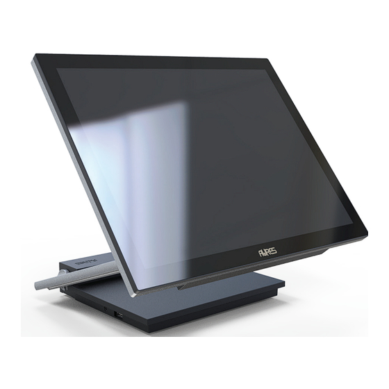
Product Overview JAZZ-BASE151 is an 15 inch touch display module designed for point of sale applications. • Front View (stand is option) • Bottom View... -
Page 7: Specification
Specification Model Name JAZZ-BASE151/JAZZ-KIOSK-BASE151 CPU support Intel® Intel® Core™ Intel® Core™ BayTrail Skylake Kabylake Processor J1900 i3-6100U Processor i5-7300U Processor (2M Cache, (3M Cache, (3M Cache, up to 2.42 GHz) 2.30 GHz) up to 3.50 GHz) System Memory DDR3L DDR4 1 x SO-DIMM 4GB Std Max 8GB 4GB Std Max 16GB... - Page 8 Power Power Adapter External 19V / 3.42A 65Watt Adapter Certifications FCC Class A / CE Environment Operating 0-40°C Temperature Storage -20°C-60°C Temperature Humidity 5%-80% non-condensing Dimension LCD 0 degree : (W x D x H) 517.44 x 54.08 x 313.31mm Weight 5.4kg / 7.1kg(JAZZ-BASE151) (N.W./G.W.)
-
Page 9: How To Install The Processor Module
How to install the Processor Module 1. Lay the LCD flat on a clean even surface. 2. Move the stand into position as shown in the step 2 diagram. 3. Remove the back cover as seen in the step 3 diagram. 4. -
Page 10: How To Access Power And Usb-C Monitor Cables
How to Access Power and USB-C Monitor Cables 1. Lay the LCD flat on a clear even surface. 2. Remove the 4 screws to remove the stand bottom cover as seen in the step 1 diagram. 3. Connect the USB-C and power cable to the appropriate connectors as seen in the step 2 diagram. -
Page 11: How To Install The Wifi Dongle
How to install the WIFI Dongle 1. Lay the LCD flat on an even surface. 2. Remove the MB cover as seen in the step 2 diagram. 3. Insert the WIFI Dongle to the appropriate as seen in the step 3&4 diagram. 4. -
Page 12: Attaching The 2Nd Display
Attaching the 2nd display Before attaching the 2nd display to your monitor, please make sure your monitor and computer are turned off. Remove the thumb screw from a. Rotate 2nd display and move the bracket into position. 2nd display. b. insert the thumb screw. Remove the display arm cover Remove the rear cover cap from from 2nd display. -
Page 13: Attaching The Msr
Attaching the MSR Before attaching the MSR to your monitor, please make sure your monitor and computer are turned off. Remove the rear cover cap. Insert the MSR to the appropriate as seen in the diagram. -
Page 14: Attaching The Emv Reader
Attaching the EMV Reader Before attaching the EMV Reader to your monitor, please make sure your monitor and computer are turned off. Remove the rear cover cap. Insert the EMV Reader to the appropriate as seen in the diagram. -
Page 15: Attaching The Ibutton Reader
Attaching the iButton Reader Before attaching the iButton Reader to your monitor, please make sure your monitor and computer are turned off. Remove the rear cover cap. Insert the iButton Reader to the appropriate as seen in the diagram. -
Page 16: Removing The 2Nd Display
Remove the 2nd display Before removing the 2nd display from your monitor, please make sure your monitor and computer are turned off. Uninstall the display arm cover Remove the 4 screws in 2nd from 2nd display. display. Attached the rear cover cap to Move the 2nd display from monitor. -
Page 17: Removing The Msr
Remove the MSR Before removing the MSR to your monitor, please make sure your monitor and computer are turned off. Remove rear cover cap from monitor. a. Release the hook by a slim needle. b. Remove the MSR as seen in diagram. Attached the rear cover cap. -
Page 18: Removing The Emv Reader
Remove the EMV Reader Before removing the EMV Reader to your monitor, please make sure your monitor and computer are turned off. Remove rear cover cap from monitor. a. Release the hook by a slim needle. b. Remove EMV as seen in diagram. Attached the rear cover cap. -
Page 19: Removing The Ibutton Reader
Remove the iButton Reader Before removng the iButton Reader to your monitor, please make sure your monitor and computer are turned off. Remove rear cover cap from monitor. a. Release the hook by a slim needle. b. Remove iButton as seen in diagram. Attahced the rear cover cap. -
Page 20: I/O Connection
I/O connection USB-C USB-C USB 3.0 USB 3.0 USB 3.0 USB 3.0 COM 2 COM 1 DC 19V... -
Page 21: Product Dimensions
Product Dimensions 340.0 201.0... -
Page 22: Appendix A: Driver Install
Appendix A: Driver Installation To download the most recent drivers and utilities, and obtain advice regarding the installation of your equipment, please visit the AURES Technical Support Website www.aures-support.com...
Need help?
Do you have a question about the JAZZ-BASE151 Series and is the answer not in the manual?
Questions and answers