Table of Contents
Advertisement
Advertisement
Table of Contents

Related Manuals for AURES NINO II


Summary of Contents for AURES NINO II
- Page 1 User Manual Version 1.0 April 2015 NINÔ II...
- Page 2 Copyright 2015 All Rights Reserved Manual Version 1.0 The information contained in this document is subject to change without notice. We make no warranty of any kind with regard to this material, including, but not limited to, the implied warranties of merchantability and fitness for a particular purpose.
-
Page 3: Important Safety Instructions
Safety IMPORTANT SAFETY INSTRUCTIONS To disconnect the machine from the electrical Power Supply, turn off the power switch and remove the power cord plug from the wall socket. The wall socket must be easily accessible and in close proximity to the machine. Read these instructions carefully. -
Page 4: Legislation And Weee Symbol
CAUTION ON LITHIUM BATTERIES There is a danger of explosion if the battery is replaced incorrectly. Replace only with the same or equivalent type recommended by the manufacturer. Discard used batteries according to the manufacturer’s instructions. Battery Caution Risk of explosion if battery is replaced by an incorrectly type. Dispose of used battery according to the local disposal instructions. -
Page 5: Revision History
Revision History Revision Date Description V1.0 April, 2015 Release... -
Page 6: Table Of Contents
Table of Contents 1 Item Checklist ..........1 1-1 Standard Items ................1 1-2 Optional Items ................2 2 System View ........... 3 2-1 Front View & Rear View ..............3 2-2 Side View ..................4 2-3 Bottom View ..................4 2-4 ... -
Page 7: Item Checklist
Item Checklist Standard Items a. System b. Power adapter (65W) c. Power cable d. RJ45-DB9 cable (x4) e. Manual CD... -
Page 8: Optional Items
Optional Items a. MSR module b. iButton module c. Addimat reader d. Customer display ( Graphic LCM ) display Wall Mount kit... -
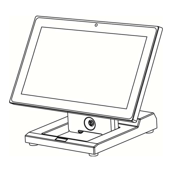
Page 9: System View
System View Front View & Rear View Number Description LED indicator Touch screen Thumb screw for the cable cover Ventilation hole HDD door VFD/2 display dummy cover MSR/iButton/Addimat key module dummy cover Swing arm base... -
Page 10: Side View
Side View Fold down the swing arm base Bottom View Number Description Rubber foot Power adapter (with holder bracket) IO ports... -
Page 11: Dimension & View Angle
Dimension & View Angle... -
Page 13: I/O View
I/O View Number Description Line out Display port Mic in Power button 19V DC in COM1~3 (from right to left) USB x 4 (USB2.0) Cash drawer USB x 2 (USB3.0) -
Page 14: System Assembly & Disassembly
System Assembly & Disassembly Install the Power Adapter The system is equipped with a 65W power adapter. Please follow the steps below to install the power adapter. The swing arm base is designed to allow for clean cable management. There is a cable channel through the swing arm base, which has a quick access cover. -
Page 15: Replace The Hdd
Replace the HDD Remove the HDD/SSD cover retaining a screw and sliding the drive out. Unclip the HDD cover from the drive as shown in the picture. Replace the SSD Card Remove the HDD/SSD cover retaining a screw and sliding the drive out. -
Page 16: Peripherals Installation
Peripherals Installation Install the MSR Module MSR is installed on the right side of the system. Please make sure the unit is powered down before starting. Remove the dummy cover first. Connect the MSR cable (x1) to the connector on the system side. Insert the MSR module in place and fasten the screws (x2) on the back to secure the module. -
Page 17: Install The Ibutton Module
Install the iButton Module iButton is installed on the left side of the system. Please make sure the unit is powered down before starting. Remove the dummy cover first and then unfasten the screws (x2). Connect the iButton cable to the connector on the system side. -
Page 18: Install The Addimat Key Reader
Install the Addimat Key Reader Addimat key reader is an option instead of iButton module. It is also installed on the left side of the system. Please make sure the unit is powered down before starting. Remove the dummy cover first and then unfasten the screws (x2). -
Page 19: Install The Customer Display (Graphic Lcm)
Install the Customer Display (Graphic LCM) Remove the dummy cover first. After the dummy cover is removed, plug the 8-pin LCM cable into the CN8 / LCM connector on the system board. Fasten the screws (x2) to secure the LCM display to the system. The Customer Display is directly connected to COM6 and uses the following communication parameters: 9600, N, 8, 1. - Page 20 Install the 2 Display Loosen the thumb screw (x1) of the cable cover first. Attach the 2 display on to the swing arm base and fasten the screws(x2) to fix the 2 display. Lay down system to access the bottom of the base. Loosen the screws (x2) of the holder bracket to release the power adapter.
- Page 21 After the power adapter is released, a nameplate is attached to the edge of the swing arm base. Remove this nameplate as shown in the picture. After the nameplate is removed, a small hole is revealed. Thread the cable of 2 display through the hole and then route the cable as shown in the picture.
- Page 22 Finally put the cable cover back and fasten the thumb screw.
-
Page 23: How To Activate The 2 Nd Display Under Windows
4-5-1 How to activate the 2 display Under Windows Make sure to connect the 2 display cable and begin the installation after your system has booted. The Setup program requires about one minute for the installation. If you turn the ... - Page 24 Click the Appearance and Personalization to enter the menu. Select Display from the menu and the display properties windows appears.
- Page 25 Arrange the monitors displayed in the order they are actually used. Remember to click Apply before exiting the menu. Click Keep Changes and then click OK to save the setting.
-
Page 26: Install The Wall Mount Kit
Install the Wall Mount Kit The wall mount come with the following parts: 8mm screw x 8 Mounting Clip x 4 4 mm screw x 1 Mounting bracket First attach the four mounting clips using the 3 mm screws as shown in the picture. - Page 27 Next step is to route any cables you need to go to the system as required. A space is provided just by the power supply for the cable to exit cleanly, assuming they are routed via the swing arm cable channel as in a normal install.
- Page 28 Some possible viewing angles using the wall mount bracket.
-
Page 29: Install The Cash Drawer
Install the Cash Drawer You can install a cash drawer through the cash drawer port. Please verify the pin assignment before installation. Cash Drawer Pin Assignment Signal Cash drawer 2 In Cash drawer 1 Out Cash drawer 1 In 12V / 19V (OR 24v) Cash drawer 2 Out Cash Drawer Controller Register The Cash Drawer Controller use one I/O addresses to control the Cash Drawer. - Page 30 Bit 7: Cash Drawer 2 pin output control Bit 6: Reserved Bit 5: Cash Drawer 2 pin input control Bit 4: Cash Drawer 1 pin output control. = 1: Opening the Cash Drawer = 0: Allow close the Cash Drawer Bit 3: Cash Drawer 1 pin input control.
-
Page 31: Specification
Specification Model Name NINÔ II Motherboard Intel Bay Trail SoC CPU support Celeron J1900 2.0GHz, L2 2MB, TDP 10W (default) Chipset System memory DDR3L S.O. DIMM x1, FSB 1066/1333hz, default 2G, max. 8G Graphic memory Intel HD Graphic DX11.1 LAN controller Realtek RTL8111E-VL-CG 10/100/1000 baseT LAN Audio controller Realtek ALC662VDO-GR... - Page 32 Model Name NINÔ II Motherboard Cash drawer 1 x RJ 11 (12V/24V cash drawer ), jumper setting, default 24V Display port Power button Audio jack 1 x Line-out / 1x Mic-in Speaker speaker 1 x 2W Power Power adapter Ext. 65W/19V Peripherals MSR module MSR 3 track (USB, secured head )
-
Page 33: Configuration
Configuration D36 Motherboard Layout... -
Page 34: Connectors & Functions
Connectors & Functions Connector Function Front I/O board Inverter connector LVDS connector System FAN connector LPT port connector Speaker & MIC connector 40pin external connector CN10 HDD LED connector CN11 Power LED connector CN12 SATA power connector CN13/14 USB port (internal) CN15 PS2 keyboard connector CN16... -
Page 35: Jumper Settings
Jumper Settings Inverter Selection Function (1-2) (3-4) ▲LED CCFL Cash Drawer Power Setting Function (1-2) (3-4) ▲+19V +12V LCD ID Setting Panel LVDS Output Resolution (1-2) (3-4) (5-6) (7-8) (9-10) Number Bits Channel Interface 800 x 600 Single LVDS Panel 800 x 600 Single LVDS Panel... - Page 36 1024 x 600 Single LVDS Panel 1280 x 1024 Dual LVDS Panel 1440 x 900 Dual LVDS Panel 1920 x 1080 Dual LVDS Panel COM1/COM2/COM3 Power Setting COM1, COM2 and COM3 can be set to provide power to your serial device. The voltage can be set to +5V or 12V in the BIOS.
- Page 37 To enable the power, select COM1 , COM2 or COM3 Power setting and press <Enter>. Select Power and press <Enter>. Save the change by pressing F10.
-
Page 38: Appendix: Driver Installation
Appendix: Driver Installation To download the most recent drivers and utilities, and obtain advice regarding the installation of your equipment, please visit the AURES Technical Support Website: www.aures-support.fr (French) www.aures-support.fr/UK (English) www.aures-support.fr/GE (German)
Need help?
Do you have a question about the NINO II and is the answer not in the manual?
Questions and answers