Table of Contents
Advertisement
Advertisement
Table of Contents

Related Manuals for AURES TMC 7200


Summary of Contents for AURES TMC 7200
- Page 1 Version 1.1 Nov. 2020...
- Page 2 TMC7200 ® 7" Integrated Handy POS with Intel ® Atom Z8550 Quad Core™ CPU Copyright 2020 All Right Reserved Manual Version 1.1 TRADEMARK All trademarks and registered trademarks mentioned herein are the property of their respective owners. You may not reproduce or transmit in any form or by any means, electronic, or mechanical, including photocopying and recording.
- Page 3 FCC NOTICE This device complies with part 15 of the FCC Rules. Operation is subject to the following two conditions: (1) This device may not cause harmful interference, and (2) this device must accept any interference received, including interference that may cause undesired operation. NOTE: This equipment has been tested and found to comply with the limits for a Class A digital device, pursuant to part 15 of the FCC Rules.
-
Page 4: Table Of Contents
Contents Introduction ..................1-1 About This Manual ..............1-2 Getting Started ..................2-2 Package List ................2-2 System Overview ............... 2-3 Specifications ................2-12 2.3.1 Tablet ..................2-12 2.3.2 Charging dock ................ 2-13 2.3.3 4-slots Charging dock ............2-13 Software Utilities ................. 3-1 Introduction................. - Page 5 Advanced ................. 4-11 4.4.1 Advanced – Security Configuration ........4-12 4.4.2 Advanced – Chipset Configuration ........4-14 4.4.3 Advanced – USB Configuration ........4-15 Security ..................4-16 Boot ..................4-18 Save & Exit ................4-20...
- Page 6 Revision History The revision history of TMC7200 User Manual is described below: Version No. Revision History Date 08/2020 Initial Release 11/2020 Add 4-slot Charging Dock & Rotatable Hand Strap...
-
Page 7: Introduction
Introduction This chapter provides the introduction for the TMC7200 system as well as the framework of the user manual. The following topic is included: • About This Manual Page: 1-1 TMC7200 SERIES USER MANUAL... -
Page 8: About This Manual
Chapter 1 Introduction About This Manual Thank you for purchasing our TMC7200 system. The TMC7200 provides faster processing speed, greater expandability and can handle more tasks than before. This manual is designed to assist you how to install and set up the whole system. -
Page 9: Getting Started
Getting Started This chapter provides the information for the TMC7200 system. The following topics are included: • Package List • System Diagrams • Specifications • Safety Precautions Page: 2-2 TMC7200 SERIES USER MANUAL... - Page 10 Chapter 2 Getting Started Package List If you discover any of the items listed below are damaged or lost, please contact your local distributor immediately. Tablet: Item Q’ty TMC7200(with battery) Quick Reference Guide Hand Strap Wrist Strap Card reader or MSR (Optional) 2D Scanner (Optional) Retractable leash(Optional) Rotatable Hand Strap(Optional)
-
Page 11: System Overview
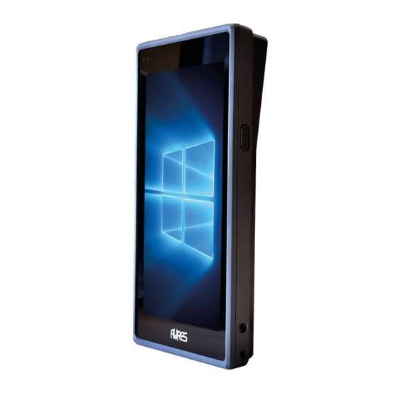
Chapter 2 Getting Started System Overview Unit: mm Tablet Charging dock Tablet 4-slots Charging dock Tablet Hand Strap+ MSR module Page: 2-3 TMC7200 SERIES USER MANUAL... - Page 12 Chapter 2 Getting Started Tablet Rotatable Hand Strap+ MSR module Page: 2-4 TMC7200 SERIES USER MANUAL...
- Page 13 Chapter 2 Getting Started Page: 2-5 TMC7200 SERIES USER MANUAL...
- Page 14 Chapter 2 Getting Started Page: 2-6 TMC7200 SERIES USER MANUAL...
- Page 15 Chapter 2 Getting Started Page: 2-7 TMC7200 SERIES USER MANUAL...
- Page 16 Chapter 2 Getting Started MSR module installation Rotatable Hand Strap installation Page: 2-8 TMC7200 SERIES USER MANUAL...
- Page 17 Chapter 2 Getting Started Page: 2-9 TMC7200 SERIES USER MANUAL...
- Page 18 Chapter 2 Getting Started In addition, if this function is enable you have 2 additional functions : (1) Sleep indicator mode (enable by default) When screen off, keep pressing during 3 seconds enabled L/R-buttons to : (i) activate sleep indicator mode (Tablet LED indicator will blink 3 times in green-yellow-green colors).
- Page 19 Chapter 2 Getting Started when you press the power button). To unlock the shipping mode, you have just to put on plugged charger => Tablet LED indicator will bright in Red during 8 seconds (Battery checking). And after that you can start tablet normally.
-
Page 20: Specifications
Chapter 2 Getting Started Specifications 2.3.1 Tablet Tablet System(TMC7200-7400) ® ® Intel Atom x5-Z8550 Quad Core CPU Supports 1.44GHz up to 2.4GHz Memory LPDDR3 4GB on board Storage eMMC 64GB on board OS support Windows 10 IoT Ent 2019 LTSC (64 bits) Power Requirement DC 12V/2A by by Pogo Pin... -
Page 21: Charging Dock
Chapter 2 Getting Started Micro SD up to 128GB Environment Operating Temp. 0°C~ 35°C (32°F ~ 95°F) Storage Temp. -20°C~ 60°C (-4°F~ 140°F) Operating Humidity 10%~ 90% 2.3.2 Charging dock Charging dock System(TMC7000-Charger) Kensington lock One slot Power supply Adapter Input: 100~240V, 50/60 Hz;... - Page 22 Chapter 2 Getting Started Safety Precautions Before operating this system, read the following information carefully to protect your systems from damages, and extend the life cycle of the system. Check the Line Voltage • The operating voltage for the power supply should be within the range of 100V to 240V AC;...
-
Page 23: Software Utilities
Software Utilities This chapter provides the detailed information that guides users to install driver utilities for the system. The following topics are included: • Installing Intel ® Chipset Software Installation Utility • Installing Audio Realtek Software Installation Utility • Installing G-Sensor Software Installation Utility •... - Page 24 Chapter 3 Software Utilities Introduction TMC7200 Driver Utilities have been stored in the Integrated Pad system: File Path: C:\TMC7200_v1.0 Win10 Purpose 64bit Intel® Chipset Device Software installer C:\TMC7200_v1.0\DRIVER\ (Audio & BM&Camera & DPTF & GFX & Platform\1_Main Chip GPIO & GPIO & I2C & MBI & PMIC & \Win10-64Bit Sensor &...
-
Page 25: Introduction
Chapter 3 Software Utilities ® Installing Intel Chipset Software Installation Utility Introduction ® The Intel Chipset Software Installation Utility installs the Windows *.INF files to the target system. These files outline to the operating system how to configure the Intel chipset components in order to ensure that the following functions work properly: Core PCI and ISAPNP Services... - Page 26 Chapter 3 Software Utilities After the Chipset driver is installed, the following driver utilities will also be installed at the same time: Audio driver utility • BM driver utility • Camera driver utility • DPTF driver utility • GFX driver utility •...
-
Page 27: Installing Audio Realtek Software Installation Utility
Chapter 3 Software Utilities Installing Audio Realtek Software Installation Utility After the default Audio driver utility has been installed in the procedure above, it will not function until you have installed Realtek ALC5640-VB-CG driver utilities. Please follow the steps below: Enter the C:\TMC7200_v1.0 >... - Page 28 Chapter 3 Software Utilities Page: 3-6 TMC7200 SERIES USER MANUAL...
- Page 29 Chapter 3 Software Utilities From Realtek I2S Audio Codec Properties window, click Update Driver… from the Driver tab to start updating the audio driver software for TMC7200. Click Browse my computer for driver software item. Page: 3-7 TMC7200 SERIES USER MANUAL...
- Page 30 Chapter 3 Software Utilities Click Let me pick from a list of device drivers on my computer. Click Have Disk…. Page: 3-8 TMC7200 SERIES USER MANUAL...
- Page 31 Chapter 3 Software Utilities Click Browse... button to browse for the file directory where the Realtek I2S Audio Codec installation driver is located. Select C:\TMC7200_v1.0 > DRIVER > Platform > 2_Audio > Win10-64Bit > RTK_6_2_9600_4239_WHQL> x86, select rtii2sac.inf file and click Open to open the file. Page: 3-9 TMC7200 SERIES USER MANUAL...
- Page 32 Chapter 3 Software Utilities Click OK. Click Next to continue the installation. Page: 3-10 TMC7200 SERIES USER MANUAL...
- Page 33 Chapter 3 Software Utilities Windows has finished installing Realtek I2S Audio Codec driver software. Click Close to complete. Go to Realtek I2S Audio Codec Properties window and select Driver tab, and you will see the Realtek audio driver utility has been updated. Click Close to exit. Page: 3-11 TMC7200 SERIES USER MANUAL...
- Page 34 Chapter 3 Software Utilities Once the installation is completed, restart TMC7200 for the changes to take effects, and the audio function can start to work normally. Page: 3-12 TMC7200 SERIES USER MANUAL...
-
Page 35: Installing G-Sensor Software Installation Utility
Chapter 3 Software Utilities Installing G-Sensor Software Installation Utility The G-Sensor driver utility provided allows users to turn the touch screen horizontally or vertically. Please follow the steps below to install G-Sensor driver utilities: Enter the C:\TMC7200_v1.0 >DRIVER > Platform > 3_G-sensor >... - Page 36 Chapter 3 Software Utilities Page: 3-14 TMC7200 SERIES USER MANUAL...
- Page 37 Chapter 3 Software Utilities From STMicroelectronics 3-Axis Digital Accelerometer Properties window, click Update Driver… from the Driver tab to start install the G-sensor driver software for TMC7200. Click Browse my computer for driver software item. Page: 3-15 TMC7200 SERIES USER MANUAL...
- Page 38 Chapter 3 Software Utilities Click Let me pick from a list of device drivers on my computer. Click Have Disk… button. Page: 3-16 TMC7200 SERIES USER MANUAL...
- Page 39 Chapter 3 Software Utilities Click Browse… button to browse for the file directory where the G-sensor installation driver is located. Select C:\TMC7200_v1.0 > DRIVER > Device > G-sensor > Win10-64Bit >2_Accel_SPB_SensorAPI_2.8.1.10(STEP-2) > x86 folder from the Look in drop-down box, and select ST_Accel.inf file.
- Page 40 Chapter 3 Software Utilities Page: 3-18 TMC7200 SERIES USER MANUAL...
- Page 41 Chapter 3 Software Utilities Click OK. Click Next to continue the installation. Page: 3-19 TMC7200 SERIES USER MANUAL...
- Page 42 Chapter 3 Software Utilities Windows has finished installing G-sensor driver software. Click Close to complete. Page: 3-20 TMC7200 SERIES USER MANUAL...
- Page 43 Chapter 3 Software Utilities Go to STMicroelectronics 3-Axis Digital Accelerometer Properties window and select Driver tab, and you will see the STMicroelectronics G-sensor driver utility has been updated. Click Close to exit. Once the installation is completed, restart TMC7200 for the changes to take effects.
-
Page 44: Installing Wifi And Bluetooth Software Installation Utility
Chapter 3 Software Utilities Installing WiFi and Bluetooth Software Installation Utility 4.5.1 Installing Wi-Fi Software Installation Utility Please follow the steps below to install Bluetooth driver utilities: Enter the C:\TMC7200_v1.0 > DRIVER > Platform > 4_Bluetooth > Win10-64Bit > AP6356SDPR\WiFi\x64\ DHD_1.558.53.33_Win10_x64_HLK_driveronly folder.. -
Page 45: Bios Setup
BIOS SETUP This chapter guides users how to configure the basic system configurations via the BIOS Setup Utilities. The information of the system configuration is saved in BIOS NVRAM so that the Setup information is retained when the system is powered off. -
Page 46: Introduction
Chapter 4 BIOS Setup Introduction The board TMC7200 < CherryTrail > uses an Insyde < CherryTrail > uses an Insyde BIOS that is stored in the Serial Peripheral Interface Flash Memory (SPI Flash) and can be updated. The Serial Peripheral Interface Flash Memory (SPI Flash) and can be updated. The SPI Flash contains the BIOS Setup program, Power SPI Flash contains the BIOS Setup program, Power-on Self-Test (POST), the PCI auto-configuration utility, LAN EEPROM information, and Plug and Play... -
Page 47: Accessing Setup Utility
Chapter 4 BIOS Setup The BIOS setup menu allows users to view and modify the BIOS settings for the computer. After the system is powered on, users can access the BIOS setup menu by pressing <Del> or <Esc> immediately while the POST message is running before the operating system is loading. - Page 48 Chapter 4 BIOS Setup Figure 4-3. Front Page Screen Press <Esc> (the one that shares the decimal point at the bottom of the number keypad) to select SCU icon to access the Setup program. In a moment, the main menu of the Insyde Setup Utility will appear on the screen: Page: 4-4 TMC7200 SERIES USER MANUAL...
- Page 49 Chapter 4 BIOS Setup BIOS Setup Menu Initialization Screen You may move the cursor by <↑> and <↓> keys to highlight the individual menu items. As you highlight each item, a brief description of the highlighted selection will appear at the bottom of the screen. The language of the BIOS setup menu interface and help messages are shown in US English.
- Page 50 Chapter 4 BIOS Setup BIOS Setup Description Navigation Key <Esc> Close the sub-menu. Trigger the confirmation to exit BIOS setup menu. Page: 4-6 TMC7200 SERIES USER MANUAL...
-
Page 51: Main
Chapter 4 BIOS Setup Main Menu Path Main The Main menu allows you to view the BIOS Information, change the system date and time, and view the user access privilege level. Use tab to switch between date elements. Use <↑> or <↓> arrow keys to highlight the item and enter the value you want in each item. - Page 52 Chapter 4 BIOS Setup BIOS Setting Options Description/Purpose No changeable MCU Version Displays the MCU version. options No changeable Displays the Serial Number of Serial Number options motherboard Percentage of Battery No changeable Displays battery level. level options System Memory No changeable Displays Memory Speed.
- Page 53 Chapter 4 BIOS Setup BIOS Setting Options Description/Purpose Displays the DODIMM 1 SODIMM 1 No changeable options size. Displays the CPU's stepping CHV SOC No changeable options information. MRC Version No changeable options Displays the MRC Version. Displays the PUNIT FW PUNIT FW No changeable options Version.
- Page 54 Chapter 4 BIOS Setup Main Screen BIOS Setting Options Description/Purpose Displays the Board ID of the Board ID No changeable options SoC. Fab ID No changeable options Displays the Fab ID. - English - Francais Language 中 文 Select the current default 日...
-
Page 55: Advanced
Chapter 4 BIOS Setup Advanced Menu Path Advanced This menu provides advanced configurations for setting Security Configuration and Chipset Configuration. Advanced Menu Screen BIOS Setting Options Description/Purpose Security Sub-Menu Security Configuration. Configuration Chipset Advanced Chipset Configuration Sub-Menu Configuration Options. Page: 4-11 TMC7200 SERIES USER MANUAL... -
Page 56: Advanced - Security Configuration
Chapter 4 BIOS Setup 4.4.1 Advanced – Security Configuration Menu Path Advanced > Security Configuration Security Configuration Screen Page: 4-12 TMC7200 SERIES USER MANUAL... - Page 57 Chapter 4 BIOS Setup BIOS Setting Options Description/Purpose TXE Configuration TXE FW version No changeable options TXE FW Version TXE FW No changeable options TXE FW Capabilities Capabilities TXE FW Features No changeable options TXE FW Features TXE FW OEM Tag No changeable options TXE FW OEM Tag TXE Firmware...
-
Page 58: Advanced - Chipset Configuration
Chapter 4 BIOS Setup 4.4.2 Advanced – Chipset Configuration Menu Path Advanced > Chipset Configuration Security Configuration Screen BIOS Setting Options Description/Purpose Chipset Configuration - Enabled To control the NFC NFC Switch - Disabled function on the O.S. - Enabled To control camera Camera Switch - Disabled... -
Page 59: Advanced - Usb Configuration
Chapter 4 BIOS Setup 4.4.3 Advanced – USB Configuration Menu Path Advanced > USB Configuration Security Configuration Screen BIOS Setting Options Description/Purpose - Enabled Control each of the USB USB Per-Post Control - Disabled ports (0 ~ 9) disabling. - Enabled USB Port #0 Disable USB port #0. -
Page 60: Security
Chapter 4 BIOS Setup Security Menu Path Security From the Security menu, you are allowed to create, change or clear the supervisor password. You will be asked to enter the configured supervisor password before you can access the Setup Utility. By setting a supervisor password, you will prevent other users from changing your BIOS settings. - Page 61 Chapter 4 BIOS Setup BIOS Setting Options Description/Purpose Enable: Enable Storage and Endorsement -No Operation Hierarchy TPM Operation -Disable Disable: Disable Storage -Enable and Endorsement Hierarchy Clear TPM. Removes all -Disabled Clear TPM TPM conttect associated -Enabled with a specific Owner. Displays the Supervisor Supervisor Password No changeable options...
-
Page 62: Boot
Chapter 4 BIOS Setup Boot Menu Path Boot This menu provides control items for system boot configuration such as setting setup prompt timeout, enabling/disabling quick boot, quiet boot, Network Stack and PXE Boot capability, configuring ACPI (Advanced Configuration and Power Management Interface) settings and USB boot. Boot Screen BIOS Setting Options... - Page 63 Chapter 4 BIOS Setup BIOS Setting Options Description/Purpose - Acpi 1.0B - Acpi 3.0 ACPI Selection Select booting to ACPI - Acpi 4.0 - Acpi 5.0 - Enabled Disabled or Enabled booting to USB Boot - Disabled USB boot devices. The number of seconds that the firmware will wait before Timeout...
-
Page 64: Save & Exit
Chapter 4 BIOS Setup Save & Exit Menu Path Exit The Exit allows users to save or discard changed BIOS settings as well as load the optimized defaults for BIOS settings. Exit Screen BIOS Setting Options Description/Purpose Exits and saves the Exit Saving Changes No changeable options changes in NVRAM.
Need help?
Do you have a question about the TMC 7200 and is the answer not in the manual?
Questions and answers