Table of Contents
Advertisement
Quick Links
Advertisement
Table of Contents

Related Manuals for Time Electronics 1030 MicroCal


Summary of Contents for Time Electronics 1030 MicroCal
- Page 1 User Manual 1030 MicroCal Voltage and Current Source Version 1.2 02-23 Time Electronics Ltd Unit 5, TON Business Park, 2-8 Morley Road, Tonbridge, Kent, TN9 1RA, United Kingdom. T: +44 (0) 1732 355993 | F: +44 (0) 1732 350198 mail@timeelectronics.co.uk | www.timeelectronics.com...
- Page 2 All rights reserved. Nothing from this manual may be multiplied, or made public in any form or manner, either electronically or hard copy, without prior written consent from Time Electronics Ltd. This also applies to any schematics, drawings and diagrams contained herein.
-
Page 3: Table Of Contents
Time Electronics 1030 MicroCal Voltage and Current Source User Manual Contents Introduction ............................ 2 Specifications ..........................4 Controls ............................5 Description of Controls .......................... 6 Operation ............................7 Voltage Ranges ............................. 7 Output Voltages above 1 V ........................8 Current Ranges ............................. 8 Output Resistance .......................... -
Page 4: Introduction
User Manual Introduction The 1030 MicroCal is a portable voltage and current calibrator for general purpose signal injection. It is suitable for voltage and current loop signal simulation as well as thermocouple simulation. Being both cost-effective and simple operation, it is a popular instrument used in various applications across industries. - Page 5 Time Electronics 1030 MicroCal Voltage and Current Source User Manual Features 10 mV, 100 mV, 1 V ranges • 10 mA, 100 mA ranges • • Accuracy 0.1 % Linearity 0.15 % • Up to 8 V output (using 1 kΩ resistor) •...
-
Page 6: Specifications
Time Electronics 1030 MicroCal Voltage and Current Source User Manual Specifications Voltage Ranges: 0 to 1 V (1 mV resolution). 0 to 100 mV (100 µV resolution). 0 to 10 mV (10 µV resolution). 8 Volts (10 mV resolution) using external precision 1KΩ resistor supplied. -
Page 7: Controls
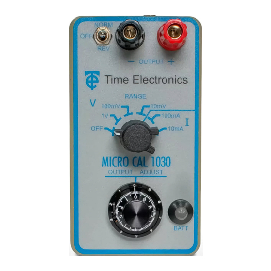
Time Electronics 1030 MicroCal Voltage and Current Source User Manual Controls Recharge Socket (on top) Output Terminals For recharging NiMH battery (if fitted) Output polarity switch Selects Normal/Off/Reverse 6 position rotary switch Selects range and turns instrument on. 10 turn potentiometer Selects required output. -
Page 8: Description Of Controls
Time Electronics 1030 MicroCal Voltage and Current Source User Manual Description of Controls Output Terminals Output Voltage and Current is available on two front panel terminals which are suitable for either wire compression or 4mm standard plug insertion. Polarity Switch Normal or reverse polarity is selected by a toggle switch. -
Page 9: Operation
Time Electronics 1030 MicroCal Voltage and Current Source User Manual Operation Voltage Ranges Suggested operation procedure is as follows: Select Off position on output switch. Turn on and select required range. Check battery level indicator for high enough reading, or when fitted, LED is Illuminated green (see Battery Replacement Section 6). -
Page 10: Output Voltages Above 1 V
Time Electronics 1030 MicroCal Voltage and Current Source User Manual Output Voltages above 1 V To use the 8V range, connect the supplied 1 kΩ resistor across the output terminals, and switch to the 10mA range. The 1030 will act as a voltage source, the output being adjusted with the 10-turn dial, with a scale of 1 volt per turn up to a maximum of about 8 volts with a good battery. -
Page 11: Applications
Time Electronics 1030 MicroCal Voltage and Current Source User Manual Applications Four Terminal Resistance Measurements Accurate measurements of low ohm values, such as P.R.T, can be performed by using the 1030 as a current source and measuring the voltage across the LOAD with a DVM. -
Page 12: Thermocouple Simulation
Time Electronics 1030 MicroCal Voltage and Current Source User Manual Thermocouple Simulation The 10mV range of the 1030 is ideal for simulation of all types of thermocouple. Just find the voltage required from the British Standard tables, (common values given below), and set up on the 1030’s dial. -
Page 13: Battery Replacement And Recharging
Time Electronics 1030 MicroCal Voltage and Current Source User Manual Battery Replacement and Recharging The battery capacity for rechargeable types is approx. 150 mAH, whereas non rechargeable types are approx. 500 mAH. The 1030 circuitry takes approximately 8 mA and will operate over a DC supply voltage range of 7-12 volts. -
Page 14: Calibration
Time Electronics 1030 MicroCal Voltage and Current Source User Manual Calibration The instrument is calibrated before it leaves the factory and the calibration controls will not normally require adjustment. If re-adjustment is considered necessary, and the trimmer range is found to be insufficient for recalibration, there is a fault with the instrument. -
Page 15: Module And Trimmer Location
Time Electronics 1030 MicroCal Voltage and Current Source User Manual Module and Trimmer Location MODULE ZERO 11. Turn the output adjustment pot. to full scale, and adjust the FS (CAL) calibration trimmer until the DVM reads 100 mV. The full scale for the instrument is then set up correctly. -
Page 16: Maintenance And Repair
Time Electronics 1030 MicroCal Voltage and Current Source User Manual Maintenance and Repair. Dismantling the Instrument Remove protection carry case, and then remove four 6BA screws enabling the rear cover to be taken off which provides access to all parts of the instrument. -
Page 17: Warranty And Servicing
Time Electronics’ total liability is limited to repair or replacement of the product. Note that if Time Electronics determine that the fault on a returned product has been caused by the user, we will contact the customer before proceeding with any repair. - Page 18 User Manual Returning Instruments Prior to returning your product please contact Time Electronics. We will issue a return merchandise authorization (RMA) number that is to accompany the goods returning. Further instructions will also be issued prior to shipment. When returning instruments, please ensure that they have been adequately packed, preferably in the original packing supplied.
Need help?
Do you have a question about the 1030 MicroCal and is the answer not in the manual?
Questions and answers