Table of Contents
Advertisement
Quick Links
Advertisement
Table of Contents

Related Manuals for Time Electronics 1090


Summary of Contents for Time Electronics 1090
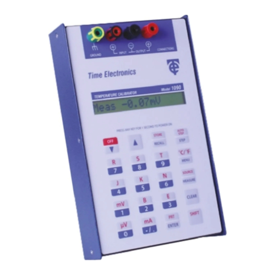
- Page 1 User Manual 1090 Process Calibrator Revision 2207-1 Time Electronics Ltd Unit 5, TON Business Park, 2-8 Morley Road, Tonbridge, Kent, TN9 1RA, United Kingdom. T: +44 (0) 1732 355993 | F: +44 (0) 1732 350198 mail@timeelectronics.co.uk | www.timeelectronics.com...
- Page 2 All rights reserved. Nothing from this manual may be multiplied, or made public in any form or manner, either electronically or hard copy, without prior written consent from Time Electronics Ltd. This also applies to any schematics, drawings and diagrams contained herein.
-
Page 3: Table Of Contents
Display ..............................26 Front Panel Keypad and Connections ....................26 Fuse ..............................26 Specifications ..........................27 Technical Specifications ........................27 General Specifications ......................... 31 1090 Calibration Procedure ......................32 Warranty and Servicing ....................... 34 1090 Process Calibrator Page 3 of 35... -
Page 4: Introduction
The 1090 is supplied in a robust case with a carrying strap. A pocket for this manual and test leads is provided. Full operation, including re-charge, is possible without removal from the case. -
Page 5: Controls
Time Electronics User Manual 1090 Process Calibrator Revision 2207-1 Controls Terminals Connections are made by 4 mm terminals are situated at the top of the instrument. These are clearly labelled for INPUT / OUTPUT / GROUND. Ground is the earth chassis connection. -
Page 6: Keypad Primary And Secondary Functions
1090 Process Calibrator Revision 2207-1 Keypad Primary and Secondary functions Most of the 1090’s keys are dual function. Their primary function is shown in blue on the lower half while the secondary function is shown in red, on the upper half. To access the secondary functions press the ‘SHIFT’... -
Page 7: Control Buttons
Time Electronics User Manual 1090 Process Calibrator Revision 2207-1 Control Buttons Secondary Function Button Primary Function (SHIFT -> BUTTON) Sets keypads to secondary (RED) functions The ’SHIFT’ mode has an automatic time out. This means that it will be cancelled if the secondary function is not selected within a few seconds. - Page 8 Time Electronics User Manual 1090 Process Calibrator Revision 2207-1 Secondary Function Button Primary Function (SHIFT -> BUTTON) When pressed before value input, sets negative polarity. Selects mA When pressed after a value input it sets a decimal point. Input value 0 Selects μV...
-
Page 9: Operating Instructions
Time Electronics User Manual 1090 Process Calibrator Revision 2207-1 Operating Instructions Turning the unit On/Off To Turn On The unit is powered up by pressing and holding any key for longer than 1 second. On power-up, the software version and (mV/mA/Pt) will be displayed for 2 seconds. -
Page 10: Thermocouple Measure
Meas 0.00mV Connecting the Thermocouple Connect the thermocouple cable or compensating cable to the 1090’s input terminals. Thermocouple Selection Select the type of thermocouple that you wish to measure by pressing the SHIFT’ key immediately followed by the thermocouple type. e.g. SHIFT then J to select type J. -
Page 11: Thermocouple Source
Time Electronics User Manual 1090 Process Calibrator Revision 2207-1 Thermocouple Source Select Source mode by pressing ‘SHIFT’ followed immediately by ‘SOURCE’ key. The display will show: Then Src 0.000mV Thermocouple Selection Select the type of thermocouple that you wish to simulate by pressing the SHIFT’ key, immediately followed by the thermocouple type. -
Page 12: Rtd (Pt100) Simulation Measure
Time Electronics User Manual 1090 Process Calibrator Revision 2207-1 RTD (Pt100) Simulation Measure When the unit is turned on it displays the software version number. It then enters its default mode - Millivolt (mV) and displays: Meas 0.00mV Select the PRT by pressing the SHIFT’ key immediately followed by ‘PRT’: Then Meas Pt Over°C... -
Page 13: Rtd (Prt) Source
F’ key. Then Src Pt -148°F For this mode connect the device to be calibrated to the 1090 OUTPUT terminals. The 1090 is now ready to simulate a Pt100 probe. Use the ‘Up/Down’ arrow keys to step change the temperature: Src Pt 20°C... -
Page 14: Μv/Mv Measure
Time Electronics User Manual 1090 Process Calibrator Revision 2207-1 µV/mV Measure Measuring mV Press ‘SHIFT’ followed immediately by ‘mV’ to select mV measure mode. Then Meas 0.00mV The unit is ready to measure mV connected at its INPUT terminals. Measuring µV To measure µV press ‘SHIFT’... -
Page 15: Μv/Mv Source
Time Electronics User Manual 1090 Process Calibrator Revision 2207-1 µV/mV Source mV Source Select Source mode by pressing ‘SHIFT immediately followed by ‘SOURCE’: Then 0.000mV Connect the device to be calibrated to the unit’s OUTPUT terminals. Enter the desired mV values using the numbered keys or ‘Up/Down’ arrow keys. -
Page 16: Ma Measure
Time Electronics User Manual 1090 Process Calibrator Revision 2207-1 mA Measure To select mA Measure mode press ‘SHIFT’ followed immediately by ‘mA’: Then Meas 0. 00mA The unit is ready to measure mA at its INPUT terminals. mA Source and 24 V Process Loop Drive To select Source mode press ‘SHIFT’... -
Page 17: Storing And Recalling Values
3.10 Storing and Recalling Values In source mode the 1090 is able to store and recall up to ten output values. The values may be stored in locations 0 to 9. They can then be recalled manually or automatically. Used in conjunction with the ‘Auto Step’ function the unit can be programmed to output the stored values in sequence pausing at each value. - Page 18 3.10.2 Recalling Values Note: The 1090 stores numeric values, and not the units. Therefore, the correct units i.e. µV, mV etc. must be selected before the recall is done. To recall the stored values the unit must be in ’SOURCE’ mode.
-
Page 19: Step And Auto-Step Functions
Time Electronics User Manual 1090 Process Calibrator Revision 2207-1 3.11 Step and Auto-Step Functions These modes provide a method of manually or automatically stepping through the stored values. When in automatic mode the unit may be programmed to dwell on the stored value for between 1 and 9 seconds before proceeding to the next one. - Page 20 Time Electronics User Manual 1090 Process Calibrator Revision 2207-1 3.11.2 Automatic Stepping Ensure that the unit is in ‘SOURCE’ mode and the desired units are selected. Use the ‘RECALL’ key to set the pointer to the stored locations. Recall 0-9>...
-
Page 21: Inching (Increment/Decrement)
Time Electronics User Manual 1090 Process Calibrator Revision 2207-1 3.12 Inching (Increment/Decrement) The unit has a general-purpose inching function. This adjusts the output in fixed increments of temperature (thermocouples only) or voltage or current. The set-up menu gives the user a choice of three levels of increment: •... - Page 22 Time Electronics User Manual 1090 Process Calibrator Revision 2207-1 3.13.1 Power Auto-off This refers to auto power down state. To conserve battery life the unit will switch off after 5 minutes if set to ‘on’. Enter the setup menu by pressing the ‘MENU’ button: 1) Auto-off Yes To disable this function press ‘ENTER’...
- Page 23 3)CJ Man 25.5°C The 1090 remains in the CJ Manual mode until it is turned off. It will revert to Auto when next turned on. Note: Setting Cold Junction Compensation in °F requires the unit to be in °F units before entering the menu.
- Page 24 Time Electronics User Manual 1090 Process Calibrator Revision 2207-1 3.13.4 Inching (Incrementing/Decrementing) - arrow keys This function sets the step size used by the Up/Down arrow keys. Enter the setup menu by pressing the ‘MENU’ button: 1) Auto-off Yes Use down arrow key, press three times to display function 4: 0.1°,1µ...
-
Page 25: Setting Output Values Between 0.0 And +1.0
Time Electronics User Manual 1090 Process Calibrator Revision 2207-1 3.14 Setting output values between 0.0 and +1.0 It is important that a leading zero is keyed in when setting output positive values between 0.0 and +1.0 The negative sign/decimal point key has a dual function of ‘-’ and ‘.’... -
Page 26: Maintenance
Maintenance Battery Status and Recharging The 1090 is powered from an internal metal hydride battery pack with a capacity of 5 AH. This provides up to 60 hours of continuous operation. The mains recharger will recharge the battery fully in approximately 6 hours, the charging status being indicated by an LED on the charger. -
Page 27: Specifications
Time Electronics User Manual 1090 Process Calibrator Revision 2207-1 Specifications Technical Specifications Measure Accuracy (0.1 °C/F resolution) THERMOCOUPLE TEMPERATURE ACCURACY TYPE RANGE °C °C -200 to 580 -200 to –150 -150 to 750 -200 to 0 0 to 400 -50 to 400... - Page 28 Time Electronics User Manual 1090 Process Calibrator Revision 2207-1 Simulate Accuracy (0.1 °C/F resolution) THERMOCOUPLE TEMPERATURE ACCURACY TYPE RANGE °C °C -210 to 150 0.15 150 to 1200 -270 to 190 190 to 1250 -200 to 150 150 to 400...
- Page 29 Time Electronics User Manual 1090 Process Calibrator Revision 2207-1 Millivolt Measure 0 to 30 mV Accuracy: ± 0.05 % of FS ± 1 digit Resolution: 10 µV Input resistance: 100 kΩ Milliamp Measure 0 to 60 mA Accuracy: ± 0.05 % of FS ± 1 digit Resolution: 20 µA...
- Page 30 Time Electronics User Manual 1090 Process Calibrator Revision 2207-1 Inching Three levels of increment, 0.1, 1 or 10 for °C/°F, and 1, 10 or 100 µV/µA for voltage current. The lowest of these represents the highest setting resolution and provides the most precise control of the output.
-
Page 31: General Specifications
Time Electronics User Manual 1090 Process Calibrator Revision 2207-1 General Specifications Cold Junction Compensation Resolution: 0.1 °C or 0.2 °F. Accuracy: 0.1 °C / 0.2 °F at 22 °C/72°F. Variation with change in ambient: +/- 0.02 °C/F per °C/F Operating Temperature -10 to 40 °C (15 to 105 °F) -
Page 32: 1090 Calibration Procedure
CJ sense point in degrees C. 7) Pt100 Only perform this task if the mA/pt100 board is fitted. Connect a 300.0Ω precision resistor across the output terminals Press ENTER. The 1090 will then restart. 1090 Process Calibrator Page 32 of 35... - Page 33 The PRT/Current board has calibration adjustments on-board for current source and measure and can be supplied ready-calibrated for retrofitting in the field. When a 1090 unit is initially factory calibrated, it is necessary to fit a calibrated PRT/Current option board so that step 8 can be completed (this calibrates for the initial accuracy of the on-board voltage reference).
-
Page 34: Warranty And Servicing
Time Electronics’ total liability is limited to repair or replacement of the product. Note that if Time Electronics determine that the fault on a returned product has been caused by the user, we will contact the customer before proceeding with any repair. - Page 35 Revision 2207-1 Returning Instruments Prior to returning your product please contact Time Electronics. We will issue a return merchandise authorization (RMA) number that is to accompany the goods returning. Further instructions will also be issued prior to shipment. When returning instruments, please ensure that they have been adequately packed, preferably in the original packing supplied.
Need help?
Do you have a question about the 1090 and is the answer not in the manual?
Questions and answers