Table of Contents
Advertisement
Quick Links
Advertisement
Table of Contents

Subscribe to Our Youtube Channel
Related Manuals for Time Electronics 1024


Summary of Contents for Time Electronics 1024
- Page 1 User Manual 1024 DC Current Calibrator Version 1.2 09/22 Time Electronics Ltd Unit 5, TON Business Park, 2-8 Morley Road, Tonbridge, Kent, TN9 1RA, United Kingdom. T: +44 (0) 1732 355993 | F: +44 (0) 1732 350198 mail@timeelectronics.co.uk | www.timeelectronics.com...
- Page 2 All rights reserved. Nothing from this manual may be multiplied, or made public in any form or manner, either electronically or hard copy, without prior written consent from Time Electronics Ltd. This also applies to any schematics, drawings and diagrams contained herein.
-
Page 3: Table Of Contents
Time Electronics 1024 DC Current Calibrator User Manual Contents Introduction ............................4 Description ..............................4 Specifications ............................5 Operation ............................6 Front Panel Controls ..........................6 Operating Procedure ..........................8 Output Noise ............................. 9 Mains Power Unit ........................... 11 Constructional Layout Details ....................... 13 Chopper amplifier module........................ -
Page 4: Introduction
The battery indicator shows a red light when the battery pack should be recharged. Charging is performed by the instruments own internal charger/power supply. Simply plugging the 1024 into a mains supply will charge the batteries. Operation of the 1024 may be continued when plugged into the mains supply. -
Page 5: Specifications
Power supply: Time Electronics power unit type PU2 which is housed in the rear of the 1024. The PU2 will power the 1024 direct from the mains or an internal rechargeable battery pack. The battery is automatically charged when mains power is connected. -
Page 6: Operation
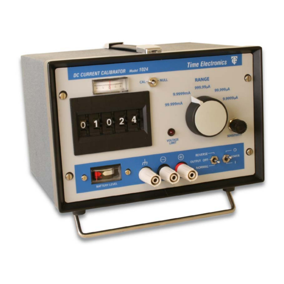
Front Panel Controls 1. Output terminals The 1024 output current is from two front panel 4 mm safety terminals which are suitable for wire compression, 4mm spade, and 4mm shrouded or standard plug insertion. The output current will flow from the + (red) terminal when the polarity switch is ‘normal’ (positive). - Page 7 15 V. Note: When the 1024 is operated from partly discharged batteries, the voltage limit is reduced to a minimum of about 10 V for nearly fully exhausted cells. The battery level indicator gives a clear indication of battery state.
-
Page 8: Operating Procedure
When the 1024 is operating from batteries and required to supply currents in excess 10 mA it is important to check the battery condition with the load connected since the battery’s condition may be adequate for sourcing low output currents but not higher current. -
Page 9: Output Noise
Care must be taken in attempting to understand the cause and effect of noise pick-up on precision current sources such as the 1024, and it is not proposed that this manual should cover them in detail. It is important when confronted with a problem of noise pick-up to stop and think logically about the cause and effect, as a good deal of time can be wasted by indiscriminate screening and earthing. - Page 10 Important Note: When the 1024 is operated from mains power, special attention should be paid to the possibility of noise pick-up occurring. Battery operation is recommended for applications requiring the lowest noise pick-up condition.
-
Page 11: Mains Power Unit
Mains input range: 110 to 250 V AC / 40 to 60 Hz. IEC mains input fuse is 20 mm F1A. The capacity of the rechargeable battery is approximately 600 mA Hrs. This allows about 10 hrs of typical use of the 1024. To fully recharge the battery requires 14 to 16 hours with mains connected. - Page 12 The following procedure should be adopted to convert from 240 V to 110 V. 1) Isolate instrument from mains power, remove rear IEC mains input connector. 2) Remove mains power unit from 1024. 3) Remove PCB metal screening cover. Note: Take care not to short any part of the circuitry when converting a PU2.
-
Page 13: Constructional Layout Details
It is a fully encapsulated module and connections are via a 16-pin connector moulded into it. The modular form of the 1024’s basic circuitry protects it from damage due to adverse conditions and thermal gradients which could give rise to thermal emf errors. Being a non- serviceable part, a replacement module should be ordered from Time Electronics Ltd in the case of failure or malfunctioning of the module (part number 094-9512). -
Page 14: Repair And Recalibration
Spare parts can be obtained from Time Electronics or their authorised dealer. Important Note: It is important that no repair work is undertaken by the customer while the 1024 is under warranty. Such work may invalidate the warranty. - Page 15 PCB The other 2 trimmers are located on the side of the encapsulated module and marked ‘CAL’ and ‘ZERO’. Switch on the 1024 and allow the circuits to stabilise for a few minutes. Ensure that no draughts or direct heating (e.g. sunlight) affect the 1024’s circuitry.
- Page 16 Time Electronics 1024 DC Current Calibrator User Manual 4.2.1 Calibration Procedure For serial numbers 1218K6 and later. Before commencing calibration procedure, fully rotate all 5 digit switches 3-4 times to enable self-cleaning of contacts. 1) Set the 5-digit switches to zero and select 99.999 µA range.
-
Page 17: Warranty And Servicing
Online: Please visit www.timeelectronics.com and select Technical Support from the Contact links. From this page you will be able to send information to the Time Electronics service team who will help and support you. By phone: +44 (0) 1732 355993 By email: mail@timeelectronics.co.uk... - Page 18 User Manual Returning Instruments Prior to returning your product please contact Time Electronics. We will issue a return merchandise authorization (RMA) number that is to accompany the goods returning. Further instructions will also be issued prior to shipment. When returning instruments, please ensure that they have been adequately packed, preferably in the original packing supplied.
Need help?
Do you have a question about the 1024 and is the answer not in the manual?
Questions and answers