Table of Contents
Advertisement
Quick Links
Advertisement
Table of Contents

Subscribe to Our Youtube Channel
Related Manuals for Time Electronics 1010


Summary of Contents for Time Electronics 1010
- Page 1 User Manual 1010 DC Voltage Calibrator Version 1.2 04/22 Time Electronics Ltd Unit 5, TON Business Park, 2-8 Morley Road, Tonbridge, Kent, TN9 1RA, United Kingdom. T: +44 (0) 1732 355993 | F: +44 (0) 1732 350198 mail@timeelectronics.co.uk | www.timeelectronics.com...
- Page 2 All rights reserved. Nothing from this manual may be multiplied, or made public in any form or manner, either electronically or hard copy, without prior written consent from Time Electronics Ltd. This also applies to any schematics, drawings and diagrams contained herein.
-
Page 3: Table Of Contents
Time Electronics User Manual 1010 DC Voltage Calibrator v1.2 Contents Introduction ............................ 4 Description ............................. 4 Specifications ............................5 Power Unit ............................. 6 Circuit Description ..........................6 Applications ............................6 Operation ............................7 Front Panel Controls ..........................7 Operating Procedure ..........................8 Output noise ............................ -
Page 4: Introduction
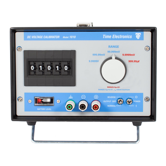
Introduction Description The 1010 is an extremely accurate battery/mains powered voltage calibrator sourcing up to 10 volts in 5 ranges with a resolution up to 0.01µV. Outstanding accuracy, and stability is achieved by using an LTC advanced subsurface Zener bipolar reference source;... -
Page 5: Specifications
Output Polarity: Positive or negative (Normal – Reverse) switch selected. A centre ‘off’ position on this switch provides a short circuit on the output for 1010 voltage source. Output Noise Level: 10, 1 & 0.1V ranges, less than 10 ppm of setting ± 2µV (0-10 Hz). -
Page 6: Power Unit
1010 DC Voltage Calibrator v1.2 Power Unit The 1010 is supplied with a internal mains/battery power unit. This can be configured when ordered for either 115V or 230V AC, 50/60Hz. See section 2.7. Circuit Description The calibrator designed with a precision LTC 5V reference device which offers both outstanding accuracy and temperature coefficient specifications. -
Page 7: Operation
2. Output polarity A change-over toggle switch enables the output polarity to be reversed. A centre position provides a short circuit on the 1010 output terminals. 3. Internal rechargeable battery level The battery level is continuously monitored on a front panel LED indicator which also serves as a supply on-off indication. -
Page 8: Operating Procedure
Case terminal The case terminal is connected only to the instrument case and is isolated from the circuitry. The case provides an overall electrostatic screen for the 1010 and can be earthed as required to improve rejection of noise pick-up. -
Page 9: Output Noise
Hz common mode voltage on the output terminals. Thermal emfs When the 1010 is used to provide precision voltages of less than about 1mV, care must be exercised to avoid errors due to thermal emfs. These occur where temperature differences are present at the junctions of dissimilar metals, e.g. -
Page 10: Mains Power Unit
• Mains input range: 110 - 250V AC 40 - 60 Hz. IEC mains input fuse is 20mm F1A. The capacity of the rechargeable battery is approximately 600mAH. This allows about 40 - 50 hrs continuous use of the 1010. To fully recharge the battery requires 14-16 hours with mains connected. - Page 11 240V to 110V. 1) Isolate instrument from mains power, remove rear IEC mains input connector. 2) Remove 4 rear panel holding screws, withdraw panel / mains power unit from 1010. 3) Remove PCB metal screening cover. Note: Take care not to short any part of the circuitry when converting a PU2.
-
Page 12: Constructional Layout Details
It is a fully encapsulated module and connections are via a 16-pin connector moulded into it. The modular form of the 1010’s basic circuitry protects it from damage due to adverse conditions and thermal gradients which could give rise to thermal emf errors. - Page 13 Time Electronics User Manual 1010 DC Voltage Calibrator v1.2 3.1.2 Module replacement Note: Isolate instrument from mains power, remove rear IEC mains input connector 1) Remove and disconnect power unit located in instrument rear by 4 screws. 2) Remove front locating screws.
-
Page 14: Re-Calibration
9.9999V ranges less than ±100µV Full Scale Fine adjustment of the 1010 output voltage is provided by 4 trimmers. One is located on the module is marked ‘CAL’ and provides equal adjustment of the output voltage for ranges. The other 3 trimmers are located on the front panel pcb, and provide individual adjustment for the 10V, 100mV and 10mV ranges. - Page 15 Time Electronics User Manual 1010 DC Voltage Calibrator v1.2 Fig. 1 1010 Trimmer Layouts 1010 DC Voltage Calibrator Page 15 of 19...
-
Page 16: Calibration Procedure
Time Electronics User Manual 1010 DC Voltage Calibrator v1.2 Calibration Procedure 1) Ensure zero has been set as in section 4.1. 2) Connect power supply. 3) Select 999.99mV range, normal output polarity, and output digits to 99999. 4) Connect a suitable accuracy voltage standard with microvolt null meter to the output terminals. -
Page 17: 10Mv And 1Mv Range Calibration
The attenuation factor is 1000:1. The calibration of the attenuator is via the 10mV range trimmer (VR3). Maximum range of adjustment is 0.16%. The Attenuator is set up when the 1010 is manufactured and normally requires no further adjustment. If, however, any of R2-R5 have been damaged by overload they will require replacing with equivalent types. -
Page 18: Warranty And Servicing
Time Electronics’ total liability is limited to repair or replacement of the product. Note that if Time Electronics determine that the fault on a returned product has been caused by the user, we will contact the customer before proceeding with any repair. - Page 19 Returning Instruments Prior to returning your product please contact Time Electronics. We will issue a return merchandise authorization (RMA) number that is to accompany the goods returning. Further instructions will also be issued prior to shipment. When returning instruments, please ensure that they have been adequately packed, preferably in the original packing supplied.
Need help?
Do you have a question about the 1010 and is the answer not in the manual?
Questions and answers