Table of Contents
Advertisement
Quick Links
Instruction Manual
Form 5781
June 2013
Type EZL Pressure Reducing Regulator for
Low Pressure Applications
W8962
Introduction
Scope of Manual
This manual provides installation, startup,
maintenance, and parts ordering information for the
Type EZL pressure reducing regulator. Information on
other equipment used with this regulator is found in
separate manuals.
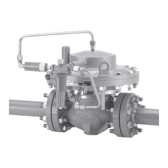
Figure 1. Type EZL Pressure Reducing Regulator
Product Description
Type EZL regulators are accurate pilot-operated,
pressure balanced, and soft seated regulators.
They are designed for use in natural gas distribution
applications such as district regulating stations and
commercial/industrial meter sets. They provide low
differential, smooth, reliable operation, tight shutoff,
and long life.
www.fisherregulators.com
Type EZL
Advertisement
Table of Contents

Related Manuals for Fisher EZL


Summary of Contents for Fisher EZL
- Page 1 Instruction Manual Form 5781 June 2013 Type EZL Pressure Reducing Regulator for Low Pressure Applications W8962 Figure 1. Type EZL Pressure Reducing Regulator Introduction Scope of Manual Product Description This manual provides installation, startup, Type EZL regulators are accurate pilot-operated, maintenance, and parts ordering information for the pressure balanced, and soft seated regulators.
-
Page 2: Specifications
CL250B RF 500 psig / 34.5 bar 1. Structural Design Rating is the rating for the main valve body. The Type EZL complete assembly is limited to 285 psig / 19.7 bar. 2. Available only on 2-inch / DN 50 body Table 2. - Page 3 OUTLET PRESSURE LOADING PRESSURE ATMOSPHERIC PRESSURE INLET PRESSURE OUTLET PRESSURE Figure 2. Type EZL with Type 6352 Pilot and Type P590 Pilot Supply Filter Operational Schematic ATMOSPHERIC PRESSURE LOADING PRESSURE Principle of Operation the actuator diaphragm escapes downstream through the bleed restriction in the pilot.
-
Page 4: Monitoring Systems
LOADING PRESSURE ATMOSPHERIC PRESSURE ATMOSPHERIC PRESSURE Figure 3. Type EZL with Type 61L Pilot and Type P590 Pilot Supply Filter Operational Schematic Wide-Open Monitoring Systems (Figure 4) the aid of a pressure gauge to monitor downstream pressure. The shutoff valve downstream of the There are two types of wide-open monitoring systems: regulator must not be completely closed;... - Page 5 Type EZL with the checked for proper operation. appropriate pilot for the downstream regulator.
-
Page 6: All Installations
All Installations parts may result if this regulator is A Type EZL regulator bleeds no gas to atmosphere overpressured or is installed where during normal operation, thus making the regulator service conditions could exceed the limits... - Page 7 Type EZL Note 5. Run a 3/8-inch / 9.5 mm outer diameter or larger pilot supply line from the upstream pipeline to When upgrading Fisher control valves, ® the filter inlet as shown in Figure 3, bushing the such as Types ET, ED, and ES make sure line down to fit the 1/4 inch threaded NPT filter the body is in the flow up direction.
- Page 8 Type EZL Regardless of which regulator is used as the monitor, regulator into operation must be planned accordingly if the downstream system is it should be equipped with a pilot supply regulator pressurized by another regulator or by a set to limit the pilot supply pressure to 10 to 15 psig / manual bypass.
-
Page 9: Pilot Adjustment
Replace the casings (keys 11 and 5) off the Type EZL pilot closing cap, if necessary. body (key 1). The 2-inch / DN 50... - Page 10 Type EZL Table 3. Torque Specifications TORQUE SPECIFICATIONS, FOOT-POUNDS / N•m Indicator Fitting Stud Nuts Socket Head Cap Cap Screws Cap Screws Socket Head Cap Body Size (key 56) or (key 26) Screws (key 16) (keys 21 and 39) (key 6)
- Page 11 Type EZL Actuator Assembly Maintenance 9. Slide the outlet plate (key 19) onto the sleeve (key 14) and slide the sleeve into the lower actuator 1. Make a mark on the upper actuator casing casing (key 5). Place the disk holder (key 30)
-
Page 12: Pilot Maintenance
1. Lubricant and sealant must be selected such that they meet the temperature requirements. Figure 6. Travel Indicator Assembly Drawings Type EZL Travel Indicator Maintenance 4. Insert the travel indicator stem (key 54) and spring collet (key 57) back into the diaphragm head A new and improved version of the travel indicator groove. - Page 13 Type EZL Note pilot into three sections; spring case (key 1), body (key 2), and bottom cover (key 3). The body (key 1) may remain on the pipe nipple (key 21, Figure 8 or key 24, Figure 9) 4. To inspect the two diaphragms (keys 14 and 15) unless the entire pilot is replaced.
-
Page 14: Parts Ordering
(key 8), the control spring (key 9), and, if used, the diaphragm limiter (key 10). Each Type EZL regulator is assigned a serial number, which can be found on the nameplate. Refer to the 3. Remove the diaphragm assembly (key 7) and number when contacting your local Sales Office for inspect the diaphragm. - Page 15 Type EZL Description Part Number Description Part Number Seat and Diaphragm Parts Kits Body (continued) 2 and 3 inch / DN 50 and 80 (includes key numbers: 4 inch / DN 100 (continued) 4, 7, 8, 9, 12B, 15, 17, 20, 28, 29, 30, 34, 70, and 76)
- Page 16 Type EZL Description Part Number Description Part Number Cap Screw Bolt (2 required) 2 inch / DN 50 (14 required) 18B3065X012 2 inch / DN 50 GE07223X012 3 and 4 inch / DN 80 and 100 (22 required) 1A514724052 3 and 4 inch / DN 80 and 100...
- Page 17 S1 = ANAEROBIC METHACRYLATE SEALANT FOR NUTS AND BOLTS S2 = ANAEROBIC METHACRYLATE SEALANT FOR THREADS S3 = MULTI-PURPOSE PTFE THREAD SEALANT 1. Lubricant and sealants must be selected such that they meet the temperature requirements. Figure 7. Type EZL Main Valve Assembly...
- Page 18 Type EZL GE10987-8 Figure 7. Type EZL Main Valve Assembly (continued) 35A8889 35A6236 DETAIL OF TYPE 6354M OR 6354H PILOT COMPLETE TYPE 6352, 6353, OR 6354L PILOT Figure 8. Types 6352 through 6354H Pilot Assemblies...
- Page 19 Type EZL Types 6352, 6353, 6354L, 6354M, and 6354H Pilots (Figure 8) Description Part Number Description Part Number Parts kit (included are: valve plug, key 4; diaphragm Adjusting Screw assembly, key 5; body plug gasket, key 12; bellows Type 6352 or 6353 10B7192X012 O-ring, key 17;...
- Page 20 Type EZL 30A6327 20A6328 DETAIL OF CAPPED ADJUSTING SCREW OPTION DETAIL OF HANDWHEEL OPTION TYPE 61L PILOT 20A6326 Figure 9. Type 61L Pilot Assembly...
- Page 21 Type EZL 61 Series Pilots (Figure 9) Description Part Number Description Part Number O-ring Seal Relay Spring Case Standard and corrosive trim 1B885506992 Types 61L, 61LD, and 61LE 1B983919012 Pressure loaded corrosive trim 1B8855X0012 Type 61H Relay Spring Standard adjusting screw...
- Page 22 Type EZL BLEED SENSE (EXHAUST) (CONTROL) PORT IN PORT PORT TYPES 161M AND 161EBM IN PORT GAUGE OR OPTIONAL OUT (CONTROL) PORT OUT PORT (CONTROL) TYPE 161M 30B4395-E C0806 APPLY LUBRICANT (L) L2 = ANTI-SEIZE LUBRICANT L3 = EXTREME LOW TEMPERATURE BEARING GREASE TYPE 161EBM 1.
- Page 23 Type EZL Types 161M and 161EBM Pilots (Figure 10) Description Part Number Type 161M Pilot Parts Kit (included are keys 4, 6, 7, 15, 17, 19, and 22) For 5 to 15 or 10 to 125 psig / 0.34 to 1.0 or 0.69 to 8.6 bar control spring range...
- Page 24 For further information visit www.emersonprocess.com/regulators The Emerson logo is a trademark and service mark of Emerson Electric Co. All other marks are the property of their prospective owners. Fisher is a mark owned by Fisher Controls International LLC, a business of Emerson Process Management.
Need help?
Do you have a question about the EZL and is the answer not in the manual?
Questions and answers