Table of Contents
Advertisement
Instruction Manual
Form 5621
May 1995
Type 1078 Declutchable Manual Actuator
Contents
. . . . . . . . . . . . . . . . . . . . . . . . . . . . . . .
. . . . . . . . . . . . . . . . . . . . . . . . . . . . .
. . . . . . . . . . . . . . . . . . . . . . . . . . . . . . . . . .
. . . . . . . . . . . . . . . . . . . . . . . . . . . . . . .
. . . . . . . . . . . . . . . . . . . . . . . . . . . . . . . .
. . . . . . . . . . . . . . . . . . . . . . . . . . . . . . . . . .
. . . . . . . . . . . . . . . . . . . . . . . . . . . . . . . .
. . . . . . . . . . . . . . . . . . . . . . . . . . . . . . . .
. . . . . . . . . . . . . . . . . . . . . . . . . . . . .
. . . . . . . . . . . . . . . . . . . . . . . . . . . . . . . .
. . . . . . . . . . . . . . . . . . . . . . . . . . .
. . . . . . . . . . . . . . . . . . . . . . . . . . . . . . . . .
. . . . . . . . . . . . . . . . . . . . . . .
. . . . . . . . . . . . . . . . . . . . . . . . . . . . . .
Introduction
Scope of Manual
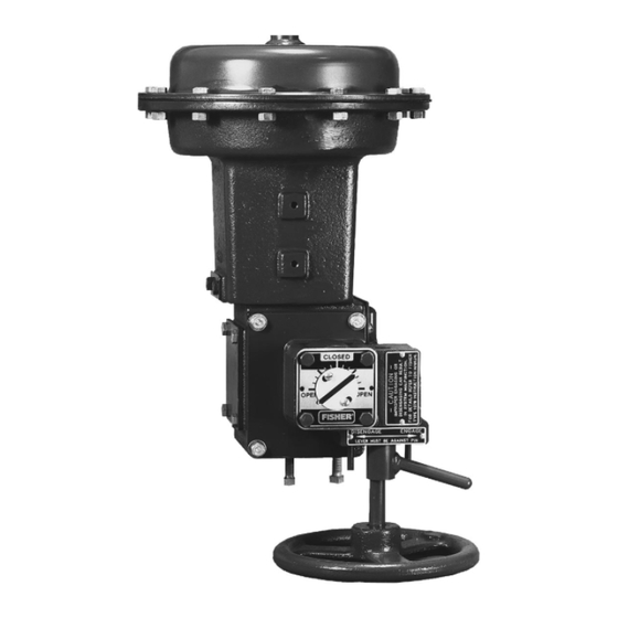
This instruction manual includes installation, operation,
and maintenance information for the Type 1078 de-
clutchable manual actuator (figure 1). Refer to sepa-
rate instruction manuals for instructions covering the
power actuator and control valve.
1
1
3
3
8
8
. . . . . . . . . . . . . . . . .
9
10
10
. . . . . . . . . . . . . .
10
. . . . . . . . . . .
10
11
11
11
12
. . . . . . . . . . . . . . . . . .
12
16
16
. . . . . . .
16
W6244-1/IL
Figure 1. Type 1078 Manual Actuator Mounted on
a Type 1052 Size 33 Actuator
Only personnel qualified through training or experience
should install, operate, and maintain a Type 1078 de-
clutchable manual actuator. If there are any questions
about these instructions, contact your Fisher Controls
sales office or sales representative before proceeding.
Type 1078
Advertisement
Table of Contents

Related Manuals for Fisher 1078


Summary of Contents for Fisher 1078
-
Page 1: Table Of Contents
Only personnel qualified through training or experience and maintenance information for the Type 1078 de- should install, operate, and maintain a Type 1078 de- clutchable manual actuator (figure 1). Refer to sepa- clutchable manual actuator. If there are any questions... - Page 2 Type 1078 Table 1. Specifications Available Configurations Standard Mounting Positions Type 321 (sizes 60 and 80) : handwheel down Direct and reverse acting; see Handwheel Rotation (std) or handwheel right-hand or left-hand mount in this specification table (optional) Type 354 (sizes 60 and 80)
-
Page 3: Description
Type 1078 W6283/IL Figure 2. Type 1078 Declutchable Manual Actuator Mounted on a Type 1052 Size 40 Actuator and Design V500 Valve Description tuator sector, and spacers secure the shaft in the ap- propriate position. The Type 1078 manual actuator, shown in figures 1... - Page 4 The Type 1066 actuator requires installation of appropriate hub assembly. 3. Compare table value with torque requirements of the valve plus the torque required to compress the power actuator spring (from Fisher Controls Catalog 14). Note that dynamic torque of the valve may have a positive or negative effect on total torque required.
- Page 5 2. Compare table value with torque requirements of the valve plus the torque required to compress the power actuator spring (from Fisher Controls Catalog 14). Note that dynamic torque of the valve may have a positive or negative effect on total torque required.
- Page 6 Type 1078 Table 4. Types 1061, 321, and 354 Actuator Size Selection and Specifications for Sizes 2A, 1A, B, C, D, and II -FA HANDWHEEL MANUAL WHEEL-RIM-FORCE TURNS FOR POWER HANDWHEEL MAXIMUM ACTUA- ROTATION SHAFT SIZE SHAFT SIZE GEAR GEAR...
- Page 7 63.5 1. Compare table value with torque requirements of the valve plus the torque required to compress the power actuator spring (from Fisher Controls Catalog 14). Note that dynamic torque of the valve may have a positive or negative effect on total torque required.
-
Page 8: Installation
Type follow apply only to power actuators which were not 1078 manual actuator. Failure to use the ordered specifically for use with the Type 1078 manual thicker plate may result in damage to actuator. Proceed as appropriate: internal components and unreliable per- formance of the power actuator. -
Page 9: Installing The Manual Actuator
Type 1078 Installing the Manual Actuator 4. Note whether the valve disk or ball is in the open or closed position. 5. Rotate the handwheel to move the drive sleeve WARNING gear and travel indicator to the position that corre- sponds with the position of the valve disk or ball. -
Page 10: Operation
(Note that stop pins are not avail- detent mechanism. (Note that stop pins are not avail- able on Type 1078 size II -FA actuators.) able on Type 1078 size II -FA actuators.) -
Page 11: Maintenance
Coat the worm, the drive sleeve gear teeth, and the bearing surfaces of the gearbox housing The interior parts of the Type 1078 manual actuator should be lubricated on a regular schedule with a qual- and worm with a quality gear lubricant. -
Page 12: Parts List
Type 1078 Description Part Number Parts List Actuator Fits Type 1051 (size 60), Type 1052 (sizes 60 & 70), Manual Actuator Type 1061 (sizes 40, 60, & 68), and Types 321 & 354 (size 60) Assembly (figures 2 & 3) For size 2A Styles F &... - Page 13 Type 1078 41B0028-A/DOC Figure 3. Type 1078 Declutchable Manual Actuator Mounted on a Type 1066 Actuator Description Part Number Description Part Number Actuator (continued) Actuator Fits Type 1051 (size 60), Type 1052 (sizes 60 & 70), For size Type 1061 (sizes 40, 60, & 68), and Types 321 & 354 (size 60) Styles F &...
- Page 14 Type 1078 Figure 4. T ype 1078 Declutchable Manual Actuator , Sizes 2A, 1A, B, C, and D Figure 5. T ype 1078 Declutchable Manual Actuator , Size II -FA Description Part Number Description Part Number Pin, steel Travel Indicator scale, stainless steel...
- Page 15 Type 1078 TYPE 1078 MANUAL ACTUATOR POWER ACTUATOR LEVER SHAFT ADAPTOR KEY 9 NOTE: PROPER ASSEMBLY OF SHAFT ADAPTER KEY 9 WHEN REQUIRED B2458/IL Figure 6. Lever and Splined Adaptor Description Part Number Description Part Number Travel Indicator Pointer, stainless steel...
-
Page 16: Field Mounting Parts
1. Power actuator requires a lever for 1-1/4 inch valve shaft. 2. Power actuator requires a lever for 2-inch valve shaft. Fisher, Fisher-Rosemount, and Managing the Process Better are marks owned by Fisher Controls, International, Inc. or Fisher-Rosemount Systems, Inc. Fisher Controls International, Inc.; 1986, 1995; All Rights Reserved.
Need help?
Do you have a question about the 1078 and is the answer not in the manual?
Questions and answers