Table of Contents
Advertisement
Quick Links
Instruction Manual
D103557X012
™
Fisher
FIELDVUE
Controller
This manual applies to
Instrument Level
Device Type
Device Revision
Hardware Revision
Firmware Revision
DD Revision
. . . . . . . . . . . . . . . . . . . . . . . . . . . . . .
. . . . . . . . . . . . . . . . . . . . . . . . . . . . . . . . . .
. . . . . . . . . . . . . . . . . . . . . . . . . . . . . . . .
. . . . . . . . . . . . . . . . . . . . . . . . . . .
. . . . . . . . . . . . . . . . . . . . . . . . . . .
. . . . . . . . . . . . . . . . . . . . . . . . . . . . . . . . .
. . . . . . . . . . . . . . . . . . . . . . . . . . . .
. . . . . . . . . . . . . . . . . . . . . . . .
. . . . . . . . . . . . . . . . . . . . . . . . .
. . . . . . . . . . . . . . . . . . . . . . . . . . . . . . . . .
. . . . . . . . . . . . . . . . . . . . . . . . . . . . . . .
. . . . . . . . . . . . . . . . . . . . . . . . . . . . . . .
. . . . . . . . . . . . . . . . . . . . . . . .
. . . . . . . . . . . . . . . . . . . . . . . .
. . . . . . . . . . . . . . . . . . . . . . . . . . . . . . . .
. . . . . . . . . . . . . . . . . . . . . . . . . . .
. . . . . . . . . . . . . . . . . . . . . . . . .
. . . . . . . . . . . . . . . . . . . . . . . . . . . . . . . . . .
. . . . . . . . . . . . . . . . . . . . . . . . . . .
. . . . . . . . . . . . . . . . . . . . . . . . . . . . .
www.Fisher.com
™
DVC6200 SIS Digital Valve
SIS
130a
1 & 2
2
4, 5 & 6
3, 4 & 5
. . . . . . . . . . . . . . . . .
. . . . . . . . . . . . . . . . . . . . .
. . . . . . . . . . . . . . . .
. . . . . . . . . . . . . .
. . . . . . . . . . . . . . . . . .
. . . .
. . . . . . . . . . . . . . . . .
. . . . . . . . . . . . . . . . . . . . . . .
. . . . . . . . . . . . . . .
. . . . . . . . . . . . . . . . . . . . . . .
. . . . . . . . . . . . . . . . . . . .
3
3
3
X0079
3
3
4
7
8
9
9
. . . . . . . . . . . . . . . . . . . . . . . . . . . . . . . . . . . .
9
9
10
12
11
13
13
. . . . . . . . . . . . . . . . . . . . . . . . . . . . . . . . . . .
13
15
15
15
17
17
17
17
17
18
18
18
18
18
DVC6200 SIS Digital Valve Controller
. . . . . . . . . . . . . . . . . . . . . .
. . . . . . . . . . . . . . . .
. . . . . . . . . . . . . . . . . . . . . . . .
. . . . . . . . . . . . . . . . . . . . . .
. . . . . . . . . . . . . . . . . . . . . . . . . .
. . . . . . . . . . . . . . . . . . . . . . . . . . .
. . . . . . . . . . . . . . . . . . . . . . . .
. . . . . . . . . . . . . . . . . . . . . . . . . .
. . . . . . . . . . . . . . . . . . . . . . .
. . . . . . . . . . . . . . . . . .
. . . . . . . . . . . . . . . . . . . . . . . . . . . .
. . . . . . . . . . . . . . . . . . . .
. . . . . . . . . . . . . .
. . . . . . . . . . . . . . . . . . . . .
. . . . . . . . . . . . . . . . . . . . . . . . . . . .
. . . . . . . . . . . . . . . . . . . . . . . . . . . . . . . . .
. . . . . . . . . . . . . . . . . . . .
April 2016
19
19
19
21
21
21
21
24
24
27
27
30
30
. . . . . . . . . . . .
30
31
31
31
31
32
34
Advertisement
Table of Contents
Troubleshooting

Related Manuals for Fisher FIELDBUE DVC6200


Summary of Contents for Fisher FIELDBUE DVC6200
-
Page 1: Table Of Contents
Instruction Manual DVC6200 SIS Digital Valve Controller D103557X012 April 2016 ™ ™ Fisher FIELDVUE DVC6200 SIS Digital Valve Controller This manual applies to Instrument Level Device Type 130a Device Revision 1 & 2 Hardware Revision Firmware Revision 4, 5 & 6 DD Revision 3, 4 &... -
Page 2: Contents
Instruction Manual DVC6200 SIS Digital Valve Controller April 2016 D103557X012 Contents (continued) Component Replacement ....Removing the Module Base ....Section 4 Calibration . -
Page 3: Section 1 Introduction
This instruction manual describes using the 475 Field Communicator to set up and calibrate the instrument. You can also use Fisher ValveLink software to setup, calibrate, and diagnose the valve and instrument. For information on using ValveLink software with the instrument refer to ValveLink software help or documentation. -
Page 4: Specifications
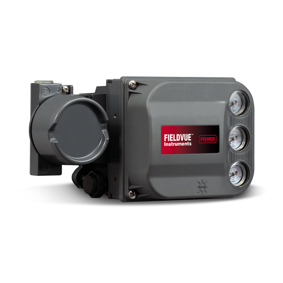
Instruction Manual Introduction April 2016 D103557X012 Figure 1‐1. FIELDVUE DVC6200 SIS Digital Valve Controller Mounted on a Bettis Quarter-Turn Actuator X0079 Specifications WARNING Refer to table 1‐1 for specifications. Incorrect configuration of a positioning instrument could result in the malfunction of the product, property damage or personal injury. - Page 5 Pressure Dew Point: Class 3 or at least 10_C less than ntegral mounting to Fisher rotary actuators the lowest ambient temperature expected Integral mounting to the Fisher GX control valve and actuator system Output Signal DVC6200 SIS digital valve controllers can also be...
- Page 6 Environmental Conditions: Installation Category I Connections Electrical Classification Supply Pressure: 1/4 NPT internal and integral pad for Hazardous Area Approvals mounting Fisher 67CFR regulator Output Pressure: 1/4 NPT internal CSA— Intrinsically Safe, Explosion-proof, Division 2, Tubing: 3/8‐inch recommended Dust Ignition-proof Vent: 3/8 NPT internal FM—...
-
Page 7: Related Documents
This section lists other documents containing information related to the DVC6200 SIS digital valve controller. These documents include: D Bulletin 62.1:DVC6200 SIS - Fisher FIELDVUE DVC6200 SIS Digital Valve Controller (D103555X012) D Bulletin 62.1:DVC6200(S1) Fisher FIELDVUE DVC6200 Digital Valve Controller Dimensions (D103543X012) D Fisher FIELDVUE DVC6200 Series Digital Valve Controller Quick Start Guide (D103556X012) -
Page 8: Educational Services
Introduction April 2016 D103557X012 D Fisher LCP100 Instruction Manual (D103272X012) D Fisher LC340 Instruction Manual (D102797X012) D Fisher HF340 Filter Instruction Manual (D102796X012) D 475 Field Communicator User's Manual D ValveLink Software Help or Documentation All documents are available from your Emerson Process Management sales office. -
Page 9: Section 2 Wiring Practices
Instruction Manual Wiring Practices D103557X012 April 2016 Section 2 Wiring Practices22 Logic Solver or Control System Requirements There are several parameters that should be checked to ensure the logic solver or control system is compatible with the DVC6200 SIS digital valve controller. HART Filter / Line Conditioner Depending on the logic solver or control system and operational mode of the DVC6200 SIS digital valve controller, a line conditioner or HART filter may be required. -
Page 10: Compliance Voltage
Instruction Manual Wiring Practices April 2016 D103557X012 Figure 2‐1. Determining Voltage Available at the Instrument TOTAL LOOP COMPLIANCE VOLTAGE CABLE RESISTANCE CONTROL SYSTEM VOLTAGE INTRINSIC SAFETY LINE CONDITIONER AVAILABLE AT THE BARRIER OR HART FILTER INSTRUMENT (if used) (if used) Calculate Voltage Available at the Instrument as follows: Example Calculation 18.5 volts (at 21.05 mA for Honeywell TDC2000) -
Page 11: Maximum Cable Capacitance
Instruction Manual Wiring Practices D103557X012 April 2016 2. Set the system to provide maximum output current. 3. Increase the resistance of the 1 kW potentiometer, shown in figure 2‐2, until the current observed on the milliammeter begins to drop quickly. 4. -
Page 12: Auxiliary Terminal Wiring Length Guidelines
Instruction Manual Wiring Practices April 2016 D103557X012 Auxiliary Terminal Wiring Length Guidelines The Auxiliary Input Terminals of a DVC6200 SIS can be used with an LCP100 local control panel or a locally‐mounted switch for initiating a partial stroke test. Some applications require that the switch or local control panel be installed remotely from the DVC6200 SIS. -
Page 13: Lcp100 Control Panel
LCP100 Local Control Panel Installation The Fisher LCP100 Local Control Panel has four (4) mounting holes for on‐site mounting of the device. The LCP100 must be installed so that the wiring connections are on the bottom to prevent accumulation of moisture inside the box. - Page 14 Instruction Manual Wiring Practices April 2016 D103557X012...
-
Page 15: Section 3 Configuration
Instruction Manual Configuration D103557X012 April 2016 Section 3 Configuration Guided Setup Field Communicator Configure > Guided Setup (2‐1) To quickly setup the instrument, the following procedures will guide you through the process. D Device Setup—This procedure is used to configure actuator and valve information, calibrate the valve assembly, and assign the tuning set for the valve assembly. - Page 16 Instruction Manual Configuration April 2016 D103557X012 Table 3‐2. Possible Configurations for a FIELDVUE DVC6200 SIS Digital Valve Controller operated by 4‐20 mA Device Setup Configuration Operating Conditions Status Monitoring Partial Stroke Zero Power Travel Set Relay Type Input Current Actual Valve Travel Travel Start Point Condition...
-
Page 17: Mode And Protection
Instruction Manual Configuration D103557X012 April 2016 Mode and Protection Field Communicator Configure > Manual Setup > Mode and Protection (2‐2‐1) Instrument Mode There are two instrument modes for the DVC6200 SIS; In Service or Out of Service. In Service is the normal operating mode such that the instrument follows the 420 mA or 24 VDC control signal. -
Page 18: Serial Numbers
Instruction Manual Configuration April 2016 D103557X012 For the Field Communicator to be able to communicate with a device whose polling address is not 0, it must be configured to automatically search for all or specific connected devices. Serial Numbers D Instrument Serial Number—Enter the serial number on the instrument nameplate, up to 12 characters. D Valve Serial Number—Enter the serial number for the valve in the application with up to 12 characters. -
Page 19: Travel/Pressure Control
Instruction Manual Configuration D103557X012 April 2016 Travel/Pressure Control Field Communicator Configure > Manual Setup > Travel/Pressure Control (2‐2-3) End Point Pressure Control (EPPC) D EPPC Enable—Select Yes or No. End Point Pressure Control allows the digital valve controller to pull back from saturation of the pneumatic output after reaching the travel extreme. - Page 20 Instruction Manual Configuration April 2016 D103557X012 modifies the overall valve and instrument characteristic. However, if you select the linear input characteristic, the overall valve and instrument characteristic is the characteristic of the valve, which is determined by the valve trim (i.e., the plug or cage).
-
Page 21: Dynamic Response
Instruction Manual Configuration D103557X012 April 2016 Dynamic Response D SP Rate Open—Maximum rate (% of valve travel per second) at which the digital valve controller will move to the open position regardless of the rate of input current change. A value of 0 will deactivate this feature and allow the valve to stroke open as fast as possible. - Page 22 Stabilize/Optimize or Performance Tuner may be used to achieve the desired results more rapidly than manual Expert tuning. Table 3‐5 provides tuning set selection guidelines for Fisher and Baumann actuators. These tuning sets are only recommended starting points. After you finish setting up and calibrating the instrument, you may have to select either a higher or lower tuning set to get the desired response.
- Page 23 (Window‐mount) 60, 70 Depends upon pneumatic connections. See 1061 Piston Dbl w/o Spring description for Travel Sensor Motion Fisher 68, 80, 100, 130 Mounting Style Travel Sensor Motion Away from the top of the instrument Towards the top of the...
-
Page 24: Integral Settings
Instruction Manual Configuration April 2016 D103557X012 D Stabilize/Optimize WARNING During Stabilize/Optimize the valve may move, causing process fluid or pressure to be released. To avoid personal injury and property damage caused by the release of process fluid or pressure, isolate the valve from the process and equalize pressure on both sides of the valve or bleed off the process fluid. - Page 25 Instruction Manual Configuration D103557X012 April 2016 Table 3‐6. Feedback Connection Options Travel Range Magnet Assembly Inch Degrees SStem #7 4.2-7 0.17-0.28 SStem #19 8-19 0.32-0.75 SStem #25 20-25 0.76-1.00 SStem #38 26-38 1.01-1.50 SStem #50 39-50 1.51-2.00 SStem #110 51-110 2.01-4.125 SStem #210 110-210...
- Page 26 Instruction Manual Configuration April 2016 D103557X012 Select Clockwise/Toward Bottom, or Counterclockwise/Toward Top. Travel Sensor Motion establishes the proper travel sensor rotation. For quarter‐turn actuators determine rotation by viewing the rotation of the magnet assembly from the back of the instrument. Note Travel Sensor Motion in this instance refers to the motion of the magnet assembly.
-
Page 27: Sis/Partial Stroke Test
Instruction Manual Configuration D103557X012 April 2016 SIS/Partial Stroke Test Field Communicator Configure > Manual Setup > SIS/Partial Stroke (2-2-6) Partial Stroke Test (PST) D PST Pressure Limit— This defines the actuator pressure at which a partial stroke test will abort. This prevents the DVC6200 SIS from exhausting (or building) excessive pressure to the actuator in an attempt to move a stuck valve. - Page 28 Instruction Manual Configuration April 2016 D103557X012 3. Run a partial stroke test. 4. Select the Press/Time radio button on the partial stroke graph (refer to the example in figure 3‐3, bottom plot). If the actuator pressure starts high and moves low, find the minimum actuator pressure (Pmin). If the actuator pressure starts low and moves high, find the maximum actuator pressure (Pmax).
- Page 29 Instruction Manual Configuration D103557X012 April 2016 Figure 3‐3. Example Time Series Plots of Travel Set Point, Travel, Error, and Actuator Pressure TEST START POINT ACTUAL TRACE FROM TEST (TYPICAL) MAX. TRAVEL MOVEMENT (5%) TEST SPEED (% / SEC) TEST PAUSE TIME (SEC) TIME (SEC) ACTUAL TRACE FROM TEST (TYPICAL)
-
Page 30: Sis Options
Instruction Manual Configuration April 2016 D103557X012 SIS Options D Auto Test Interval—This is the interval of time (in days) between partial stroke tests that are automatically run by the digital valve controller, subject to the device being powered up. A value of 0 disables this feature. D LoopInitiated PST—When this feature is enabled, the digital valve controller will run a partial stroke test if the loop current is set to within +/0.5% of the PST trip point. -
Page 31: Switch Configuration
Instruction Manual Configuration D103557X012 April 2016 configured as a transmitter, the output can be configured to drive high (22.5 mA) or low (3.6 mA). When configured as a switch, the output can be configured to drive Closed or Open. Note On loss of positioner power, the switch circuit will always go to the open state. -
Page 32: Alert Setup
Instruction Manual Configuration April 2016 D103557X012 D Burst Command—This defines which HART command is configured for burst reporting. There are three options to choose from. When using a TriLoop, select the third option. - Analog Input (Command 1) - Loop Current / Travel (Command 2) - Loop Current / PV / SV / TV / QV (Command 3) Note Access to information in the instrument is normally obtained through the poll/response of HART communication. - Page 33 Instruction Manual Configuration D103557X012 April 2016 Table 3‐9. Default Alert and Shutdown Settings Alert Default Alert Setting Default Shutdown Setting Travel Sensor Failure Enabled Disabled Temperature Sensor Failure Enabled Disabled Minor Loop Sensor Failure Enabled Disabled Pressure Sensor Failure Enabled Disabled Drive Current Failure Enabled...
- Page 34 Instruction Manual Configuration April 2016 D103557X012 Change to HART 5 / Change to HART 7 Field Communicator Service Tool > Maintenance > Change to HART 5 / Change to HART 7 (3-5-3) This procedure changes the instrument from HART Universal Revision 5 to HART Universal Revision 7 (or vice versa). Before proceeding, verify that your systems are prepared to support HART Universal Revision 7 devices.
-
Page 35: Section 4 Calibration
Instruction Manual Calibration D103557X012 April 2016 Section 4 Calibration Calibration Overview When a DVC6200 SIS digital valve controller is ordered as part of a control valve assembly, the factory mounts the digital valve controller on the actuator and connects the necessary tubing, then sets up and calibrates the controller. For digital valve controllers that are ordered separately, recalibration of the analog input or pressure sensors generally is unnecessary. -
Page 36: Travel Calibration
Instruction Manual Calibration April 2016 D103557X012 Travel Calibration If a double‐acting relay is used, you will be prompted to run the relay adjustment when auto or manual calibration is selected. Select Yes to adjust the relay, select No to proceed with calibration. For additional information, refer to Relay Adjustment on page 41. -
Page 37: Manual Calibration
Instruction Manual Calibration D103557X012 April 2016 Manual Calibration Two procedures are available to manually calibrate travel: D Analog Adjust— This procedure is used when you can manually change the 4-20 mA current source to move the valve. D Digital Adjust— This procedure is used when the 4-20 mA current source cannot be manually changed. Analog Calibration Adjust Connect a variable current source to the instrument LOOP + and LOOP - terminals. -
Page 38: Pushbutton Calibration
Instruction Manual Calibration April 2016 D103557X012 2. From the adjustment menu, select the direction and size of change required to set the travel at 0%. Selecting large, medium, and small adjustments causes changes of approximately 10.0%, 1.0%, and 0.1%, respectively. If another adjustment is required, repeat step 2. -
Page 39: Sensor Calibration
Instruction Manual Calibration D103557X012 April 2016 Sensor Calibration Pressure Sensors Note The pressure sensor is calibrated at the factory and should not require calibration. Output Pressure Sensor To calibrate the output pressure sensor, connect an external reference gauge to the output being calibrated. The gauge should be capable of measuring maximum instrument supply pressure. -
Page 40: Analog Input Calibration
Instruction Manual Calibration April 2016 D103557X012 Supply Pressure Sensor To calibrate the supply pressure sensor, connect an external reference gauge to the output side of the supply regulator. The gauge should be capable of measuring maximum instrument supply pressure. Follow the prompts on the Field Communicator display to calibrate the instrument's supply pressure sensor. -
Page 41: Relay Adjustment
Instruction Manual Calibration D103557X012 April 2016 If the displayed value does not match the current source, press OK, then repeat this step (step 4) to further adjust the displayed value. When the displayed value matches the current source, select Done and go to step 5. 5. -
Page 42: Single-Acting Relays
Instruction Manual Calibration April 2016 D103557X012 Figure 4‐1. Relay A Adjustment (Shroud Removed for Clarity) LOW BLEED RELAY DOES NOT HAVE BLEED HOLES FOR SINGLE‐ACTING DIRECT RELAYS: ROTATE ADJUSTMENT DISC IN THIS DIRECTION UNTIL IT CONTACTS THE BEAM FOR DOUBLE‐ACTING RELAYS: ROTATE ADJUSTMENT DISC IN THIS DIRECTION TO DECREASE OUTPUT PRESSURE... -
Page 43: Pst Calibration
Instruction Manual Calibration D103557X012 April 2016 PST Calibration This procedure permits you to run the Partial Stroke Calibration, which enables the Partial Stroke Test. It establishes values for Partial Stroke Pressure Limit, Pressure Set Point and Pressure Saturation Time for End Point Pressure Control, Travel Deviation Alert Point and Travel Deviation Time. - Page 44 Instruction Manual Calibration April 2016 D103557X012...
-
Page 45: Section 5 Device Information, Diagnostics, And Alerts
Instruction Manual Device Information, Diagnostics, and Alerts D103557X012 April 2016 Section 5 Device Information, Diagnostics, and Alerts55 Overview Field Communicator Overview (1) Status & Primary Purpose Variables The overview section provides basic information about the current state of the instrument and gives you access to the current values of: D Alert Status D Communication Status... -
Page 46: Service Tools
Instruction Manual Device Information, Diagnostics, and Alerts April 2016 D103557X012 Service Tools Field Communicator Service Tools (3) Device Status Instrument alerts, when enabled, detect many operational and performance issues that may be of interest. If there are no alerts currently active, this display will be empty. Alert Record The DVC6200 SIS will store 20 alerts. - Page 47 Instruction Manual Device Information, Diagnostics, and Alerts D103557X012 April 2016 D Variable Out of Range—This alert is active if one or more of the measured analog sensor readings (loop current, pressure, temperature, or travel) is saturated or reading out of its configured range. The condition may be due to improper configuration or physical setup and not be due to a sensor malfunction.
-
Page 48: Pressure
Instruction Manual Device Information, Diagnostics, and Alerts April 2016 D103557X012 Pressure D Supply Pressure Alert—This alert is active if the supply pressure falls below the supply pressure alert point. D End Point Pressure Deviation Alert—This alert is active if the instrument is in pressure control and the pressure is not tracking the set point within the configured deviation allowance. -
Page 49: Travel History
Instruction Manual Device Information, Diagnostics, and Alerts D103557X012 April 2016 D Travel Alert Lo Lo—This alert is active when the Travel is below the Travel Alert Lo Lo Point. Once the alert is active, the alert will clear when the Travel exceeds the Travel Alert Lo Lo Point plus the Travel Alert Deadband. D Travel Cutoff Hi Alert—This alert is active when the Travel exceeds the Hi Cutoff Point. -
Page 50: Alert Record
Instruction Manual Device Information, Diagnostics, and Alerts April 2016 D103557X012 Figure 5‐2. Cycle Counter and Travel Accumulator Deadband Example (set at 10%) DEADBAND EXCEEDED, NEW REFERENCE POINT ESTABLISHED DEADBAND DEADBAND (+/- 5%) REFERENCE POINT TIME DEADBAND DARK SEGMENTS REPRESENT THE AMOUNT OF TRAVEL THAT WILL BE ADDED TO THE TRAVEL ACCUMULATOR CYCLE COUNTER INCREMENTS E1473... -
Page 51: Diagnostics
Instruction Manual Device Information, Diagnostics, and Alerts D103557X012 April 2016 Diagnostics Stroke Valve Follow the prompts on the Field Communicator display to select from the following: D Done—Select this if you are done. All ramping is stopped when DONE is selected. D Ramp Open—ramps the travel toward open at the rate of 1.0% per second of the ranged travel. - Page 52 Instruction Manual Device Information, Diagnostics, and Alerts April 2016 D103557X012 D Local Control Panel The LCP100 local control panel is wired directly to the DVC6200 SIS digital valve controller. The black “Valve Test” push button (see figure 5‐3) allows the valve to perform the configured partial stroke test. - Press and hold for 3 to 10 seconds The test can be overridden by the “Valve Close”...
-
Page 53: Demand Mode Tests
Instruction Manual Device Information, Diagnostics, and Alerts D103557X012 April 2016 Demand Mode Tests The following steps assume the use of single acting spring and diaphragm actuators or double‐acting spring assist piston actuators. Perform the following steps to confirm valve operation: D Point‐to‐Point Mode (DVC6200 SIS powered with 4-20 mA current source) If the DVC6200 SIS is in series with a solenoid valve, 1. - Page 54 Instruction Manual Device Information, Diagnostics, and Alerts April 2016 D103557X012 D If the LCP100 is used, conduct the following tests: Successful Partial Stroke Test 1. Press the “Valve Test” (black) push button for more than 3 seconds (but less than 10 seconds). 2.
-
Page 55: Solenoid Valve Health Monitoring
Instruction Manual Device Information, Diagnostics, and Alerts D103557X012 April 2016 Solenoid Valve Health Monitoring The following steps assume the use of a single‐acting actuator with a solenoid valve installed. The DVC6200 SIS digital valve controller, with single‐acting, direct relay C, must be powered separately from the solenoid. The unused output of the DVC6200 SIS must be connected between the solenoid and the actuator as described in the Installation section. - Page 56 Instruction Manual Device Information, Diagnostics, and Alerts April 2016 D103557X012...
-
Page 57: Section 6 Maintenance And Troubleshooting
Instruction Manual Maintenance and Troubleshooting D103557X012 April 2016 Section 6 Maintenance and Troubleshooting66 The DVC6200 SIS digital valve controller enclosure is rated Type 4X and IP66, therefore periodic cleaning of internal components is not required. If the DVC6200 SIS is installed in an area where the exterior surfaces tend to get heavily coated or layered with industrial or atmospheric contaminants, however, it is recommended that the vent (key 52) be periodically inspected to ensure it is fully open. -
Page 58: Replacing The Magnetic Feedback Assembly
Instruction Manual Maintenance and Troubleshooting April 2016 D103557X012 from fire or explosion if natural gas is used as the supply medium and appropriate preventive measures are not taken. Preventive measures may include, but are not limited to, one or more of the following: ensuring adequate ventilation and the removal of any ignition sources. -
Page 59: Component Replacement
Instruction Manual Maintenance and Troubleshooting D103557X012 April 2016 Component Replacement When replacing any of the components of the DVC6200 SIS, the maintenance should be performed in an instrument shop whenever possible. Make sure that the electrical wiring and pneumatic tubing is disconnected prior to disassembling the instrument. -
Page 60: Replacing The Module Base
Instruction Manual Maintenance and Troubleshooting April 2016 D103557X012 Replacing the Module Base Refer to figure 7‐2 or 7‐4 for key number locations. CAUTION To avoid affecting performance of the instrument, take care not to damage the module base seal or guide surface. Do not bump or damage the bare connector pins on the PWB assembly. -
Page 61: I/P Converter
Instruction Manual Maintenance and Troubleshooting D103557X012 April 2016 I/P Converter Refer to figure 7‐2 or 7‐4 for key number locations. The I/P converter (key 41) is located on the front of the module base. Note After I/P converter submodule replacement, calibrate the digital valve controller to maintain accuracy specifications. Replacing the I/P Filter A screen in the supply port beneath the I/P converter serves as a secondary filter for the supply medium. - Page 62 Instruction Manual Maintenance and Troubleshooting April 2016 D103557X012 4. Ensure that the O‐ring (key 39) and screen (key 231) stay in the module base and do not come out with the I/P converter (key 41). Replacing the I/P Converter 1. Refer to figure 6‐2. Inspect the condition of the O‐ring (key 39) and screen (key 231) in the module base (key 2). Replace them, if necessary.
-
Page 63: Printed Wiring Board (Pwb) Assembly
Instruction Manual Maintenance and Troubleshooting D103557X012 April 2016 Printed Wiring Board (PWB) Assembly Refer to figure 7‐2 or 7‐4 for key number locations. The PWB assembly (key 50) is located on the back of the module base assembly (key 2). Note If the PWB assembly submodule is replaced, calibrate and configure the digital valve controller to maintain accuracy specifications. -
Page 64: Pneumatic Relay
Instruction Manual Maintenance and Troubleshooting April 2016 D103557X012 Figure 6‐4. Printed Wiring Board (PWB) Connections and Settings TRAVEL SENSOR TRANSMITTER / SWITCH CONNECTOR SELECTION TERMINAL BOX CONNECTOR OPERATIONAL MODE SELECTIONS X0436 6. Reassemble the module base to the housing by performing the Replacing the Module Base procedure. 7. -
Page 65: Gauges, Pipe Plugs Or Tire Valves
Instruction Manual Maintenance and Troubleshooting D103557X012 April 2016 Figure 6‐5. Pneumatic Relay Assembly RELAY SEAL W8074 3. Position the relay (with shroud) on the module base. Tighten the four screws, in a crisscross pattern, to a final torque of 2 NSm (20.7 lbfSin). 4. -
Page 66: Removing The Terminal Box
Instruction Manual Maintenance and Troubleshooting April 2016 D103557X012 Figure 6‐6. Terminal Boxes FEEDBACK CONNECTIONS MAIN TERMINAL BOX MAIN TERMINAL TERMINAL BOX; NOT REPLACEABLE DVC6200 SIS DVC6205 SIS X0338-SIS X0379-SIS Removing the Terminal Box WARNING To avoid personal injury or property damage caused by fire or explosion, remove power to the instrument before removing the terminal box cover in an area which contains a potentially explosive atmosphere or has been classified as hazardous. -
Page 67: Troubleshooting
Instruction Manual Maintenance and Troubleshooting D103557X012 April 2016 6. Apply lubricant, silicone sealant to the O‐ring (key 36) and install the O‐ring over the 2‐5/8 inch threads of the terminal box. Use of a tool is recommended to prevent cutting the O‐ring while installing it over the threads. 7. - Page 68 Instruction Manual Maintenance and Troubleshooting April 2016 D103557X012 Table 6‐3. Instrument Troubleshooting Symptom Possible Cause Action 1. Analog input reading at 1a. Control mode not Analog. 1a. Check the control mode using the Field Communicator. If in instrument does not match the Digital or Test mode, the instrument receives its set point as actual current provided.
- Page 69 Instruction Manual Maintenance and Troubleshooting D103557X012 April 2016 Table 6‐3. Instrument Troubleshooting (continued) Symptom Possible Cause Action 3. Instrument will not 3a. Configuration errors. 3a. Verify configuration: calibrate, has sluggish If necessary, set protection to None. performance or oscillates. If Out of Service, place In Service. Check: Travel Sensor Motion Tuning set...
-
Page 70: Dvc6200 Sis Technical Support Checklist
Instruction Manual Maintenance and Troubleshooting April 2016 D103557X012 DVC6200 SIS Technical Support Checklist Have the following information available prior to contacting your Emerson Process Management sales office support. 1. Instrument serial number as read from nameplate ________________________________________________ 2. Is the digital valve controller responding to the control signal? Yes _________ No _________ If not, describe ___________________________________________________________________________ 3. -
Page 71: Section 7 Parts
Use only genuine Fisher replacement parts. Components that are not supplied by Emerson Process Management should not, under any circumstances, be used in any Fisher instrument. Use of components not supplied by Emerson Process Management may void your warranty, might adversely affect the performance of the instrument, and could cause personal injury and property damage. -
Page 72: Parts List
Instruction Manual Parts April 2016 D103557X012 Description Part Number Description Part Number 11* Feedback Array Kit 7* Spare Module Base Assembly Kit 50 mm (2-inch) [kit contains module base (key 2); drive screws, qty. 2, Aluminum GG20240X052 (key 11); shield/label (key 19); hex socket cap screw, qty. 3, Stainless steel GE65853X042 (key 38);... -
Page 73: Common Parts
Instruction Manual Parts D103557X012 April 2016 Description Part Number Description Part Number Common Parts (see figure 7‐2, 7‐3, and 7‐4) DVC6200 SIS and DVC6205 SIS Relay (see figure 7‐2 and 7‐4) 16* O‐ring (3 req'd) 29 Warning label, for use only with LCIE hazardous area classifications DVC6200 SIS and DVC6205 SIS 33... -
Page 74: Pressure Gauges, Pipe Plugs, Or Tire Valve Assemblies
Instruction Manual Parts D103557X012 April 2016 Description Description Part Number 66 Pipe Plug, hex head For double‐acting and single‐acting direct w/gauges (none req'd) Pressure Gauges, Pipe Plugs, or For single‐acting reverse w/gauges (1 req'd) For all units w/o gauges (3 req'd) Tire Valve Assemblies 67 Tire Valve, used with Tire Valve Option only... - Page 75 Instruction Manual Parts D103557X012 April 2016 Figure 7‐2. FIELDVUE DVC6200 SIS Digital Valve Controller Housing Assembly HOUSING B—BACK VIEW HOUSING A—BACK VIEW (USED FOR ALL (USED FOR GX ACTUATOR) ACTUATORS EXCEPT GX) DOUBLE‐ACTING DIRECT‐ACTING REVERSE‐ACTING APPLY LUBRICANT, SEALANT, OR THREAD LOCK APPLY LUBRICANT ON ALL O-RINGS UNLESS OTHERWISE SPECIFIED GE40185 sheet 1 of 3...
- Page 76 Instruction Manual Parts April 2016 D103557X012 Figure 7‐2. FIELDVUE DVC6200 SIS Digital Valve Controller Housing Assembly (continued) SECTION C-C SCALE 2 : 1 SECTION A-A SECTION E-E SCALE 2 : 1 SECTION F-F SCALE 2 : 1 APPLY LUBRICANT, SEALANT, OR THREAD LOCK APPLY LUBRICANT ON ALL O-RINGS UNLESS OTHERWISE SPECIFIED GE40185 sheet 2 of 3 Figure 7‐3.
- Page 77 Instruction Manual Parts D103557X012 April 2016 Figure 7‐4. FIELDVUE DVC6205 SIS Base Unit Housing Assembly SECTION B-B SECTION A-A SECTION H-H APPLY LUBRICANT, SEALANT, OR THREAD LOCK APPLY LUBRICANT ON ALL O-RINGS UNLESS OTHERWISE SPECIFIED GE40181...
- Page 78 Instruction Manual Parts April 2016 D103557X012 Figure 7‐4. FIELDVUE DVC6205 SIS Base Unit Housing Assembly (continued) SECTION C-C SCALE 2 : 1 SECTION E-E SCALE 2 : 1 DOUBLE‐ACTING SHOWN DOUBLE‐ACTING DIRECT‐ACTING REVERSE‐ACTING APPLY LUBRICANT, SEALANT, OR THREAD LOCK APPLY LUBRICANT ON ALL O-RINGS UNLESS OTHERWISE SPECIFIED GE40181...
- Page 79 Instruction Manual Parts D103557X012 April 2016 Figure 7‐4. FIELDVUE DVC6205 SIS Base Unit Housing Assembly (continued) PIPE MOUNTING WALL MOUNTING APPLY LUBRICANT, SEALANT, OR THREAD LOCK APPLY LUBRICANT ON ALL O-RINGS UNLESS OTHERWISE SPECIFIED GE40181...
- Page 80 Instruction Manual Parts April 2016 D103557X012 Figure 7‐5. FIELDVUE DVC6215 Remote Feedback Assembly SECTION A-A PARTS NOT SHOWN: 158 APPLY LUBRICANT/SEALANT GE46670-B HOUSING A (USED FOR GX ACTUATOR) SECTION A-A PARTS NOT SHOWN: 158 APPLY LUBRICANT/SEALANT GE40178-B HOUSING B (USED FOR ALL ACTUATORS EXCEPT GX)
-
Page 81: Appendix A Principle Of Operation
Instruction Manual Principle of Operation D103557X012 April 2016 Appendix A Principle of OperationAA−A HART Communication The HART (Highway Addressable Remote Transducer) protocol gives field devices the capability of communicating instrument and process data digitally. This digital communication occurs over the same two‐wire loop that provides the 4‐20 mA process control signal, without disrupting the process signal. - Page 82 Instruction Manual Principle of Operation April 2016 D103557X012 Figure A‐2. Typical FIELDVUE Instrument to Personal Computer Connections for ValveLink Software CONTROL SYSTEM HART MODEM FIELD TERM. E1362 DVC6200 SIS digital valve controllers are loop‐powered instruments that provide a control valve position proportional to an input signal from the control room.
- Page 83 Instruction Manual Principle of Operation D103557X012 April 2016 Figure A‐3. FIELDVUE DVC6200 SIS Digital Valve Controller Block Diagram VALVE TRAVEL FEEDBACK PRINTED TERMINAL BOX WIRING BOARD DRIVE SIGNAL OUTPUT A PNEUMATIC CONVERTER RELAY SUPPLY PRESSURE 4-20 mA OUTPUT B HART VENT VALVE AND ACTUATOR INPUT SIGNAL...
- Page 84 Instruction Manual Principle of Operation April 2016 D103557X012...
-
Page 85: Appendix B Field Communicator Menu Tree
Instruction Manual Field Communicator Menu Trees D103557X012 April 2016 Appendix B Field Communicator Menu Trees This section contains the DVC6200 SIS Field Communicator menu trees. It also contains an alphabetized function/variable list to help locate the function/variable on the appropriate menu tree. All Fast Key Sequences referenced in the menu trees assume the Online menu (see figure B-2) as the starting point. - Page 86 Instruction Manual Field Communicator Menu Trees April 2016 D103557X012 Function/Variable See Figure Function/Variable See Figure Lo Cutoff Point B-6, B-8 SP Rate Close Loop Current Validation Shutdown SP Rate Open Loop Initiated PST Spring Rate Manual Calibration Spring Rate Units Manufacturer (Device) Stabilize/Optimize B-6, B-10...
-
Page 87: Change To Hart 5 / Hart 7
Instruction Manual Field Communicator Menu Trees D103557X012 April 2016 Figure B-1. Hot Key Figure B-2. Online HART Application Hot Key 1 Offline Online 2 Online 1 Instrument Mode 3 Utility 2 Change Instrument Mode 1 Overview 4 HART Diagnostics 3 Write Protection 2 Configure 4 Change Write Protection 3 Service Tools Figure B-3. - Page 88 Instruction Manual Field Communicator Menu Trees April 2016 D103557X012 Figure B-5. Manual Setup > Mode Protection (2-2-1) and Manual Setup > Instrument (2-2-2) 2-2-1 Mode and Protection 2-2-2-1 Identification 1 Instrument Mode 2 Change Instrument Mode 1 HART Tag 3 Write Protection 2 HART Long Tag 4 Change Write Protection Manual Setup 3 Description...
- Page 89 Instruction Manual Field Communicator Menu Trees D103557X012 April 2016 Figure B-6. Manual Setup > Travel/Pressure Control (2-2-3) and Manual Setup > Tuning (2-2-4) 2-2-3-1 End Point Pressure Control (EPPC) 1 EPPC Enab Manual Setup 2 Change EPPC Enab 3 EPPC Set Point 1 Mode and Protection 4 EPPC Saturation Time 2-2-3 2 Instrument...
- Page 90 Instruction Manual Field Communicator Menu Trees April 2016 D103557X012 Figure B-7. Manual Setup > Valve and Actuator (2-2-5) through Manual Setup > Outputs (2-2-7) Manual Setup 1 Mode and Protection 2 Instrument 3 Travel/Pressure Control 4 Tuning 5 Valve and Actuator 2-2-5 6 SIS / Partial Stroke Valve and Actuator 7 Outputs 1 Valve Style...
- Page 91 Instruction Manual Field Communicator Menu Trees D103557X012 April 2016 Figure B-8. Alert Setup (2-3) 2-3-1 Electronics 1 Drive Signal Alert Enable 2-3-3-2 Travel Deviation 2-3-2 Supply Pressure Lo Alert 1 Travel Deviation 2 Travel Deviation Alert Enable 1 Supply Pressure Lo Alert Enable 3 Travel Deviation Alert Point 2 Supply Pressure Lo Alert Point Alert Setup 4 Travel Deviation Time...
- Page 92 Instruction Manual Field Communicator Menu Trees April 2016 D103557X012 Figure B-9. Calibration (2-4) HART 5 2-4-1 Travel Calibration 1 Auto Calibration 2 Last AutoCal Status 3 Manual Calibration 4 Calibration Record Calibration HART 7 2-4-1 HART 7 1 Travel Calibration Travel Calibration 2 Relay Adjust 1 Auto Calibration 3 Sensor Calibration 2 Last AutoCal Status 4 PST Calibration...
-
Page 93: Glossary
Instruction Manual Glossary D103557X012 April 2016 Glossary Alert Point Control Loop An adjustable value that, when exceeded, An arrangement of physical and electronic activates an alert. components for process control. The electronic components of the loop continuously measure one or more aspects of the process, then alter Algorithm those aspects as necessary to achieve a desired process condition. - Page 94 Hardware Revision The signal to the I/P converter from the printed wiring board. It is the percentage of the total Revision number of the Fisher instrument microprocessor effort needed to drive the valve hardware. The physical components of the fully open.
- Page 95 Instruction Manual Glossary D103557X012 April 2016 HART (acronym) Instrument Protection The acronym HART stands for Highway Determines if commands from a HART device can Addressable Remote Transducer. calibrate and/or configure certain parameters in the instrument. There are two types of instrument protection: HART Universal Revision Configuration and Calibration: Prohibits changing...
- Page 96 Instruction Manual Glossary April 2016 D103557X012 Minimum Closing Time In contrast, a secondary master is not often permanently wired to a field instrument. The Minimum time, in seconds, for the travel to Field Communicator or a computer running decrease through the entire ranged travel. This ValveLink software communicating through a rate is applied to any travel decrease.
- Page 97 Instruction Manual Glossary D103557X012 April 2016 Software Travel Accumulator Alert Point Microprocessor or computer programs and An adjustable value which, when exceeded, routines that reside in alterable memory (usually activates the Travel Accumulator Alert. Valid RAM), as opposed to firmware, which consists of entries are 0% to 4 billion %.
- Page 98 Instruction Manual Glossary April 2016 D103557X012 Travel Cutoff Travel Range Defines the cutoff point for the travel, in percent Travel, in percent of calibrated travel, that of ranged travel. There are two travel cutoffs: corresponds to the input range. high and low. Once travel exceeds the cutoff, the drive signal is set to either maximum or Travel Sensor minimum, depending on the Zero Control Signal...
-
Page 99: Index
Instruction Manual Index D103557X012 April 2016 Index Sensor, 39 Travel, 36 Auto, 36 Manual, 37 Calibration (CAL) Button, 18 Action on Failed Test, 30 Calibration in Progress Alert, 50 Actuator Compatibility Certifications Shaft Rotation (Quarter-Turn Rotary), 6 CUTR, Russia, Kazakhstan, Belarus, and Armenia, 6 Stem Travel (Sliding-Stem Linear), 6 INMETRO, Brazil, 6 KGS, South Korea, 6... - Page 100 Instruction Manual Index April 2016 D103557X012 Travel, 48 Feedback Connections, 25 Travel History, 49 Field Communicator, Partial Stroke Test, 52 Diagnostic Data Available Alert, 50 Field Communicator Menu Trees, 85 Diagnostic in Progress Alert, 50 Field Device Malfunction, 47 Diagnostics, 51 Flash Integrity Failure, 46 Partial Stroke Test, 51 FM, Hazardous Area Approvals, 6...
- Page 101 Instruction Manual Index D103557X012 April 2016 INMETRO, Brazil, Certification, 6 Limit Switch Trip Point, 31 Input Characterization, 19 Line Conditioner, 9 Input Load Impedance, 6 Lo Limit Point, 21 Input Signal, 5 Logic Solver, Control System Requirements, 9 Multi-Drop, 5 Loop Current Validation Alert, 47 Point-to-Point, 5 LoopInitiated PST, 30...
- Page 102 Instruction Manual Index April 2016 D103557X012 Pause Time, 28 Performance Tuner, 22 Off State, Integral Switch, 5 PESO CCOE, India, Certification, 6 Offline/Failed Alert, 46 Pipe Plugs, maintenance, 65 On State, Integral Switch, 5 Pneumatic Connections, 3 Options, 7 Pneumatic Relay maintenance, 64 Output Capacity, Maximum, 5 removing, 64...
- Page 103 Instruction Manual Index D103557X012 April 2016 SStem #19, Magnet Assembly, 25 SStem #210, Magnet Assembly, 25 Reference Accuracy SStem #25, Magnet Assembly, 25 Integral Switch, 5 SStem #38, Magnet Assembly, 25 Position Transmitter, 5 SStem #50, Magnet Assembly, 25 Reference Voltage Failure, 46 SStem #7, Magnet Assembly, 25 Related Documents, 7 Stabilize/Optimize, 24...
- Page 104 Instruction Manual Index April 2016 D103557X012 Travel Alert Hi, 48 Travel Alert Hi Hi, 48 Units Analog Input, 18 Travel Alert Lo, 48 Pressure, 18 Travel Alert Lo Lo, 49 Temperature, 18 Travel Calibration, 36 Travel Cutoffs, 21 Hi Cutoff Point, 21 Valve Serial Number, 18 Lo Cutoff Point, 21 Valve Stuck, Travel Alert, 49...
- Page 105 Instruction Manual DVC6200 SIS Digital Valve Controller D103557X012 April 2016...
- Page 106 Instruction Manual DVC6200 SIS Digital Valve Controller April 2016 D103557X012...
- Page 107 Instruction Manual DVC6200 SIS Digital Valve Controller D103557X012 April 2016...
- Page 108 Responsibility for proper selection, use, and maintenance of any product remains solely with the purchaser and end user. Fisher, FIELDVUE, ValveLink, PlantWeb, PROVOX, Rosemount, DeltaV, RS3, and THUM are marks owned by one of the companies in the Emerson Process Management business unit of Emerson Electric Co.
Need help?
Do you have a question about the FIELDBUE DVC6200 and is the answer not in the manual?
Questions and answers